Kyocera FS-1100 Service Manual
Hide thumbs
Also See for FS-1100:
- Service manual (168 pages) ,
- (109 pages) ,
- Operation manual (109 pages)

Related Manuals for Kyocera FS-1100


Summary of Contents for Kyocera FS-1100
- Page 1 All manuals and user guides at all-guides.com FS-1100 FS-1300D SERVICE MANUAL Published in March 2008 842HS111 2HSSM061 Rev. 1...
- Page 2 All manuals and user guides at all-guides.com CAUTION RISK OF EXPLOSION IF BATTERY IS REPLACED BY AN INCORRECT TYPE. DISPOSE OF USED BATTERIES ACCORDING TO THE INSTRUCTIONS. It may be illegal to dispose of this battery into the municipal waste stream. Check with your local solid waste officials for details in your area for proper disposal.
- Page 3 All manuals and user guides at all-guides.com Revision history Revision Date Replaced pages Remarks 13 March 2008 Contents, 1-1-1, 1-1-2, 1-1-3, 1-2-2, 1-2-3, 1-2-4, 1-2-5, 1-3-3, 1-3-5, 1-3-8, 1-4-4, 1-5-1, 1-5-2, 1-5-13, 2-3-3, 2-4-4, 2-4-5...
- Page 4 All manuals and user guides at all-guides.com This page is intentionally left blank.
- Page 5 All manuals and user guides at all-guides.com Safety precautions This booklet provides safety warnings and precautions for our service personnel to ensure the safety of their customers, their machines as well as themselves during maintenance activities. Service personnel are advised to read this booklet carefully to familiarize themselves with the warnings and precautions described here before engaging in maintenance activities.
- Page 6 All manuals and user guides at all-guides.com Safety warnings and precautions Various symbols are used to protect our service personnel and customers from physical danger and to prevent damage to their property. These symbols are described below: DANGER: High risk of serious bodily injury or death may result from insufficient attention to or incorrect compliance with warning messages using this symbol.
- Page 7 All manuals and user guides at all-guides.com 1.Installation Precautions WARNING • Do not use a power supply with a voltage other than that specified. Avoid multiple connections to one outlet: they may cause fire or electric shock. When using an extension cable, always check that it is adequate for the rated current.
- Page 8 All manuals and user guides at all-guides.com 2.Precautions for Maintenance WARNING • Always remove the power plug from the wall outlet before starting machine disassembly....• Always follow the procedures for maintenance described in the service manual and other related brochures.
- Page 9 All manuals and user guides at all-guides.com • Do not remove the ozone filter, if any, from the copier except for routine replacement..... • Do not pull on the AC power cord or connector wires on high-voltage components when removing them;...
- Page 10 All manuals and user guides at all-guides.com This page is intentionally left blank.
-
Page 11: Table Of Contents
(1) Precautions ............................1-5-1 (2) Drum..............................1-5-1 (3) Toner container ..........................1-5-1 (4) How to tell a genuine Kyocera Mita toner container................1-5-2 1-5-2 Outer covers ............................1-5-3 (1) Detaching and refitting the top cover....................1-5-3 (2) Detaching and refitting the right and left covers ................1-5-4 1-5-3 Paper feed section ..........................1-5-6... - Page 12 All manuals and user guides at all-guides.com 2H5/2HS-1 (1) Detaching and refitting the fuser unit....................1-5-16 (2) Switching the fuser pressure ......................1-5-18 1-5-8 PWBs ..............................1-5-19 (1) Detaching and refitting the control PWB ..................1-5-19 (2) Detaching and refitting the power source PWB................1-5-22 (3) Detaching and refitting the operation panel PWB ................1-5-24 (4) Detaching and refitting the high voltage PWB.................1-5-25 1-5-9 Others ..............................1-5-29...
-
Page 13: Specifications
All manuals and user guides at all-guides.com 2H5/2HS-1 1-1 Specifications 1-1-1 Specifications Type ..........Desktop Printing method....... Electrophotography, laser scan Paper weight (Simplex model)..Cassette: 60 to 120 g/m Manual feed tray: 60 to 220 g/m Paper weight (Duplex model) ..Cassette: 60 to 120 g/m (Duplex: 60 to 105 g/m MP tray: 60 to 220 g/m Paper type ........ - Page 14 All manuals and user guides at all-guides.com 2H5/2HS-1 Controller ........PowerPC 405F5/360 MHz Supported OS ......... Windows 2000 Service Pack 2 or later, Windows Server 2003, Windows XP, Windows Vista, Mac OS X 10.x Interface.......... Standard: Hi-Speed USB × 1 Option: Network interface card ×...
-
Page 15: Parts Names
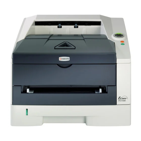
All manuals and user guides at all-guides.com 2H5/2HS-1 1-1-2 Parts names (1) Overall Simplex model Duplex model Figure 1-1-1 1. Top cover 9. MP tray 2. Paper stopper 10. Sub tray 3. Top tray 11. Optional interface slot cover 4. Operation panel 12. - Page 16 All manuals and user guides at all-guides.com 2H5/2HS (2) Operation panel Figure 1-1-2 1. Ready indicator 2. Attention indicator 3. Toner indicator 4. Data indicator 5. Paper indicator 6. Jam indicator 7. Cancel key 8. GO key 1-1-4...
-
Page 17: Machine Cross Section
All manuals and user guides at all-guides.com 2H5/2HS 1-1-3 Machine cross section Simplex model Light path Paper path Paper path (option) Duplex model Light path Paper path Paper path (option) Figure 1-1-3 1. Cassette 5. Developing unit 10. Fuser section 2. - Page 18 All manuals and user guides at all-guides.com 2H5/2HS This page is intentionally left blank. 1-1-6...
-
Page 19: Installation Environment
All manuals and user guides at all-guides.com 2H5/2HS 1-2 Installation 1-2-1 Installation environment ° ° Temperature: 10 to 32.5 C/50 to 90.5 Humidity: 15 to 80%RH Power supply: 120 V AC, 12 A 220 - 240 V AC, 7.2 A (Average) ±... -
Page 20: Unpacking
All manuals and user guides at all-guides.com 2H5/2HS-1 1-2-2 Unpacking 220 - 240 V AC model 120 V AC model Figure 1-2-2 1. Printer 11. Power cord 2. Outer case 12. Pad 3. Bottom pad L 13. Plastic bag 4. Bottom pad R 14. -
Page 21: Removing The Tapes
All manuals and user guides at all-guides.com 2H5/2HS-1 (1) Removing the tapes <Procedure> 1. Remove three tapes. Tape Tape Tape Figure 1-2-3 1-2-3... -
Page 22: Installing The Expanded Memory (Option)
All manuals and user guides at all-guides.com 2H5/2HS-1 1-2-3 Installing the expanded memory (option) <Procedure> 1. Turn off printer power switch. Caution: Do not insert or remove expanded memory while printer power is on. Doing so may cause damage to the printer and the expanded memory. -
Page 23: Installing The Memory Card (Optional)
All manuals and user guides at all-guides.com 2H5/2HS-1 1-2-4 Installing the memory card (optional) <Procedure> 1. Turn off printer power switch. Caution: Do not insert or remove memory card while printer power is on. Doing so may cause damage to the printer and the memory card. -
Page 24: Installing The Network Interface Card (Optional)
All manuals and user guides at all-guides.com 2H5/2HS 1-2-5 Installing the network interface card (optional) <Procedure> 1. Turn off printer power switch. Caution: Do not insert or remove network interface card while printer power is on. Doing so may cause damage to the printer and the network interface card. -
Page 25: Maintenance Mode
All manuals and user guides at all-guides.com 2H5/2HS 1-3 Maintenance Mode 1-3-1 Maintenance mode The product incorporates several service modes which are activated by using the keys on the operation panel or by com- manding from a PC. (1) Executing a service mode Printing a status page for service purpose.........See page 1-3-2. - Page 26 All manuals and user guides at all-guides.com 2H5/2HS Service items Description Printing a status page Description for service purpose Prints a status page for service purpose. The status page includes various printing settings and service cumulative. Purpose To acquire the current printing environmental parameters and cumulative information. Procedure 1.
- Page 27 All manuals and user guides at all-guides.com 2H5/2HS-1 Service items Description Detail of service information Service information [XXXXXXXX][XXXXXXXX][01/00] Total page 9690 /t/U00/F00/N00 /0020/0020/1061/0811/ /0000/0000/ /00/300/81/31/81/31/ A:1234567890123456 /02870284/03028003/83030286/86000086/02000000/02020202/02020202/ /03030303/03030303/03030303/03030303/03000000/03030303/03030303/ SPD1:0203040508090A0B0C0D0F101112131415161718191A1B1C1D1E1F202122235E /00000000/00000000/00000000/00000000/00000000/00000000/00000000/00000000/00000000/00000000/00000000/ /00000000/00000000/00000000/00000000/00000000/00000000/00000000/00000000/00000000/00000000/00000000/ /00000000/00000000/00000000/00000000/00000000/00000000/00000000/00000000/00000000/00000000/00000000/ /00000000/00000000/00000000/00000000/00000000/00000000/00000000/00000000/00000000/00000000/00000000/ /00000000/00000000/00000000/00000000/00000000/00000000/00000000/00000000/00000000/00000000/00000000/ /00000000/00000000/00000000/00000000/00000000/00000000/00000000/00000000/00000000/00000000/00000000/ /00000000/00000000/00000000/00000000/00000000/00000000/00000000/00000000/00000000/00000000/00000000/ /00000000/00000000/00000000/00000000/00000000/00000000/00000000/00000000/00000000/00000000/00000000/ /00000000/00000000/00000000/00000000/00000000/00000000/00000000/00000000/00000000/00000000/00000000/ /00000000/00000000/00000000/00000000/00000000/00000000/00000000/00000000/00000000/00000000/00000000/ /00000000/00000000/00000000/00000000/00000000/00000000/00000000/00000000/00000000/00000000/00000000/ /00000000/00000000/00000000/00000000/00000000/00000000/00000000/00000000/00000000/00000000/00000000/ /00000000/00000000/00000000/00000000/00000000/00000000/00000000/00000000/00000000/00000000/00000000/ /00000000/00000000/00000000/00000000/00000000/00000000/00000000/00000000/00000000/00000000/00000000/...
- Page 28 1 = 0: Overseas, 1: Domestic (Japan) [First byte/Second byte bit 2, 3 (Not used) (displayed in OEM model bit 4 = 0: Kyocera, 1: OEM only)] bit 5 = 0: For Europe, 1: For US bit 6 = 0: Non MICR mode, 1: MICR mode...
- Page 29 All manuals and user guides at all-guides.com 2H5/2HS-1 Service items Description Items Description Fixed asset number (Maximum 16 characters) Paper type attributes Paper type setting value from 1 to 28 (fuser, weight, duplex) (unused paper type are always 0x00.) Paper type attributes Paper type setting value from 1 to 28 (density) (unused paper type are always 0x00.) Memory SPD information (slot...
- Page 30 All manuals and user guides at all-guides.com 2H5/2HS Service items Description Printing an event log Description (EVENT LOG) Prints a history list of occurrences of paper jam, self-diagnostics, toner replacements, etc. Purpose To allow machine malfunction analysis based on the frequency of paper misfeeds, self diag- nostic errors and replacements.
- Page 31 All manuals and user guides at all-guides.com 2H5/2HS Service items Description EVENT LOG [EB20MA001/2HS_1000.001.019][40.00SFLB][01] Firmware version: 2HS_30000.001.024 Released: 13/July/2007 Printed page(s) 12345 Paper Jam Log Service Call Log Count. Event Count. Service Code 9993 10.48.01.80.01.01 11234 01.6000 10000 01.6000 9992 10.48.01.80.01.01 9999 01.6000...
- Page 32 [First byte/Second byte (dis- bit 2, 3 (Not used) played in OEM mode only)] bit 4 = 0: Kyocera, 1: OEM bit 5 = 0: For Europe, 1: For US bit 6 = 0: Non MICR mode, 1: MICR mode...
- Page 33 All manuals and user guides at all-guides.com 2H5/2HS Service items Description Items Description (a) Cause of paper jam cont. 10: Paper does not arrive at the registration sensor. (MP tray) [42] 10: Paper does not arrive at the registration sensor. (Cassette 1) [31] 10: Paper does not arrive at the registration sensor.
- Page 34 All manuals and user guides at all-guides.com 2H5/2HS Service items Description Items Description Duplex model cont. Printer (MP tray) (Fuser/paper exit section) [50] [42] Printer inside [47] [48] (Duplex/conveying [49] section) [31] (Cassette 1) [32] Paper feeder 1 (Cassette 2) Registration sensor Paper sensor [33]...
- Page 35 All manuals and user guides at all-guides.com 2H5/2HS Service items Description Items Description Service Call (Self Count. Service Code diagnostic error) Remembers 1 to 8 of occur- The total page count at Self diagnostic error code rence of self diagnostics error. the time of the self diag- (See page 1-4-4) nostics error.
- Page 36 All manuals and user guides at all-guides.com 2H5/2HS Service items Description Toner install mode Description Replenishes toner rapidly from the toner container into the developing unit. Purpose To execute after replacing the developing unit to replenish toner rapidly into the developing unit.
-
Page 37: Paper Misfeed Detection
All manuals and user guides at all-guides.com 2H5/2HS 1-4 Troubleshooting 1-4-1 Paper misfeed detection (1) Paper misfeed indication If paper jams in the paper conveying system, or no paper sheets are fed at all, the printer automatically goes offline, and the jam indicator will flash rapidly. -
Page 38: Paper Misfeed Detection Condition
All manuals and user guides at all-guides.com 2H5/2HS (2) Paper misfeed detection condition Simplex model Registration sensor Paper sensor Paper exit sensor PF paper feed sensor PF paper sensor Printer Paper feeder 1 (Option) Duplex model Registration sensor Paper sensor MP paper sensor Paper exit sensor PF paper feed sensor... -
Page 39: Self-Diagnostic Function
All manuals and user guides at all-guides.com 2H5/2HS 1-4-2 Self-diagnostic function (1) Self-diagnostic function The printer is equipped with self-diagnostic function which automatically halts the printer when an error is detected. The four indicators (Jam, Paper, Attention, Toner) are simultaneously lit, then indicate a specific error by the combination of the four indicators. -
Page 40: Self Diagnostic Codes Indication
All manuals and user guides at all-guides.com 2H5/2HS-1 (2) Self diagnostic codes indication Sequence of display Indicates the occurrence of a self diagnostics error. 1.6 s 1.6 s 0.8 s 0.8 s Example of self-diagnostic code: 2610 (Refer to the following code conversion table) 0.8 s 0.8 s 0.8 s... -
Page 41: Self Diagnostic Codes
All manuals and user guides at all-guides.com 2H5/2HS (3) Self diagnostic codes Remarks Code Contents Causes Check procedures/corrective measures 0150 Control PWB EEPROM error Improper installa- Check the installation of the EEPROM Detecting control PWB EEPROM (U300) tion control PWB (U300) and remedy if necessary (See page communication error. - Page 42 All manuals and user guides at all-guides.com 2H5/2HS Remarks Code Contents Causes Check procedures/corrective measures 2610 PF paper feed motor error (Paper Defective harness Reinsert the connector. Also check for conti- feeder 1) between PF paper nuity within the connector harness. If none, The PF paper feed motor of paper feeder feed motor and PF remedy or replace the harness (Refer to the...
- Page 43 All manuals and user guides at all-guides.com 2H5/2HS Remarks Code Contents Causes Check procedures/corrective measures 6000 Broken fuser heater lamp wire Poor contact in the Reinsert the connector (See page 1-5-16). The fuser temperature does not rise after fuser thermistor the fuser heater lamp has been turned connector termi- nals.
- Page 44 All manuals and user guides at all-guides.com 2H5/2HS Remarks Code Contents Causes Check procedures/corrective measures 6400 Zero cross signal error Defective harness Reinsert the connector. Also check for conti- The zero cross signal does not reach the between high volt- nuity within the connector harness.
-
Page 45: Image Formation Problems
All manuals and user guides at all-guides.com 2H5/2HS 1-4-3 Image formation problems (1)Completely blank (2)All-black printout. (3)Dropouts. (4)Black dots. (5)Black horizontal printout. streaks. See page 1-4-10 See page 1-4-10 See page 1-4-11 See page 1-4-11 See page 1-4-11 (6)Black vertical (7)Unsharpness. -
Page 46: Completely Blank Printout
All manuals and user guides at all-guides.com 2H5/2HS (1) Completely blank printout. Print example Causes Check procedures/corrective measures Defective drum unit or developing Open the top cover and check that the drum unit and develop- unit. ing unit are correctly seated. Investigate that the terminals between the main charger unit and the drum unit are not in loose contact (See page 1-5-12 and 1-5-11). -
Page 47: Dropouts
All manuals and user guides at all-guides.com 2H5/2HS (3) Dropouts. Print example Causes Check procedures/corrective measures Defective developing roller (develop- If the defects occur at regular intervals of 62.8 mm/2 " (See ing unit). page 2-4-3), the problem may be the damaged developing roller (in the developing unit). -
Page 48: Black Vertical Streaks
All manuals and user guides at all-guides.com 2H5/2HS (6) Black vertical streaks. Print example Causes Check procedures/corrective measures Adhesion of oxide to main charger Remove the drum unit (See page 1-5-12). Slide the charger wire. cleaner (green) left and right 2 or 3 times to clean the charger wire, then return it to its original position (CLEANER HOME POSITION). -
Page 49: Dirt On The Top Edge Or Back Of The Paper
All manuals and user guides at all-guides.com 2H5/2HS (9) Dirt on the top edge or back of the paper. Print example Causes Check procedures/corrective measures Toner contamination in various parts. Dirty edges and back of the paper can be caused by toner accumulated on such parts as the paper chute guide, paper conveying paths, the bottom of the drum and developing unit, and the fuser unit inlet. -
Page 50: Electric Problems
All manuals and user guides at all-guides.com 2H5/2HS 1-4-4 Electric problems Problem Causes Check procedures/corrective measures (1)The machine does No electricity at the power Measure the input voltage. not operate when the outlet. power switch is The power cord is not Check the contact between the power plug and the outlet. - Page 51 All manuals and user guides at all-guides.com 2H5/2HS Problem Causes Check procedures/corrective measures (6)developing clutch Broken developing clutch Check for continuity across the coil. If none, replace the develop- does not operate. coil. ing clutch. Defective harness between Reinsert the connector. Also check for continuity within the con- developing clutch and con- nector harness.
-
Page 52: Mechanical Problems
All manuals and user guides at all-guides.com 2H5/2HS 1-4-5 Mechanical problems Problem Causes/check procedures Corrective measures (1)No primary paper Check if the surfaces of the paper feed roller Clean with isopropyl alcohol. feed. is dirty with paper powder. Check if the paper feed roller is deformed. Check visually and replace any deformed paper feed roller (assembly) (See page 1-5- Defective paper feed clutch installation. -
Page 53: Assembly And Disassembly
All manuals and user guides at all-guides.com 2H5/2HS-1 1-5 Assembly and Disassembly 1-5-1 Precautions for assembly and disassembly (1) Precautions Be sure to turn the power switch off and disconnect the power plug before starting disassembly. When handling PWBs, do not touch connectors with bare hands or damage the PWB. Do not touch any PWB containing ICs with bare hands or any object prone to static charge. -
Page 54: How To Tell A Genuine Kyocera Mita Toner Container
A black-colored band when seen through the left side window A shiny or gold-colored band when seen through the right side window The above will reveal that the toner container is a genuine Kyocera Mita branded toner container, otherwise, it is a coun- terfeit. -
Page 55: Outer Covers
All manuals and user guides at all-guides.com 2H5/2HS 1-5-2 Outer covers (1) Detaching and refitting the top cover Procedure 1. Open the top cover. 2. Remove two screws. Top cover Screw Screw Figure 1-5-3 3. Extract the boss from the hole. 4. -
Page 56: Detaching And Refitting The Right And Left Covers
All manuals and user guides at all-guides.com 2H5/2HS (2) Detaching and refitting the right and left covers Procedure 1. Remove the top cover (See page 1-5-3). 2. Remove the cassette (See page 1-5-6). 3. Open the front cover. 4. Unhook seven hooks and then remove the right cover. - Page 57 All manuals and user guides at all-guides.com 2H5/2HS 5. Unhook seven hooks and then remove the left cover. Left cover Hooks Figure 1-5-6 1-5-5...
-
Page 58: Paper Feed Section
All manuals and user guides at all-guides.com 2H5/2HS 1-5-3 Paper feed section (1) Detaching and refitting the paper feed assembly (paper feed roller and pickup roller) Procedure 1. Remove the cassette. Cassette Figure 1-5-7 2. Slide the feed shaft. 3. While pressing the lever and then remove the paper feed roller assembly. - Page 59 All manuals and user guides at all-guides.com 2H5/2HS 4. Check or replace the paper feed assembly Paper feed roller and refit all the removed parts. Feed shaft assembly When refitting the paper feed roller assem- bly, be sure to align the paper feed roller pivot with the slotted hole on the feed shaft.
-
Page 60: Detaching And Refitting The Retard Roller Assembly
All manuals and user guides at all-guides.com 2H5/2HS (2) Detaching and refitting the retard roller assembly Procedure 1. Remove the cassette (See page 1-5-6). Retard guide 2. Push the bottom plate down until it locks. Hook 3. Unhook two hooks and then remove the retard guide. - Page 61 All manuals and user guides at all-guides.com 2H5/2HS 5. Check or replace the retard roller assembly and refit all the removed parts. Retard roller Caution: Before refitting the retard roller assembly assembly, firmly install the spring onto the projection of the retard roller assembly. Projection Spring Figure 1-5-12...
-
Page 62: Detaching And Refitting The Mp Paper Feed Roller (Duplex Model Only)
All manuals and user guides at all-guides.com 2H5/2HS (3) Detaching and refitting the MP paper feed roller (Duplex model only) Procedure 1. Open the front cover. 2. Pull the MP feed holder (lever) down ( ). 3. Slide the MP feed holder ( ). 4. -
Page 63: Developing Section
All manuals and user guides at all-guides.com 2H5/2HS 1-5-4 Developing section (1) Detaching and refitting the developing unit Procedure 1. Open the top cover. Top cover 2. Open the front cover. 3. Remove the developing unit (with toner con- tainer). 4. -
Page 64: Drum Section
All manuals and user guides at all-guides.com 2H5/2HS 1-5-5 Drum section (1) Detaching and refitting the drum unit Procedure 1. Remove the developing unit (See page 1-5- 11). 2. Remove the drum unit. 3. Check or replace the drum unit and refit all the removed parts. -
Page 65: Detaching And Refitting The Main Charger Unit
All manuals and user guides at all-guides.com 2H5/2HS-1 (2) Detaching and refitting the main charger unit Procedure 1. Remove the drum unit (See page 1-5-12). 2. Remove the tape. 3. While pushing on the main plate ( ), slide the main charger unit ( ). Tape Main charger unit Drum unit... -
Page 66: Transfer/Separation Section
All manuals and user guides at all-guides.com 2H5/2HS 1-5-6 Transfer/separation section (1) Detaching and refitting the transfer roller Procedure 1. Remove the developing unit (See page 1-5- 11). 2. Remove the drum unit (See page 1-5-12). 3. Slide the paper chute guide and unhook the hooks. - Page 67 All manuals and user guides at all-guides.com 2H5/2HS 5. Remove the transfer roller’s shaft from the Shaft both transfer bushes. 6. Remove the gear Z16 from the transfer roller. Transfer roller Shaft Transfer roller Transfer roller Transfer roller Gear Z16 Figure 1-5-20 7.
-
Page 68: Fuser Section
All manuals and user guides at all-guides.com 2H5/2HS 1-5-7 Fuser section (1) Detaching and refitting the fuser unit Procedure 1. Remove the outer covers (See page 1-5-3). 2. Remove two connectors. 3. Release the wires form wire clamps. Wires Wire clamps Connector (Fuser heater lamp) Connector... - Page 69 All manuals and user guides at all-guides.com 2H5/2HS 5. Remove the rear cover. Rear cover Figure 1-5-24 6. Remove two screws and then remove the fuser unit. 7. Check or replace the fuser unit and refit all the removed parts. Fuser unit Screw Screw...
-
Page 70: Switching The Fuser Pressure
All manuals and user guides at all-guides.com 2H5/2HS (2) Switching the fuser pressure The fuser pressure may be decreased to suppress the print quality problems such as paper creases and curls. It must be cautioned that decreasing the fuser pressure could cause loose toner fusing. Procedure 1. -
Page 71: Pwbs
All manuals and user guides at all-guides.com 2H5/2HS 1-5-8 PWBs (1) Detaching and refitting the control PWB Procedure 1. Remove the right cover (See page 1-5-4). 2. Remove the connectors form the control PWB. Simplex model: Twelve Control PWB Duplex model: Thirteen 3. - Page 72 All manuals and user guides at all-guides.com 2H5/2HS 4. Remove five screws. Connectors A: Duplex model only 5. Remove the connectors form the control Simplex model: Two PWB. Duplex model: Three Simplex model: Two Duplex model: Three 6. Unhook the hook and then remove the con- trol PWB assembly.
- Page 73 All manuals and user guides at all-guides.com 2H5/2HS 7. Remove five screws and then remove the control PWB. Screw 8. Check or replace the control PWB and refit all the removed parts. Screw To replace the control PWB, remove the Screw EEPROM (U300) from the old control PWB and mount it to the new control PWB.
-
Page 74: Detaching And Refitting The Power Source Pwb
All manuals and user guides at all-guides.com 2H5/2HS (2) Detaching and refitting the power source PWB Procedure 1. Remove the top cover (See page 1-5-3). 2. Remove the left cover (See page 1-5-4). 3. Remove four connectors. Connector Connector Connector Connector (YC104) Figure 1-5-30... - Page 75 All manuals and user guides at all-guides.com 2H5/2HS 6. Remove four screws and then remove the Screws power source plate from the power source PWB. 7. Check or replace the power source PWB and refit all the removed parts. Caution: The power source film must be installed in the specified position.
-
Page 76: Detaching And Refitting The Operation Panel Pwb
All manuals and user guides at all-guides.com 2H5/2HS (3) Detaching and refitting the operation panel PWB Procedure 1. Remove the top cover (See page 1-5-3). Screw 2. Remove two screws and then remove the panel cover. 3. Remove the operation panel PWB. 4. -
Page 77: Detaching And Refitting The High Voltage Pwb
All manuals and user guides at all-guides.com 2H5/2HS (4) Detaching and refitting the high voltage PWB Procedure 1. Remove the developing unit (See page 1-5- 11). 2. Remove the drum unit (See page 1-5-12). 3. Remove the cassette (See page 1-5-6). Stop ring 4. - Page 78 All manuals and user guides at all-guides.com 2H5/2HS 12. Remove four screws. 13. Unhook three hooks and then remove the lower base cover. Lower base cover Hook Hook Hook Screws Screws Lower base cover Figure 1-5-36 1-5-26...
- Page 79 All manuals and user guides at all-guides.com 2H5/2HS 14. Remove the spring. 15. Remove the cassette pin. Cassette pin Spring Figure 1-5-37 16. Remove two connectors and then remove the high voltage PWB. 17. Remove the cassette pin holder from the high voltage PWB.
- Page 80 All manuals and user guides at all-guides.com 2H5/2HS 18. Check or replace the high voltage PWB and refit all the removed parts. When refitting the high voltage PWB, be High voltage PWB careful about following points. - Position the ground plate so that it is atop the high voltage PWB.
-
Page 81: Others
All manuals and user guides at all-guides.com 2H5/2HS 1-5-9 Others (1) Detaching and refitting the main motor Procedure 1. Remove the right cover (See page 1-5-4). 2. Remove the connector. Connector Figure 1-5-40 3. Remove the M3 screw and two M4 screws. 4. -
Page 82: Detaching And Refitting The Laser Scanner Unit
All manuals and user guides at all-guides.com 2H5/2HS (2) Detaching and refitting the laser scanner unit Procedure 1. Remove the right cover (See page 1-5-4). 2. Remove the connector from the control PWB. 3. Release the wire clamp. 4. Draw in the connector inside. Connector Control PWB Clamp... - Page 83 All manuals and user guides at all-guides.com 2H5/2HS 5. Remove four screws and then remove the laser scanner unit. 6. Check or replace the laser scanner unit and refit all the removed parts. Screws Screws Laser scanner unit Figure 1-5-43 1-5-31...
-
Page 84: Detaching And Refitting The Eraser Lamp
All manuals and user guides at all-guides.com 2H5/2HS (3) Detaching and refitting the eraser lamp Procedure 1. Remove the laser scanner unit (See page 1- 5-30). 2. Remove the connector. 3. Remove the eraser lamp. 4. Check or replace the eraser lamp and refit all the removed parts. -
Page 85: Direction Of Installing The Left And Right Cooling Fan Motors
All manuals and user guides at all-guides.com 2H5/2HS (4) Direction of installing the left and right cooling fan motors When detaching or refitting the left and/or right cooling fan motors, be careful of the airflow direction (intake or exhaust). Right cooling Left cooling fan motor fan motor... - Page 86 All manuals and user guides at all-guides.com 2H5/2HS This page is intentionally left blank. 1-5-34...
-
Page 87: Firmware
All manuals and user guides at all-guides.com 2H5/2HS 1-6 Firmware 1-6-1 Downloading firmware Firmware files are named after the following codes: Firmware file name example Compression Software ID S2HS_1000001021.cmp Product code Pause (period) 2H5: Simplex model 2HS: Duplex model Build number Pause (underscore) Update history Classification (Normally: 0) -
Page 88: Downloading The Firmware From The Memory Card
All manuals and user guides at all-guides.com 2H5/2HS (1) Downloading the firmware from the memory card To download data written in a memory card (CompactFlash) to the printer, proceed as explained in this section. CAUTION Downloading firmware takes several minutes. Do not turn power off during downloading. If downloading is interrupted by an accidental power failure, etc., the control PWB may have to be replaced. - Page 89 All manuals and user guides at all-guides.com 2H5/2HS 5. Turn printer power on. The printer starts and finishes downloading automatically. Sequence of display Indication example Off (Amber) Downloading start Lit (Green) Lit (Amber) 4.8 s Off (Amber) Supervisor Off (Green) mode Lit (Amber) 4.8 s...
- Page 90 All manuals and user guides at all-guides.com 2H5/2HS 6. Confirm that downloading was finished nor- mally (See previous page). 7. Turn power off. 8. Remove the memory card. 9. Secure the optional interface slot cover by using two screws. Memory card slot 10.
-
Page 91: Paper Feed/Conveying Section
All manuals and user guides at all-guides.com 2H5/2HS 2-1 Mechanical Construction 2-1-1 Paper feed/conveying section Paper feed/conveying section consists of the paper feed unit that feeds paper from the cassette and the MP tray paper feed unit that feeds paper from the MP tray, and the paper conveying section that conveys the fed paper to the transfer/ separation section. -
Page 92: Mp Tray Paper Feed Section
All manuals and user guides at all-guides.com 2H5/2HS (2) MP tray paper feed section Simplex model Figure 2-1-3 MP tray paper feed section MP upper cover MP lower cover MP base MP guide R/L MPF frame MPF turn guide Control PWB MMOTRDYN YC305-3 MOTCLK... - Page 93 All manuals and user guides at all-guides.com 2H5/2HS Duplex model Figure 2-1-5 MP tray paper feed section MP paper feed roller MPF frame MPF separation pad MPF guide R/L MPF separator (10) MPF base MPF bottom plate (11) MPF middle tray MPF friction pad (12) MPF upper tray MP paper sensor...
-
Page 94: Paper Conveying Section
All manuals and user guides at all-guides.com 2H5/2HS (3) Paper conveying section Figure 2-1-7 Paper conveying section Lower registration roller Upper registration roller Registration sensor Actuator (registration sensor) Feed pulley Control PWB MMOTRDYN YC305-3 MOTCLK YC305-4 Main motor REMOTEN YC305-5 REGDRN Registration YC308-2... -
Page 95: Drum Section
All manuals and user guides at all-guides.com 2H5/2HS 2-1-2 Drum section (1) Drum section The durable layer of organic photoconductor (OPC) is coated over the aluminum cylinder base. The OPC tend to reduce its own electrical conductance when exposed to light. After a cyclic process of charging, exposure, and development, the electrostatic image is constituted over the OPC layer. -
Page 96: Main Charger Unit
All manuals and user guides at all-guides.com 2H5/2HS (2) Main charger unit As the drum rotates in a “clean (neutral)” state, its photoconductive layer is given a uniform, positive (+) corona charge dis- persed by the main charger wire. Due to high-voltage scorotron charging, the charging wire can get contaminated by oxi- dization after a long run. -
Page 97: Expose Section
All manuals and user guides at all-guides.com 2H5/2HS 2-1-3 Expose section (1) Laser scanner unit The charged surface of the drum is then scanned by the laser beam from the laser scanner unit. The laser beam (780 nm wavelength) beam is dispersed as the polygon motor revolves to reflect the laser beam over the drum. - Page 98 All manuals and user guides at all-guides.com 2H5/2HS Figure 2-1-13 Laser scanner unit Polygon motor (mirror) Laser diode (APC PWB) Collimator lens Cylindrical lens F-θ lens F-θ lens PD mirror SOS lens Pin photo diode sensor (PD PWB) (10) LSU mirror 2-1-8...
-
Page 99: Developing Section
All manuals and user guides at all-guides.com 2H5/2HS 2-1-4 Developing section The latent image constituted on the drum is developed into a visible image. The developing roller contains a 3-pole (S-NS) magnet roller and an aluminum cylinder rotating around the magnet roller. Toner attracts to the magnet sleeve since it is powdery ink made of black resin bound to iron particles. -
Page 100: Transfer/Separation Section
All manuals and user guides at all-guides.com 2H5/2HS 2-1-5 Transfer/separation section The transfer/separation section consists of the transfer roller, discharger brush and paper chute guide. A high voltage gen- erated by the high voltage PWB is applied to the transfer roller for transfer charging. Paper after transfer is separated from the drum. -
Page 101: Cleaning Section
All manuals and user guides at all-guides.com 2H5/2HS 2-1-6 Cleaning section After the transferring process, the drum needs to be physically cleaned of toner which is residual after the development process. The cleaning blade is constantly pressed against the drum and scrapes the residual toner off to the sweep roller. The waste toner is collected at the output end of the sweep roller and sent back to the toner container, into the waste toner reservoir. -
Page 102: Fuser Section
All manuals and user guides at all-guides.com 2H5/2HS 2-1-7 Fuser section The toner on the paper is molten and pressed into the paper as it passes between the heat roller and the press roller in the fuser unit. The heat roller has a heater lamp inside which continuously turns on and off by the fuser thermistor to maintain the constant temperature onto the heat roller surface. - Page 103 All manuals and user guides at all-guides.com 2H5/2HS Fuser unit High Power Control PWB voltage source PWB Fuser thermal cutout HEATN YC103-6 YC311-5 YC102-1 SLEEP YC103-7 YC311-6 ZCROSS YC102-3 YC103-8 YC311-3 Fuser heater lamp Fuser thermistor THERM YC311-16 Figure 2-1-21 Fuser section block diagram 2-1-13...
-
Page 104: Paper Exit Section
All manuals and user guides at all-guides.com 2H5/2HS 2-1-8 Paper exit section The paper exit section transports the paper which passed the fuser unit towards the top tray. The paper which passed through the fuser unit turns on the actuator (exit sensor) in the fuser unit, and is led by the guide comprised of the rear cover, frame and the FD cover guide, finally reaching the upper FD roller. - Page 105 All manuals and user guides at all-guides.com 2H5/2HS Fuser unit Control PWB EXITN YC307-3 Exit sensor Figure 2-1-23 Paper exit section block diagram 2-1-15...
-
Page 106: Duplex/Conveying Section (Duplex Model Only)
All manuals and user guides at all-guides.com 2H5/2HS 2-1-9 Duplex/conveying section (duplex model only) The duplex/conveying section consists of conveying path which sends the paper sent from the exit section to the paper feed/conveying section when duplex printing. Figure 2-1-24 Duplex/conveying section DU cover B DU holder Middle pulley B... -
Page 107: Electrical Parts Layout
All manuals and user guides at all-guides.com 2H5/2HS 2-2 Electrical Parts Layout 2-2-1 Electrical parts layout (1) PWBs Simplex model Machine left Machine inside Machine right Duplex model Machine left Machine inside Machine right Figure 2-2-1 PWBs 1. Control PWB ..........Main controller: Controls the software such as the print data processing and provides the interface with computers. - Page 108 All manuals and user guides at all-guides.com 2H5/2HS 6. PD PWB............Controls horizontal synchronizing timing of laser beam. 7. Zener PWB ..........Adjusts the drum surface potential. 8. Eraser lamp PWB ........Eliminates the residual electrostatic charge on the drum. 2-2-2...
-
Page 109: Switches And Sensors
All manuals and user guides at all-guides.com 2H5/2HS (2) Switches and sensors Simplex model Machine left Machine inside Machine right Duplex model Machine left Machine inside Machine right Figure 2-2-2 Switches and sensors 1. Power switch..........Turns ON/OFF the AC power source. 2. -
Page 110: Other Electrical Components
All manuals and user guides at all-guides.com 2H5/2HS (3) Other electrical components Simplex model Machine left Machine inside Machine right Duplex model Machine left Machine inside Machine right Figure 2-2-3 Other electrical components 1. Main motor ............Drives the paper feed/conveying section and fuser unit. 2. -
Page 111: Power Source Pwb
All manuals and user guides at all-guides.com 2H5/2HS 2-3 Operation of the PWBs 2-3-1 Power source PWB Power source PWB Left +24V1 cooling fan motor ZCROSS Zero cross signal circuit Power switch SLEEP AC input Switching +5V1 regulator circuit +24V2 Fuser heater Interlock lamp control... - Page 112 All manuals and user guides at all-guides.com 2H5/2HS YC104 YC105 YC102 YC103 YC101 Figure 2-3-2 Power source PWB silk-screen diagram Connector Signal Voltage Description YC101 LIVE 120 V AC AC power input Connected 220 - 240 V AC to the AC NEUTRAL 120 V AC AC power input...
-
Page 113: Control Pwb
All manuals and user guides at all-guides.com 2H5/2HS-1 2-3-2 Control PWB Control PWB Engine Main controller Laser scanner unit I/F Duplex solenoid (duplex model only) Registration clutch Operation MP paper feed solenoid panel PWB I/F (duplex model only) Paper feed clutch USB I/F +3.3 V Developing clutch... - Page 114 All manuals and user guides at all-guides.com 2H5/2HS YC316 YC317 YC307 U300 Figure 2-3-4 Control PWB silk-screen diagram 2-3-4...
- Page 115 All manuals and user guides at all-guides.com 2H5/2HS Connector Signal Voltage Description LED1 3.3/0 V DC Paper indicator display: On/Off Connected LED2 3.3/0 V DC Jam indicator display: On/Off to the opera- Analog Cancel key/GO key: On/Off tion panel SGND Ground LED3 3.3/0 V DC...
- Page 116 All manuals and user guides at all-guides.com 2H5/2HS Connector Signal Voltage Description YC311 TCNT Transfer current control signal Connected MCNT Main charger output control signal to the high THVDR 0/3.3 V DC Transfer bias output signal: On/Off voltage CASE Analog Cassette switch: On/Off THERM Analog...
-
Page 117: Appendixes
All manuals and user guides at all-guides.com 2H5/2HS 2-4 Appendixes 2-4-1 Appendixes (1) Wiring diagram Simplex model 2-4-1... - Page 118 All manuals and user guides at all-guides.com 2H5/2HS Duplex model 2-4-2...
-
Page 119: Repetitive Defects Gauge
All manuals and user guides at all-guides.com 2H5/2HS (2) Repetitive defects gauge First occurrence of defect [24.99 mm/1"] Upper registration roller [37.68 mm/1 "] Lower registration roller [45.216 mm/1 "] Transfer roller [62.8 mm/2 "] Developing roller (developing unit) [73.162 mm/2 "] Heat roller (fuser unit) [78.5 mm/3 "] Press roller (fuser unit) -
Page 120: Self Diagnostic Codes Indication (Animation)
All manuals and user guides at all-guides.com 2H5/2HS-1 (3) Self diagnostic codes indication (Animation) Click the icon to play the animation of the indicator combinations. Right-click an indicator, then select Playback and Play to play the animation repeatedly. To play the animation, you have to install Adobe Flash Player and Adobe Reader (Version 6.01 or more) to your PC. If the animation is not displayed, you should get the latest version from Adobe site (http://www.adobe.com/downloads/). - Page 121 All manuals and user guides at all-guides.com 2H5/2HS-1 Indication Contents Broken fuser thermistor wire Zero cross signal error Control PWB checksum error Control PWB RAM checksum error Control PWB general failure Control PWB engine communication error Control PWB engine checksum error Control PWB video data control error 2-4-5...
- Page 122 All manuals and user guides at all-guides.com 2H5/2HS This page is intentionally left blank. 2-4-6...
- Page 123 All manuals and user guides at all-guides.com...
- Page 124 All manuals and user guides at all-guides.com...
Need help?
Do you have a question about the FS-1100 and is the answer not in the manual?
Questions and answers