MIR 100 User Manual
Hide thumbs
Also See for 100:
- User manual (57 pages) ,
- Quick start manual (38 pages) ,
- Quick start manual (42 pages)

Subscribe to Our Youtube Channel
Related Manuals for MIR 100


Summary of Contents for MIR 100
- Page 1 MiR 100 Mobile Industrial Robots User Guide Document version 1.4 Original version (en)
- Page 2 In addition, the content of the document is subject to change without prior notice. Every precaution has been taken in the preparation of this manual. Nevertheless, MiR assumes no responsibility for errors or omissions or any damages resulting from the use of the information contained.
-
Page 3: Table Of Contents
Table of contents Introduction ............................5 Document history ........................5 Product presentation ........................5 The delivery ..........................6 Identification label ........................6 Safety ..............................7 Safety concept ..........................7 General safety instructions ......................7 Lithium battery ........................... 9 Safety circuit ..........................10 Applied standards ........................ - Page 4 Appendix A: Payload specifications ......................26 Appendix B: MiR100 dimension drawings ....................28 Appendix C: Declaration of conformity ....................29 Appendix D: Accessories made standard as of release 1.5 ..............30 Application interface ..........................30 Interface to docking station ......................... 30...
-
Page 5: Introduction
Introduction 1 Introduction This user guide contains information about the vehicle structure, use and maintenance. Latest version and further documentation of special applications are available at the support site https://mirrobot.atlassian.net/servicedesk/customer/portal/1. The user guide is intended for retailers and end-customers responsible for or directly involved in the integration, operation and field maintenance of the MiR100. -
Page 6: The Delivery
• Tablet Kit (optional) 1.4 Identification label The identification label of the MiR is placed inside the robot next to the rear scanner and shows the following information: Mobile Industrial Robots ApS declares that the MiR100 meets the requirements of the applicable EC directives (see chapter 2 Safety) Serial no. -
Page 7: Safety
Safety 2 Safety 2.1 Safety concept This manual contains notices you have to observe in order to ensure your personal safety, as well as to prevent damage to property. The notices referring to your personal safety are highlighted in the manual by a safety alert symbol. - Page 8 4. Do not overload the vehicle Risk of personal injury and/or damage to the vehicle The maximum payload is 100 kg (220.5 lb.) for load on top of the vehicle. If exceeded it may cause overturning, falling load and damage to the vehicle.
-
Page 9: Lithium Battery
7. Do not remove components for separate use Manufacturer’s warranty will be void MiR takes not responsibility for damage to components removed from the vehicle and used for other purposes than the intended. 8. Avoid blocking of sensors... -
Page 10: Safety Circuit
Safety 2.4 Safety circuit If a person or other moving object enters the safety zones for MiR100 where the planner due to response time, errors etc. does not respond, the safety circuit will force the robot into emergency stop and the robot stops immediately. -
Page 11: Description
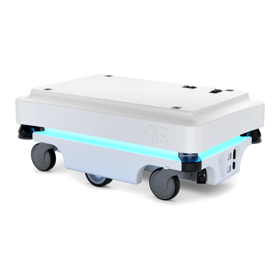
Description 3 Description 3.1 Vehicle main parts Top cover Ultrasonic sensors 14 Front skirt Laser scanner On/Off button and scanner 15 Drive wheel Rear edge cover reset button (yellow) Caster wheel 10 Protective cover 16 Side skirt Protection cover 11 HDMI port 17 Caster wheel Power port 12 USB port... -
Page 12: Main Components
Router Local network. On/Off Button Controls Start/Stop battery power. 24/24 V switch Provides safety Power to the MiR board. 5V Power Supply mode power supply components. Ensures stable voltage. Fuse group Plug connections to chassis Main power for the robot. -
Page 13: Sensor Systems
Description 3.3 Sensor systems External sensors Internal sensors • Camera • Gyro • Laser scanner • Motor encoder • Ultrasonic sensors 3.4 Light indicators The light signals on the MiR100 indicate the current operational state. Colors may be adapted to individual user needs but MiR100 is delivered with the following setup. -
Page 14: The Vehicle's Main Functions
Description 3.6 The vehicle’s main functions 1. Driving in a populated workspace The vehicle is designed to operate among people 2. Overall route planning and local adjustments The vehicle plans a general route to its target destinations. When the vehicle encounters obstacles which are not in the map (like people and objects), adjustments are made to the route. -
Page 15: Technical Specifications
10 hours or 20 km (12.5 mi) Maximum speed: 1.5 m/s (5 ft./s) corresponding to 5.6 km/hour (3.5 mi/h) Maximum grade increase: 5% with 100 kg (220.5 lb.) load Ambient temperature range: +5° C to +50° C (+41° F to + 122° F) Humidity: 10-95% non-condensing... - Page 16 Technical specifications Charging time: Up to 3 hours (0-80% 2 hours) SICK laser scanners (2pcs) Range: 270° visual protection Visual indicators LED color light bar (on four sides): Indication of operating status Audio indicators Built-in loudspeaker: 3 W (below 60 dB) Top module Maximum height from floor to top: 1800 mm (70.75”)
-
Page 17: Getting Started
Getting started 5 Getting started 5.1 Unpacking 1 Lift off the lid from the pallet and remove the top foam and side foam pieces; then remove the two pallet frames. 2 Lift off the top cover of the vehicle. • Remove the emergency stop box placed inside the robot, (1). -
Page 18: Charging The Vehicle
Getting started 4 Place the packaging top lid as a ramp as shown. Using the manual joystick mode, you can now drive the vehicle down the ramp. Note: It is recommended to drive it down backwards. 5.2 Charging the vehicle To charge the vehicle: Turn the vehicle off on the black On/Off button. -
Page 19: Placing The Top Module
Getting started 5.3 Placing the top module Top modules and payload should be fastened using the self-tightening conically shaped mooring holes: Caution: Before adding the top module, the emergency stop box must be removed and remounted on the top module in a position where it can be reached from all sides of the module. Notice: Stay within the specifications for weight and the payload’s center of gravity, see Appendix A. -
Page 20: Test The Vehicle
Getting started 5.5 Test the vehicle Before the first drive, test the vehicle: Log on to the MiR Web Interface for the vehicle – see attached setup sheet. Go to Service > Status > Diagnostics. Make sure that all components work: click on individual components or click on Expand all. -
Page 21: Shutting Down The Vehicle
Getting started 5.6 Shutting down the vehicle To turn off the vehicle: Use the emergency stop – press the red Emergency stop button. That will turn off the power to the motors. Turn the black On/Off button on the front of the vehicle. - Page 22 Getting started 1 Place the packaging top lid as a ramp on the pallet. Using the manual joystick mode, you can now drive the vehicle onto the pallet. Note: It is recommended to back the vehicle onto the pallet. Turn the vehicle off, dismount the emergency stop, and remove the top cover.
- Page 23 Getting started 5 Place the dismounted emergency stop on top of the battery 6 Put the top cover back on and place the pallet frames 7 Fit the end foam in the rear and the side foam in each corner. Tip: the side foam is easily added by first placing the foam diagonally by the two laser scanners.
- Page 24 Getting started 9 Place the lid and tie down the box making sure the lid does not come undone. User Guide v. 1.4...
-
Page 25: Maintenance
If the vehicle experiences an emergency stop, pull it to an unobstructed area. • If MiR shows an error message on the way to destination, check if the destination is blocked or if the vehicle does not drive well: 1. Make sure that the vehicle’s destination corresponds with its position on the map. -
Page 26: Appendix A: Payload Specifications
Appendix A Appendix A: Payload specifications The following drawings illustrate the center of mass (CoM) specifications for safe operation at different payloads. Maximum load height should be 1.8 m (6 ft.). Units: mm Front Rear Front (55 lb.) Units: mm Front Rear Front... - Page 27 Appendix A Units: mm Front Rear Front (165.5 lb.) Units: mm Front Rear Front (220 lb.) User Guide v. 1.4...
-
Page 28: Appendix B: Mir100 Dimension Drawings
Appendix B Appendix B: MiR100 dimension drawings User Guide v. 1.4... -
Page 29: Appendix C: Declaration Of Conformity
Appendix C Appendix C: Declaration of conformity User Guide v. 1.4... -
Page 30: Appendix D: Accessories Made Standard As Of Release 1.5
Appendix D Appendix D: Accessories made standard as of release 1.5 As of release 1.5 the MiR100 comes with application interface and interface to docking station as standard. Application interface The application interface has an RJ45 ethernet connector and a Neutrik FC4 FDL1-B connector (enlarged picture) for connection to external hardware such as hook.
Need help?
Do you have a question about the 100 and is the answer not in the manual?
Questions and answers