Table of Contents
Advertisement
Quick Links
Advertisement
Table of Contents

Related Manuals for MIR 600


Summary of Contents for MIR 600
- Page 1 User Guide (en) Date: 08/2021 Revision: v.1.0...
- Page 2 All rights reserved. No parts of this document may be reproduced in any form without the express written permission of Mobile Industrial Robots A/S (MiR). MiR makes no warranties, expressed or implied, in respect of this document or its contents. In addition, the contents of the document are subject to change without prior notice.
-
Page 3: Table Of Contents
Table of contents 1. About this document 1.1 Where to find more information 1.2 Version history 2. Product presentation 2.1 Main features of MiR600 2.2 External parts 2.3 Internal parts 2.4 Manual brake release switch 3. Warranty 4. Safety 4.1 Safety message types 4.2 General safety precautions 4.3 Intended use 4.4 Users... - Page 4 6.1 In the box 6.2 Unpacking MiR600 6.3 Connecting the battery 6.4 Powering up the robot 6.5 Connecting to the robot interface 6.6 Connecting the robot to a WiFi network 6.7 Driving the robot in Manual mode 6.8 Checking the hardware status 6.9 Mounting the nameplate 6.10 Shutting down the robot 7.
- Page 5 9.5 Obstacle detection 9.6 Localization 9.7 Motor controller and motors 9.8 Brakes 10. Safety-related functions and interfaces 10.1 System overview 10.2 Personnel detection 10.3 Overspeed avoidance 10.4 Emergency stop buttons 10.5 Emergency stop circuit 10.6 Safeguarded stop 10.7 Locomotion 10.8 System emergency stop 10.9 Reduced speed 10.10 Shelf mode 10.11 Safety functions performance overview...
- Page 6 11.6 Creating missions 11.7 Creating a footprint 11.8 Using operating hazard zones 11.9 Making a brake test 11.10 Creating user groups and users 11.11 Creating dashboards 11.12 Updating software 11.13 Creating backups 11.14 System settings 12. Usage 12.1 Creating markers 12.2 Creating positions 12.3 Creating the mission Prompt user 12.4 Creating the mission Try/Catch...
- Page 7 15.1 Original packaging 15.2 Packing the robot for transportation 15.3 Battery 16. Payload distribution 17. Disposal of robot 18. Interface specifications 18.1 Left compartment interfaces 18.2 Right compartment interfaces 18.3 Connector list 19. Error handling 19.1 Software errors 19.2 Hardware errors 20.
-
Page 8: About This Document
• Quick starts describe how you start operating MiR robots quickly. It comes in print in the box with the robots. Quick starts are available in multiple languages. • User guides provide all the information you need to operate and maintain MiR robots and how to set up and use top modules and accessories, such as charging stations, hooks, shelf lifts, and pallet lifts. -
Page 9: Version History
1. About this document 1.2 Version history This table shows current and previous versions of this document. MiR600 Revision Release date Description 2021-08-12 First edition. MiR600 User Guide (en) 08/2021 - v.1.0 ©Copyright 2021: Mobile Industrial Robots A/S. -
Page 10: Product Presentation
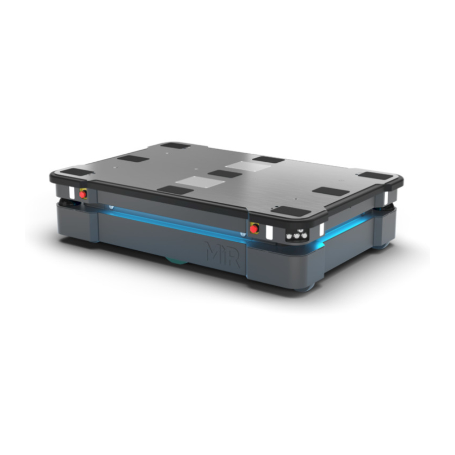
2. Product presentation 2. Product presentation MiR600 is an autonomous mobile robot that can transport loads up to 600 kg indoors within production facilities, warehouses, and other industrial locations where access to the public is restricted. Users operate MiR600 via a web-based user interface, which is accessed through a browser on a PC, smartphone, or tablet. -
Page 11: Main Features Of Mir600
• Efficient transportation of heavy loads The robot is designed to automate transportation of loads up to 600 kg. • Sound and light signals The robot continuously signals with light and sounds, indicating where it will drive and its current status, for example, waiting for a mission, driving to a destination, or destination reached. - Page 12 The following top modules are available for MiR600: • MiR Shelf Lift A lift platform can be mounted on MiR600 enabling it to automate the internal transport of shelves that meet specifications outlines by MiR—see MiR600 Shelf Lift User Guide for the shelf requirements. • MiR Pallet Lift 600 A lift platform can be mounted on MiR600 enabling it to automate the internal transport of US standard 40×48 pallets.
- Page 13 MiR Charge 48V These fully automatic chargers enable MiR robots to recharge their batteries. Together with MiR Fleet, charging of robots can be fully automated, ensuring that robots never run out of power during missions. MiR600 User Guide (en) 08/2021 - v.1.0 ©Copyright 2021: Mobile Industrial Robots A/S.
-
Page 14: External Parts
2. Product presentation 2.2 External parts This section presents the parts of MiR600 that are visible on the outside. Figure 2.1. MiR600 external parts. Table 2.1. Identification of the external parts in Figure 2.1 Pos. Description Pos. Description Left top compartment—see Right top compartment—see Internal parts on page 21 Internal parts on page 21... - Page 15 2. Product presentation Pos. Description Pos. Description detection on page 84 compartment—see Internal parts on page 21 Front safety laser scanner— Front maintenance hatch: Obstacle detection on opens to the front page 84 compartment—see Internal parts on page 21 3D depth cameras: two pcs, Proximity sensors: eight pcs, detect objects in front of the two in each corner behind...
- Page 16 2. Product presentation Figure 2.2. Placement of the identification label. Figure 2.3. Example of a MiR600 identification label. MiR600 User Guide (en) 08/2021 - v.1.0 ©Copyright 2021: Mobile Industrial Robots A/S.
- Page 17 2. Product presentation Nameplate Every MiR application is delivered with a nameplate that must be mounted on the robot. The nameplate of MiR600 identifies the application model and serial number and includes the CE mark, technical specifications, and the address of Mobile Industrial Robots. The nameplate identifies the complete MiR application, for example, a robot with a top module.
- Page 18 2. Product presentation The control panel buttons Figure 2.5. The MiR600 control panel. Table 2.2. Identification of items on the control panel in Figure 2.5 Pos. Description Pos. Description Manual stop button Resume button Power button Operating mode key Manual stop button Pressing this button stops the robot.
- Page 19 2. Product presentation Resume button Pressing this button: • Clears the Emergency or Protective stop state. • Lets the robot continue operating after the Manual stop button was pressed or after the operating mode changes. • Lets the robot start operating after powering up. Color indication: •...
- Page 20 2. Product presentation Remove the Operating mode key during normal operation. The vibrations from the robot's driving may shake the key and plug, and can cause an unwanted Protective stop. Operating modes MiR600 has two operating modes: Manual mode and Autonomous mode. Manual mode In this mode, you can drive the robot manually using the joystick in the robot interface.
-
Page 21: Internal Parts
2. Product presentation 2.3 Internal parts Most internal parts of MiR600 are accessed through maintenance hatches that open to different compartments: • Front compartment • Rear compartment • Side compartments • Top compartments To access the compartments correctly, see Accessing the internal parts on page 39. - Page 22 2. Product presentation Figure 2.6. Internal parts of the front compartment. Table 2.3. Identification of internal parts in Figure 2.6 Pos. Description Pos. Description Robot computer: processes data Switch: enables communication from the sensors and controls between the robot computer, the robot's navigation safety PLC, top interface, and power board...
- Page 23 Motor controller carrier board: band contains the motor controllers and the controller for proximity sensors and light indicators Connection interface for MiR Manual brake release switch: Controller: connect a MiR releases the brakes so the robot Controller to drive the robot can be pushed manually.
- Page 24 2. Product presentation Pos. Description Pos. Description Manual brake release switch on page 27 Dynamic brake contactors: used by the safety system to stop the robot when a safety function is triggered Side compartments The side compartments contain the bogies and drive wheels. To access a side compartment, see Accessing the internal parts on page 39.
- Page 25 2. Product presentation Figure 2.8. Internal parts of the MiR600 left and right side compartments. Table 2.5. Identification of internal parts in Figure 2.8 Pos. Description Pos. Description Connector for the status light Bogie band Drive wheel Battery lock pin (only in left side compartment) Fast-swap battery assembly (only Battery (only in left side...
- Page 26 2. Product presentation Figure 2.9. The top compartments on the robot. Top compartment components The top compartments interfaces are listed in Table 2.6. For detailed information on electrical interfaces, see Interface specifications on page 218. MiR600 User Guide (en) 08/2021 - v.1.0 ©Copyright 2021: Mobile Industrial Robots A/S.
-
Page 27: Manual Brake Release Switch
2. Product presentation Figure 2.10. Interfaces in the top compartments. Table 2.6. Identification of interfaces in Figure 2.10 Pos. Description Pos. Description Ethernet GPIO: General purpose I/O Power Auxiliary safety functions WiFi antenna Auxiliary emergency stop with dummy plug 2.4 Manual brake release switch The Manual brake release switch is located in the rear compartment. - Page 28 2. Product presentation Figure 2.11. Turn the Manual brake release switch clockwise to release the brakes. The mechanical brakes require electrical power to be released, so if the robot is without power, the mechanical brakes cannot be released. You can see if the robot is powered by checking if the Power button on the control panel lights up.
-
Page 29: Warranty
3. Warranty 3. Warranty Mobile Industrial Robots offers a standard warranty on all products. Contact your distributor to see the terms and extent of product coverage. NOTICE Mobile Industrial Robots disclaims any and all liability if MiR600 or its accessories are damaged, changed, or modified in any way. Mobile Industrial Robots cannot be held responsible for any damages caused to MiR600, accessories, or any other equipment due to programming errors or malfunctioning of MiR600. -
Page 30: Safety
4. Safety 4. Safety Read the information in this section before powering up and operating MiR600. Pay particular attention to the safety instructions and warnings. NOTICE Mobile Industrial Robots disclaims any and all liability if MiR600 or its accessories are damaged, changed, or modified in any way. Mobile Industrial Robots cannot be held responsible for any damages caused to MiR600, accessories, or any other equipment due to programming errors or malfunctioning of MiR600. -
Page 31: General Safety Precautions
4. Safety 4.2 General safety precautions This section contains general safety precautions. WARNING If the robot is not running the correct software and is therefore not functioning properly, the robot may collide with personnel or equipment causing injury or damage. •... - Page 32 Using a charging device different from the one supplied by the manufacturer can cause a fire and thereby burn injuries to nearby personnel and damage to the robot and equipment. • Only use an original MiR charger. MiR600 User Guide (en) 08/2021 - v.1.0 ©Copyright 2021: Mobile Industrial Robots A/S.
- Page 33 4. Safety WARNING Lithium battery packs may get hot, explode, or ignite and cause serious injury if they are misused electrically or mechanically. Observe the following precautions when handling and using lithium-ion batteries: • Do not short-circuit, recharge, or connect with false polarity. •...
-
Page 34: Intended Use
MiR600 is intended to be commissioned and used in indoor industrial environments where access for the public is restricted. For details about the environmental conditions in which MiR600 should operate, see specifications for MiR600 on the MiR website. MiR600 is intended to be commissioned according to the guidelines in Commissioning on page 127. - Page 35 • MiR Pallet Lift 600 used with MiR Pallet Rack • MiR EU Pallet Lift 600 used with MiR EU Pallet Rack. • MiR Shelf Lift to transport MiR supported shelves. MiR600 can be used as a partly complete machine as defined in the EU machinery directive with top modules that do not meet the above limitations. Those who design, manufacture, or commission a system that does not meet the limitations of use of MiR600 carry the obligations of a manufacturer and shall ensure a safe design according to EN ISO 12100.
-
Page 36: Users
4. Safety 4.4 Users MiR600 is only intended to be used by personnel that have received training in their required tasks. There are three types of intended users for MiR600: commissioners, operators, and direct users. Commissioners Commissioners have thorough knowledge of all aspects of commissioning, safety, use, and maintenance of MiR600 and have the following main tasks: •... -
Page 37: Foreseeable Misuse
4. Safety All other persons in the vicinity of MiR600 are considered indirect users and must know how to act when they are close to the robot. For example, they must be aware that visibly marked operating hazard zones must be respected. 4.5 Foreseeable misuse Any use of MiR600 deviating from the intended use is deemed as misuse. -
Page 38: Residual Risks
4. Safety Figure 4.1. The warning label must be placed on the robot or top module. 4.7 Residual risks Mobile Industrial Robots has identified the following potential hazards that commissioners must inform personnel about and take all precautions to avoid when working with MiR600: •... -
Page 39: Accessing The Internal Parts
5. Accessing the internal parts 5. Accessing the internal parts Most internal parts of MiR600 are accessed through maintenance hatches that open to different compartments. CAUTION Opening or removing hatches from the robot exposes parts connected to the power supply, risking damage to the robot from a short circuit and personnel getting burnt. -
Page 40: Front Compartment
5. Accessing the internal parts 5.1 Front compartment To open the front compartment, turn the two screws 90° with a flat-head screwdriver, and pull out the compartment. MiR600 User Guide (en) 08/2021 - v.1.0 ©Copyright 2021: Mobile Industrial Robots A/S. -
Page 41: Rear Compartment
5. Accessing the internal parts 5.2 Rear compartment To open the rear compartment, follow these steps: Push the two white buttons to unlock the hatch. MiR600 User Guide (en) 08/2021 - v.1.0 ©Copyright 2021: Mobile Industrial Robots A/S. - Page 42 5. Accessing the internal parts Pull open the hatch. You can now access the Manual brake release switch and MiR Controller interface. To access the motor controller carrier board and dynamic brake contactors, follow these steps: Disconnect the status light connector.
- Page 43 5. Accessing the internal parts Remove the hatch by twisting the two hinges. Remove the seven screws on the rear panel. Loosen the top three screws while holding the bottom of the panel. MiR600 User Guide (en) 08/2021 - v.1.0 ©Copyright 2021: Mobile Industrial Robots A/S.
- Page 44 5. Accessing the internal parts Remove the panel by sliding it downwards and out to access the rear maintenance compartment. MiR600 User Guide (en) 08/2021 - v.1.0 ©Copyright 2021: Mobile Industrial Robots A/S.
-
Page 45: Side Compartments
5. Accessing the internal parts 5.3 Side compartments To open a side compartment, push the two white buttons to unlock the hatch, and pull it open. MiR600 User Guide (en) 08/2021 - v.1.0 ©Copyright 2021: Mobile Industrial Robots A/S. -
Page 46: Top Compartments
5. Accessing the internal parts 5.4 Top compartments To open a top compartment, remove the four screws and lift off the top cover. MiR600 User Guide (en) 08/2021 - v.1.0 ©Copyright 2021: Mobile Industrial Robots A/S. -
Page 47: Getting Started
NOTICE Read Safety on page 30 before powering up MiR600. In some images in this section, the robot is shown with a MiR EU Pallet Lift 600 top module. 6.1 In the box This section describes the contents of the MiR600 box. MiR600 User Guide (en) 08/2021 - v.1.0 ©Copyright 2021: Mobile Industrial Robots A/S. - Page 48 6. Getting started Figure 6.1. The box containing the robot and accessories. The box contains: • The MiR600 robot • A MiR600 document folder containing a USB flash drive and the following printed documents: • MiR600 Quick Start • The CE Declaration of Conformity for your robot •...
-
Page 49: Unpacking Mir600
The USB flash drive in the document folder has the following content: • MiR600 User Guide • MiR600 Quick Start • MiR Network and WiFi Guide • MiR Robot Reference Guide • MiR Robot REST API Reference • Getting the robot online •... - Page 50 6. Getting started Remove the screws that attach the walls of the box to the box lid and the base of the box. Remove the lid from the box, and remove the wooden lath beneath the lid. MiR600 User Guide (en) 08/2021 - v.1.0 ©Copyright 2021: Mobile Industrial Robots A/S.
- Page 51 6. Getting started Place the lid of the box so that you can use it as a ramp. Align the lid so that it is flush with the base of the box. Take the folder with the printed documents and the USB flash drive out of the box. MiR600 User Guide (en) 08/2021 - v.1.0 ©Copyright 2021: Mobile Industrial Robots A/S.
- Page 52 6. Getting started Remove the walls of the box and the protective foam blocks. Cut the protective straps. MiR600 User Guide (en) 08/2021 - v.1.0 ©Copyright 2021: Mobile Industrial Robots A/S.
-
Page 53: Connecting The Battery
6. Getting started Remove the wheel stop board from the pallet to let the robot drive on the ramp. 6.3 Connecting the battery To connect the battery to the robot, you need to open the left side compartment—see Accessing the internal parts on page 39. -
Page 54: Powering Up The Robot
6. Getting started 6.4 Powering up the robot To power up the robot, follow these steps: Ensure that all four Emergency stop buttons are in the released state. Turn an Emergency stop button counter-clockwise to release it. Press the Power button for five seconds. The robot turns on the red signal lights and yellow wavering status lights and starts the software initialization process. -
Page 55: Connecting To The Robot Interface
Once connected, you can configure the robot's settings and connect it to a wireless network. You can purchase a WiFi access point dongle from MiR to be able to connect to the robot wirelessly. Otherwise, you will need to use your own access point or an Ethernet cable to connect to the robot. - Page 56 Connect the WiFi access point dongle to the Ethernet port for a wireless connection, or connect your device directly to the robot using an Ethernet cable. If you are using an access point, connect your device to the access point. The MiR WiFi dongle name has the following format: MiRXXXXXX.
- Page 57 6. Getting started If you want to connect the robot to your local WiFi network, connect the robot to the network as described in Connecting the robot to a WiFi network on the next page. If you want to drive the robot off the pallet immediately, you can do so from the interface as described in Driving the robot in Manual mode on page 61.
-
Page 58: Connecting The Robot To A Wifi Network
6. Getting started Figure 6.2. You can see the software version your robot is running in the bottom left corner of the robot interface. 6.6 Connecting the robot to a WiFi network To communicate with the robot wirelessly without connecting an access point, you can connect the robot to your local WiFi network. - Page 59 6. Getting started To connect the robot to a WiFi network, follow these steps: Connect to your robot as described in Connecting to the robot interface on page 55. Go to System > Settings > WiFi, and select + Add connection. MiR600 User Guide (en) 08/2021 - v.1.0 ©Copyright 2021: Mobile Industrial Robots A/S.
- Page 60 6. Getting started Select the network you want the robot to be connected to, and fill out the displayed fields. MiR600 User Guide (en) 08/2021 - v.1.0 ©Copyright 2021: Mobile Industrial Robots A/S.
-
Page 61: Driving The Robot In Manual Mode
6. Getting started Select + Add connection when you have finished. The robot is now connected to the network. When you are connected to the same network, you can access the robot's interface by entering the IP address displayed under the connection description into your internet browser. - Page 62 6. Getting started To drive the robot in Manual mode, follow these steps: On the robot, turn the Operating mode key to Manual mode (turn it to the right). In the robot interface, select the joystick icon. Select Manual control. The Resume button on the robot starts blinking. On the robot, press the Resume button.
-
Page 63: Checking The Hardware Status
6. Getting started Place your foot in front of the ramp while the robot drives on it to keep the ramp from slipping. 6.8 Checking the hardware status To check that all hardware components work as intended, follow these steps: Sign in to the robot interface—see Connecting to the robot interface on page 55. -
Page 64: Mounting The Nameplate
Check that all elements on the page have the status and that they have green dots on the left. For more information, see Hardware health in MiR Robot Reference Guide on the MiR website. 6.9 Mounting the nameplate Before using MiR600, you must mount its unique nameplate to it. The nameplate contains information specific to your MiR application—see... - Page 65 6. Getting started To mount the nameplate correctly, follow these steps: Locate the right side hatch—see External parts on page 14. Clean the area marked in the image below with a degreasing agent. Mount the nameplate on the cleaned area. MiR600 User Guide (en) 08/2021 - v.1.0 ©Copyright 2021: Mobile Industrial Robots A/S.
-
Page 66: Shutting Down The Robot
6. Getting started 6.10 Shutting down the robot To shut down MiR600, follow these steps: Ensure that the robot is not moving or executing an action. Press the Power button for three seconds. The robot starts the shutdown process. The status lights waver yellow, and the Power button blinks red. - Page 67 6. Getting started When the robot finishes the shutdown process, the status and the signal lights go off. When you shut down the robot for transportation, service, or repair, the battery must be disconnected—see Disconnecting the battery on page 71. MiR600 User Guide (en) 08/2021 - v.1.0 ©Copyright 2021: Mobile Industrial Robots A/S.
-
Page 68: Battery And Charging
7. Battery and charging 7. Battery and charging The robot is powered by a lithium battery that can be charged with a MiR cable charger or a MiR Charge 48V charging station. Table 7.1 identifies the main components of the battery fast-swap assembly and describes the three different positions the assembly can be set to. -
Page 69: Charging The Robot
7.1 Charging the robot This section describes how to charge MiR600 using a MiR cable charger. A MiR cable charger is not part of the MiR600 standard delivery. Contact your distributor for more information. To charge MiR600 with a standard MiR cable charger, you will also need an adapter for the cable to fit to the battery connector. The adapter is supplied by... - Page 70 7. Battery and charging On the robot, pull out the Battery lock pin, and pull the Battery lever down to the bottom position. The battery is now disconnected and unlocked. Grab the handle, and pull the battery out approximately 10 cm. MiR600 User Guide (en) 08/2021 - v.1.0 ©Copyright 2021: Mobile Industrial Robots A/S.
-
Page 71: Disconnecting The Battery
Once the robot has finished charging, reconnect the battery, and close the maintenance hatch. For information about the charging time, see specifications on the MiR website. 7.2 Disconnecting the battery Whenever the robot is to be transported, undergo maintenance, or stored for over 24 hours, you should always disconnect the battery. -
Page 72: Swapping Out The Lithium-Ion Battery
7. Battery and charging 7.3 Swapping out the lithium-ion battery MiR600 is supplied with a removable lithium-ion battery. The robot is delivered with one lithium-ion battery. Contact your distributor if you need more batteries. The left side compartment holds the robot's battery. To access the side compartments, see Accessing the internal parts on page 39. - Page 73 7. Battery and charging To swap out the battery, follow these steps: Pull out the Battery lock pin, and pull the Battery lever down to the bottom level. The battery is now disconnected and unlocked from the robot. Grab the handle and gently pull the battery out. Insert another battery.
-
Page 74: Battery Storage
7.4 Battery storage The battery should be stored in an area at room temperature with a non-condensing relative air humidity—see specifications on the MiR website. Temperatures and humidity below or above the specifications will shorten the service life of the battery. -
Page 75: Battery Disposal
7. Battery and charging Battery state of charge Power save mode timeout Maximum storage time 1 week 15 months 1 week 12 months 1 week 6 months 4 hours 2 months 4 hours 1 month The battery percentage displayed in the robot interface is based on when the robot will shut down due to low voltage. - Page 76 7. Battery and charging Figure 7.2. Battery disposal symbols. MiR600 User Guide (en) 08/2021 - v.1.0 ©Copyright 2021: Mobile Industrial Robots A/S.
-
Page 77: Security
MiR600 communicates all data over the network that it is connected to. It is the responsibility of the commissioner to ensure that it is connected to a secure network. MiR recommends conducting an IT-security risk assessment before commissioning the robot. - Page 78 8. IT security Understanding MiR software versions MiR uses the Major.Minor.Patch.Hot fix format to version software. For example, 2.8.1.1 means that the software is based on the second major release, the eighth minor release of the major version, the first patch release of the minor version, and, in this example, a single hot fix is included too.
-
Page 79: Navigation And Guidance System
9. Navigation and guidance system 9. Navigation and guidance system The navigation and guidance system is responsible for driving the robot to a goal position while avoiding obstacles. This section describes the processes and components involved in the robot's navigation and guidance system. 9.1 System overview The purpose of the navigation and guidance system is to guide the robot from one position on a map to another position. - Page 80 9. Navigation and guidance system Figure 9.1. Flow chart of the navigation and control system. The user provides the necessary input for the robot to generate a path to the goal position. The robot executes the steps in the navigation loop until it reaches the goal position and stops by engaging the brakes.
-
Page 81: User Input
9. Navigation and guidance system 9.2 User input To enable the robot to navigate autonomously, you must provide the following: • A map of the area, either from a .png file or created with the robot using the mapping function—see Creating and configuring maps on page 130. - Page 82 9. Navigation and guidance system Figure 9.3. The global path is shown with the blue dotted line that leads from the start to the goal position. The global path is created only at the start of a move action or if the robot has failed to reach the goal position and needs to create a new path.
-
Page 83: Local Planner
9. Navigation and guidance system 9.4 Local planner The local planner is used continuously while the robot is driving to guide it around obstacles while still following the global path. Figure 9.5. The global path is indicated with the dotted blue line and is visible on the map. The local path is indicated with the blue arrow, showing the robot driving around a dynamic obstacle. -
Page 84: Obstacle Detection
9. Navigation and guidance system Figure 9.6. The local planner usually follows the global planner, but as soon as an obstacle gets in the way, the local planner determines which immediate path will get the robot around the obstacle. In this case, it will likely choose the path indicated with a green arrow. - Page 85 9. Navigation and guidance system Table 9.1. Description of how the robot sees obstacles with its sensors What the laser scanners What a human sees What the 3D cameras see A chair placed in the In the robot interface, the The 3D cameras detect corner of a room is red lines on a map are...
- Page 86 9. Navigation and guidance system Figure 9.7. The two safety laser scanners together provide a full 360° view around the robot. When mapping, the safety laser scanners' view is reduced to 20 m to ensure that maps get the highest possible quality. The laser scanners have the following limitations: •...
- Page 87 9. Navigation and guidance system If you are using the robot in an area with walls made of glass or reflective material, mark the walls as Forbidden zones on the map, not as walls—see Creating and configuring maps on page 130. Walls on the map that the robot cannot detect will confuse the robot's navigation system.
- Page 88 9. Navigation and guidance system Figure 9.8. The two 3D cameras can see objects up to 1800 mm above floor height at a distance of 1200 mm in front of the robot and have a horizontal field of view of 114°. The 3D cameras have the following limitations: •...
- Page 89 9. Navigation and guidance system • The cameras are not reliable at determining depth when viewing structures with repetitive patterns. • The cameras may detect phantom obstacles if they are exposed to strong direct light. Proximity sensors Using infrared light, the proximity sensors point downwards and detect low objects around the corners of the robot outside the field of view of the safety scanners and 3D cameras.
- Page 90 9. Navigation and guidance system The following points describe the main features of the proximity sensors once they are enabled: • The proximity sensors are constantly active. • Because of the sensors' limited range, the data from them is only useful when the robot is standing still or moving at low speeds.
- Page 91 9. Navigation and guidance system Besides preventing collision with low objects placed close to the robot upon movement after standstill, the proximity sensors can also improve driving performance in the following situations: • When the robot is docking, reversing, turning sharply, or pivoting at reduced speeds, the robot is more likely to detect and avoid low objects.
-
Page 92: Localization
9. Navigation and guidance system 9.6 Localization The goal of the localization process is for the robot to determine where it is currently located on its map. The robot has three inputs for determining where it is: • The initial position of the robot. This is used as a reference point for the methods used to determine the robot position. - Page 93 9. Navigation and guidance system Failed localization Successful localization Figure 9.10. In a failed localization, the robot cannot determine a position where the red lines (laser scanner data) align with the black lines on the map. When the robot can localize itself, it determines a cluster of likely positions, indicated in the images above as blue dots.
-
Page 94: Motor Controller And Motors
9. Navigation and guidance system • The robot must be able to detect the static landmarks that are marked on the map to be able to approximate its current position. Make sure there are not too many dynamic obstacles around the robot so that it cannot detect any static landmarks. Cannot detect any static landmarks Can detect enough static landmarks •... - Page 95 9. Navigation and guidance system Figure 9.11. The robot has reached the goal position and stops by engaging the dynamic brake function. Once the robot has stopped, the mechanical brakes are enabled. These brakes are used to keep the robot in place once it has stopped. You can compare the mechanical brakes with the parking brake or hand brake in a car.
-
Page 96: Safety-Related Functions And Interfaces
10. Safety-related functions and interfaces 10. Safety-related functions and interfaces The robot's safety system is designed to mitigate significant hazards which could lead to injury, for example, stopping the robot if a person is in its path. MiR600 is equipped with a range of built-in safety-related functions as well as safety-related electrical interfaces designed for integration with a top module. - Page 97 10. Safety-related functions and interfaces • Emergency stop • Manual stop The last three types of stop are monitored by the safety PLC. Operational stop The robot is in Operational stop when it is stopped through the robot interface either through a mission action or by pausing the mission.
- Page 98 10. Safety-related functions and interfaces Emergency stop The robot enters Emergency stop when an Emergency stop button has been pressed physically. When you press the Emergency stop button, internal safety contactors are switched so the robot's top application and all moving parts of the robot do not receive power.
- Page 99 10. Safety-related functions and interfaces CAUTION Emergency stop buttons are not designed for frequent use. If a button has been used too many times, it may fail to stop the robot in an emergency situation, and nearby personnel may be injured by electrical hazards or collision with moving parts.
- Page 100 10. Safety-related functions and interfaces Safety-related functions The following functions are integrated within the robot itself and cannot be modified or used with other applications. The following list introduces the main safety-related functions integrated in MiR600: • Personnel detection This function ensures that the robot stops before it collides with personnel or an object. If the laser scanners detect an object or person within a defined Protective field, the robot is brought to a stop.
- Page 101 The reduced speed function can be connected to a top module, enabling it to make the robot reduce its speed to 0.3 m/s. This is for example used by MiR lifts to ensure that the robot does not drive fast when the lift is raised.
-
Page 102: Personnel Detection
10. Safety-related functions and interfaces Figure 10.3. Overview of components involved in each safety function and interface. When a safety function is triggered, the safety PLC switches the STO contactors so the motors and power supply to the top module no longer receive power. - Page 103 10. Safety-related functions and interfaces Drives when the area is clear Stops when an obstacle is detected Figure 10.4. Personnel detection ensures that the robot drives when its path is clear and stops if an obstacle is detected within its Protective field. The safety laser scanners are programmed with two sets of Protective fields. One field set is used when the robot is driving forward and the other when it is driving backward.
- Page 104 10. Safety-related functions and interfaces Field set when driving forward The following table shows speeds and the field range when driving forward. The table describes the length of the Protective field in front of the robot in different cases. Each case is defined by a speed interval that the robot may operate at.
- Page 105 10. Safety-related functions and interfaces Field set when driving backward The field set for driving backward is the same as the field set for driving forward. The colors and cases in Table 10.2 correspond to the field set shown in Figure 10.6. Table 10.2.
- Page 106 10. Safety-related functions and interfaces NOTICE Scanners measure distances to diffuse reflections, which means that a tolerance is added to the Protective field sets to secure a safe detection of persons crossing the Protective field sets. The tolerance distance is 65 mm. Muted Protective fields When performing tasks that require the robot to move very close to surrounding objects, the robot can be configured to mute the Protective fields.
- Page 107 10. Safety-related functions and interfaces Manually muting the Protective fields There are two ways you can mute the Protective fields using the robot interface: • Adding the Mute protective fields action to a mission: Enable Mute protective fields under System > Settings > Features—see System settings on...
-
Page 108: Overspeed Avoidance
10. Safety-related functions and interfaces The only marker that does not mute the Protective fields are L-markers. The Protective field sets are muted from when the docking starts and until the robot has undocked and has started a new action that requires the robot to plan a path. The Protective field sets will remain muted during any Relative move action that come right after the docking action. - Page 109 In order to bring the robot out of Emergency stop, the robot must be fitted with another closed connection or a dummy plug. Dummy plugs are supplied by MiR. Additionally, the connection interface for the MiR controller in the rear compartment also has a dummy plug that must be connected to keep the circuit closed.
-
Page 110: Emergency Stop Circuit
10. Safety-related functions and interfaces Pos. Description Pos. Description circuit on the next page Rear-right Emergency stop Connection interface for MiR button controller with dummy plug Rear-left Emergency stop button Front-left Emergency stop button Safety PLC 10.5 Emergency stop circuit The Emergency stop circuit goes through the four Emergency stop buttons in MiR600—see... - Page 111 10. Safety-related functions and interfaces Emergency stop button released Emergency stop button pushed Emergency stop circuit faulty Figure 10.8. If the input pins deliver 24 V to the robot, it can operate. When you push a connected Emergency stop button, both pins deliver 0 V, and the robot enters Emergency stop. If the pins do not deliver the same input, the robot enters Protective stop until the circuits are fixed.
-
Page 112: Safeguarded Stop
10. Safety-related functions and interfaces In the Auxiliary emergency stop interface, pins 1 and 2 deliver 24 V from the safety PLC, and pins 3 and 4 connect to the Emergency stop circuit inputs of the safety PLC. 24 V must be delivered to pins 3 and 4 for the robot to operate. ... - Page 113 10. Safety-related functions and interfaces Signal to enable operation Signal to enter Protective stop Signal to enter Protective stop Figure 10.9. If both pins deliver 24 V to the robot, it can operate. If either or both of the pins deliver 0 V, the robot enters Protective stop.
-
Page 114: Locomotion
10. Safety-related functions and interfaces 10.7 Locomotion The Locomotion interface is used to signal to a top module that the robot is driving. This function uses two output pins, where both pins deliver 0 V when the robot is driving and 24 V when the robot is stopped. - Page 115 10. Safety-related functions and interfaces The inputs are intended to enable the top module to bring the robot into Emergency stop. When both inputs deliver 24 V, the robot can operate, but as soon as either or both of the inputs deliver 0 V, the robot enters Emergency stop.
- Page 116 10. Safety-related functions and interfaces Not in Emergency stop System emergency stop inputs are 0 V Emergency stop button on robot is System emergency stop inputs are pressed unequal Figure 10.11. There are four cases described above. They illustrate respectively: 1. the robot is not in Emergency stop so the output is 24 V, 2.
-
Page 117: Reduced Speed
10. Safety-related functions and interfaces been pressed, 4. the robot is in Emergency stop because the inputs are unequal. In the Auxiliary safety function interface, pins 7 and 8 are used for the output and pins 9 and 10 are used for the input of the System emergency stop function. 10.9 Reduced speed The Reduced speed interface is used to signal to the robot that it must drive at a reduced speed of 0.3 m/s. This is the same speed used when the robot mutes its Protective fields. -
Page 118: Safety Functions Performance Overview
10. Safety-related functions and interfaces The Shelf mode interface is a signal specifically used when MiR Shelf Lift is mounted to the robot. The signal activates when the robot is carrying a shelf, triggering the robot to change to the shelf specific Protective field sets and use the laser scanners to check that the four shelf legs are detected around the robot, ensuring that the robot has successfully picked up the shelf. - Page 119 10. Safety-related functions and interfaces PFHd, PL, Function Reset Triggering event Reaction name function architecture page 114. Overspeed The speed of the Category 0 stop Press the PFHd: robot exceeding (IEC 60204) and Resume 5.2 × 10 2.10 m/s or the mechanical button on the difference in spring-applied...
- Page 120 10. Safety-related functions and interfaces PFHd, PL, Function Reset Triggering event Reaction name function architecture 0.3 m/s while the mechanical button on the Protective fields spring-applied robot. are muted. brakes engage. Architecture: Category 3 Safeguard External device Category 0 stop Resumes PFHd: stop delivering 0 V to...
- Page 121 10. Safety-related functions and interfaces PFHd, PL, Function Reset Triggering event Reaction name function architecture brakes engage. Architecture: Category 1 System External device Category 0 stop When PFHd: emergency delivering 0 V to (IEC 60204) and external 3.7 × 10 stop the System mechanical signals are...
-
Page 122: Safety Stop
10. Safety-related functions and interfaces 10.12 Safety stop There are two pairs of contactors used to stop MiR600: the STO (Safe Torque Off) contactors and the dynamic brake contactors. These are controlled by the safety PLC and are used when the robot goes into Protective or Emergency stop. - Page 123 10. Safety-related functions and interfaces • Signal lights The signal lights at the front and back of the robot show if the robot is about to turn a corner or go backward. Front lights are white and rear lights are red. Right and left turns are indicated by blinking.
- Page 124 Charging at charging station White wavering Prompt user / Waiting for user's response Cyan wavering (robots Waiting for MiR Fleet resource or for another MiR robot to connected to MiR Fleet move only) When the robot's battery reaches a critically low level of power (0-1%), the ends of the status lights flash red.
- Page 125 10. Safety-related functions and interfaces When the robot drives with muted Protective fields, for example, when docking to a charging station, all signal lights blink yellow. Speakers Setup > Sounds, you can upload new sounds to the robot or edit the volume and length of the default sounds.
- Page 126 10. Safety-related functions and interfaces CAUTION Unaware personnel may not see the robot in certain situations and risk colliding with the robot. This may result in injury to personnel or damage to equipment. • Make sure to adjust the volume of the robot's warning sounds so they are audible in the robot's work environment.
-
Page 127: Commissioning
11. Commissioning 11. Commissioning This section describes how to commission MiR600. Commissioning should be done without any load on the robot, except when doing brake tests where the robot should have a load equaling the heaviest load it will be driving with. Only persons assigned with the commissioning task should be present during commissioning. - Page 128 Temperature and humidity Temperatures outside of the approved temperature range can affect the performance and durability of the robot—see specifications on the MiR website. This is especially relevant for the robot's battery—see Battery storage on page 74.
-
Page 129: Risk Assessment
Make sure the environment MiR600 operates in is suitable for its IP rating—see specifications on the MiR website. Static landmarks and dynamic obstacles The robot uses static landmarks to navigate by. -
Page 130: Creating And Configuring Maps
11. Commissioning A risk assessment of the application must be used to determine the adequate information for users. Special attention to at least the following Essential Health and Safety Requirements (EHSR) from Directive 2006/42/EC must be taken: • 1.2.2 Control devices •... - Page 131 11. Commissioning Figure 11.1. Example of a map without any added zones, positions, or markers. The robot must have a map for every area that it operates in. It is important to create robust and reliable maps for the robot to perform effectively and safely. MiR600 User Guide (en) 08/2021 - v.1.0 ©Copyright 2021: Mobile Industrial Robots A/S.
- Page 132 In general, we recommend that maps should not exceed an area of 300 x 300 meters. • You can connect maps using map transitions—see MiR Robot Reference Guide, or ask your distributor for the guide How to set up transitions between maps.
- Page 133 11. Commissioning Each site also includes other elements in the interface, such as missions. For the full list of what is included in a site, see MiR Robot Reference Guide on the MiR website. Creating a map To create a new map, you drive the robot around its intended work environment while its sensors gather data to generate a map from.
- Page 134 11. Commissioning For more information on creating a map, see the Creating your first map- course in MiR Academy on the MiR website. Contact your distributor for access to MiR Academy. Cleaning up a map The robot navigates best when using a clean map with as little noise as possible. Figure 11.3 is an example of what a map can look like after the mapping process but where it still needs further editing.
- Page 135 11. Commissioning There are several tools in the robot interface that you can use to improve your map: • Erase uploaded or recorded data when editing walls to remove walls that were created around dynamic obstacles and noise on the map. Noise refers to recorded data that originates from interfering elements.
- Page 136 For more information about what each zone does, see MiR Robot Reference Guide on the MiR website, or ask your distributor for the guide How to use zones on a map.
- Page 137 11. Commissioning NOTICE The robot prioritizes the instructions it receives in the following order: Instructions from zones. Instructions from mission actions. Instructions from system settings (except from the setting Maximum allowed speed, which is never overruled by neither zones nor mission actions).
- Page 138 11. Commissioning Highly dynamic areas A highly dynamic area is an area where objects are moved frequently. This could be a production area where pallets and boxes are often moved back and forth. Issue: The robot will stop if a person steps out in front of it. In a transient work flow area, the robot will stop and reassess its paths many times a day, thereby wasting valuable time.
- Page 139 11. Commissioning Doorways Going through narrow doorways can cause problems for the robot's global planner since the robot must drive closer to wall edges than it usually would. It can also be hazardous for the people working near the robot, as they might not see the robot coming. Issue: The robot does not plan its global path through narrow doorways, since this will bring the robot too close to a known obstacle.
- Page 140 11. Commissioning Shelves Shelves are often placed in a certain height above the floor on four (or more) posts and will often appear as dots on a map for the robot. This may cause the robot to believe that there is enough space (if the posts are far enough apart) below the shelves to pass through.
-
Page 141: Markers
If there isn't enough space for robots to pass each other, you can use a Limit-robots zone to specify that only one robot may drive down the corridor at a time. To use Limit-robots zones, your robots must be connected to MiR Fleet. 11.4 Markers Markers are defined as X-Y coordinates on a map that mark locations where you want the robot to travel to. - Page 142 11. Commissioning this entity. You should always use markers when it is important that the robot is positioned accurately relative to an object in the work environment, such as load transfer stations and work stations. Docking to markers Markers require the robot to do a docking sequence. When the robot is docking, it uses its safety laser scanners to detect the marker and drives itself to the correct position relative to the detected marker.
- Page 143 Undocking from markers A MiR robot can undock from markers automatically. When undocking, the robot reverses from the marker until it is outside of the undocking area—see Figure 11.9. The robot will keep muting its Protective fields while it undocks. Once the robot begins a new action that requires it to plan a new path, the Protective fields are activated again, and the robot continues normal operation.
- Page 144 11. Commissioning To enable automatic undocking from markers, go to System > Settings > Docking enable the parameter Undock from markers You can also modify the size of the undocking area under System > Settings > Docking using the parameters Docked at marker reverse distance Docked at marker side threshold—see Table 11.1.
- Page 145 Relative move action. Types of markers There are four standard marker types that all MiR robots can use: V, VL, L, and Bar-markers. MiR600 User Guide (en) 08/2021 - v.1.0 ©Copyright 2021: Mobile Industrial Robots A/S.
- Page 146 11. Commissioning V-marker is a small, V-shaped marker that is designed for the robot to either dock to so its front or its rear is facing the marker. The V-marker is the simplest marker available for the robot. It consists of a V shape with an interior angle of 120° and sides of 150 mm. The robot must dock straight toward the inside of the V.
- Page 147 The marker is shaped liked an L with a defined angle of 90˚ and the dimensions 400 mm × 600 mm. The robot must dock so the longer side of the L-marker is parallel with the right and left sides of the robot.
-
Page 148: Positions
11. Commissioning Figure 11.14. The icon used for Bar-markers in the interface and an illustration of how robots can dock to the marker. A few centimeters between all the types of markers should make docking possible. Determine during commissioning if more space is required. For further information on markers, contact your distributor for the guide How to create and dock to V-markers, VL-markers, L-markers, and Bar-markers. -
Page 149: Creating Missions
There are different types of positions depending on whether the robot is part of a fleet or drives with top modules, but the standard position that is available in all MiR applications is the Robot position. This position has no special features, it simply marks a location where you want to be able to send the robot to. - Page 150 To create efficient missions, you should first familiarize yourself with the available actions in MiR Robot Interface—see the MiR Robot Reference Guide— and then consider: • Which tasks do I want the robot to perform? •...
- Page 151 11. Commissioning Figure 11.15. You can use variables to make a mission where you can set a parameter in one of the actions each time you use the mission (either when you add the mission to the mission queue or embed it in another mission).
- Page 152 For more information on building robust missions, see the Mission robustness videos in MiR Academy on the MiR website. Contact your distributor for access to MiR Academy. MiR600 User Guide (en) 08/2021 - v.1.0 ©Copyright 2021: Mobile Industrial Robots A/S.
-
Page 153: Creating A Footprint
For more information on creating missions, see MiR Robot Reference Guide and the Making your first missions-course in MiR Academy on the MiR website. Contact your distributor for access to MiR Academy. 11.7 Creating a footprint The footprint specifies how much space the robot occupies, including any loads or top modules. - Page 154 11. Commissioning Default footprint Larger footprint Figure 11.17. Examples of the default robot footprint and an extended footprint. The values displayed along each line is the length of the edge in meters. The number of footprints you need to define depends on: •...
- Page 155 For a more thorough guide to creating footprints, contact your distributor for the guide How to change the robot footprint. For more information about the footprint editor, see MiR Robot Reference Guide on the MiR website. MiR600 User Guide (en) 08/2021 - v.1.0 ©Copyright 2021: Mobile Industrial Robots A/S.
- Page 156 11. Commissioning If you want to change the footprint in a mission, use the Set footprint action found under the Move action group. This is used to change the footprint when the robot picks up a load that extends the footprint or places a load and the footprint returns to the default. MiR600 User Guide (en) 08/2021 - v.1.0 ©Copyright 2021: Mobile Industrial Robots A/S.
-
Page 157: Using Operating Hazard Zones
11. Commissioning If you want to edit the default footprint of the robot, for example if the mounted top module is larger than the robot, go to System > Settings > Planner, and select a new footprint under Robot footprint. 11.8 Using operating hazard zones Operating hazard zones are areas that must be visibly marked to comply with safety standards in EN 1525 and ISO 3691-4. - Page 158 Sound and light zones can be used to add acoustic and visual warnings when the robot drives into the zones. For more information about zones, see the MiR Robot Reference Guide. Docking to a marker When docking to a marker, the robot mutes its Protective fields temporarily—see Markers page 141.
-
Page 159: Making A Brake Test
11. Commissioning Figure 11.18. The striped black and yellow line identifies the required operating hazard zone around the marker. The robot is placed on the Entry position to the marker. You must mark the floor area one meter around the docking marker and the robot when it is at the Entry position. -
Page 160: Creating User Groups And Users
The decline of the surface the robot drives on Because of this, it is not possible to predetermine the exact braking distance of MiR robots. The distance has to be determined in the environment and under the driving conditions the robot will be operating in. - Page 161 What permissions should the different users have? • What functions or widgets should be available for the different users? For more details on users and dashboards, see MiR Robot Reference Guide on the MiR website. Create user groups Setup > User groups, you can create specific user groups with specific access to different parts of the robot interface.
- Page 162 11. Commissioning Figure 11.20. You can select the specific parts of the robot interface that the user group has access to. Create users Setup > Users, you can create new users and select: • Which user group they belong in. •...
-
Page 163: Creating Dashboards
11. Commissioning Figure 11.21. When you create a user, you must fill out the fields shown in this image. Table 11.2. Examples of which users MiR recommends should be able to edit which features Feature User group Controlling the robot manually... - Page 164 11. Commissioning For more details on how to use and create dashboards, see MiR Robot Reference Guide on the MiR website. A dashboard is made up of a number of widgets, each representing a feature in the system, for example a particular mission, the map the robot is operating on, or the current mission queue.
-
Page 165: Updating Software
Try to include only the necessary widgets. 11.12 Updating software MiR continuously updates the software the robots use, either to fix issues, to improve existing features, or to introduce new features. Each software release is issued with a release note explaining the content of the update and its target audience. -
Page 166: Creating Backups
Backups take up some of your robot's memory space. It is a good idea to remove any old backups you are certain you will not need in the future. For more information on how to create, roll back, and delete backups, see MiR Robot Reference Guide on the website. - Page 167 11. Commissioning Only the basic system settings are explained in this section—see MiR Robot Reference Guide on the MiR website for more information. NOTICE The robot prioritizes the instructions it receives in the following order: Instructions from zones. Instructions from mission actions.
- Page 168 11. Commissioning Remember to restart the robot if you have made any changes to the system settings. Planner In the Planner section, you set the basic parameters for driving the robot. This section refers to the local and global planner functions. For more information on the robot's path planners, see Global planner on page 81 Local planner on...
- Page 169 11. Commissioning Robot height defines the height of the robot including top modules. Use this setting if your robot operates permanently with a top module that makes the combined robot application higher than the robot itself. This prevents the robot from colliding with obstacles from above.
- Page 170 11. Commissioning Line-following disabled Line-following enabled Figure 11.25. Example of where the robot might benefit from using a Line-following configuration. When there isn't enough space for the robot to go around an obstacle, it will often spend more time trying to maneuver around the obstacle and correct its trajectory afterward than it would have just waiting for the obstacle to move out of the way.
- Page 171 11. Commissioning Figure 11.26. Change the parameters regarding docking to and from markers in the Docking section. Undock from markers, you can select if the robot should undock from a marker before it starts moving from a docked position. It is usually best to set this setting to True to prevent the robot from going into Protective stop when moving away from markers.
- Page 172 11. Commissioning Safety system In the Safety system section, you can change which warning sound the robot should emit when it mutes its Protective fields and how loud the sound should play. Figure 11.27. In the Safety system section, you can change the robot's warning sound. Select Muted protective fields sound to change the warning sound that is played when the...
- Page 173 Enable this feature if the robot drives with an application from Universal Robots. Fleet makes the robot visible for MiR Fleet. Enable this feature if the robot is part of a fleet. MiR600 User Guide (en) 08/2021 - v.1.0 ©Copyright 2021: Mobile Industrial Robots A/S.
- Page 174 I/O modules. This can be used for setting PLC registers and trigger missions. Enable this feature if the robot uses I/O modules, for example, when any MiR top module is mounted to the robot. Mute protective fields enables an action to mute the robot's Protective fields in missions.
-
Page 175: Usage
12. Usage 12. Usage The main way to use MiR600 is through missions that you create. In the following sections you will find practical examples of how missions can be tailored to different tasks. The examples include: • Setting markers and positions on the map. •... - Page 176 12. Usage Once the robot is localized, you can insert a marker on the map. In this example, we are using a VL-marker . To create a marker, follow these steps: Place your physical marker where you want the robot to dock. Manually drive the robot to the marker so the robot is facing the marker.
- Page 177 12. Usage Go to Setup > Maps, and select Edit for the active map. Within the editor, select Markers in the Object-type drop-down menu, and then select Draw new marker in the editor tools. MiR600 User Guide (en) 08/2021 - v.1.0 ©Copyright 2021: Mobile Industrial Robots A/S.
- Page 178 12. Usage In the Create marker dialog box, name the marker. Under Type, select your marker type. In this case, a VL-marker is used. Then select Detect marker. The X, Y, and orientation values will automatically be filled out with the current position of the robot.
- Page 179 12. Usage • To change where the robot stops relative to the marker, you can adjust the offsets. • The X-offset moves the robot closer to or further from the marker in meters. • The Y-offset moves the robot further to the left or right of the marker in meters. •...
-
Page 180: Creating Positions
12. Usage For more information about the marker offsets, see How to create and dock to V-markers, VL-markers, L-markers, and Bar-markers. Select to create the marker. The marker is now visible on the map. You can make the robot dock to the marker by selecting it on the map and selecting The marker can also be used in missions. - Page 181 12. Usage In the robot interface, go to the map editor of the map where you want to create a position. This is done by going to Setup > Maps and selecting Edit next to the map you would like to work on. In the Object-type drop-down menu, select Positions, and then select Draw a new position...
- Page 182 12. Usage Name the position. Under Type, select which type of position you want to make. In this example we are making a Robot position. Select to create the position. The position is now visible on the map. You can send the robot to the position by selecting it on the map and selecting to.
-
Page 183: Creating The Mission Prompt User
12. Usage 12.3 Creating the mission Prompt user Prompt user actions are used for prompting the user with a question on how the robot should proceed. Prompt user is an example mission that uses a Prompt user action that lets you choose whether to send the robot to one position or another. - Page 184 12. Usage Select the following actions: • In the Logic menu, select Prompt user. • In the Move menu, select Move. • In the Move menu, select Move. The following steps describe which parameters each action should be set to. To modify the parameters, select the gearwheel at the right end of the action line to open the action dialog box.
- Page 185 12. Usage In the Prompt user action, drag a Move to action under the box and a Move to action under the box. MiR600 User Guide (en) 08/2021 - v.1.0 ©Copyright 2021: Mobile Industrial Robots A/S.
- Page 186 12. Usage In the first Move to action, under Position, select p1. MiR600 User Guide (en) 08/2021 - v.1.0 ©Copyright 2021: Mobile Industrial Robots A/S.
-
Page 187: Creating The Mission Try/Catch
12. Usage In the second Move to action, under Position, select p2. The mission should look like this: Select Save to save the mission. 12.4 Creating the mission Try/Catch Try/Catch actions are used to handle mission errors. When you use a Try/Catch action, you can define what the robot should do if, at any point, it fails to execute its main mission. - Page 188 12. Usage providing an alternative course of action if the main mission fails. Try/Catch is a mission example where the robot runs the mission Prompt user created in Creating the mission Prompt user on page 183, and if the robot for some reason fails to complete the mission, the robot plays a sound.
- Page 189 12. Usage Select the following actions: • In the Error handling menu, select Try/Catch. • Select the Prompt user mission you have made. The mission menu you have saved the mission under will figure as a menu in the mission editor. The menus contain both missions and actions.
- Page 190 12. Usage The following steps describe which parameters each action should be set to. To modify the parameters, select the gearwheel at the right end of the action line to open the action dialog box. When you have set the parameters, select Validate and close.
- Page 191 12. Usage Drag the Play sound action under the Catch box under Try/Catch. MiR600 User Guide (en) 08/2021 - v.1.0 ©Copyright 2021: Mobile Industrial Robots A/S.
- Page 192 12. Usage In the Play sound action, set the parameters as follows: • Sound: Select Beep. • Volume: Enter the value 80. This is approximately 64 dB. • Mode: Select Custom length so you can enter the duration of time the sound is played.
-
Page 193: Creating The Mission Variable Docking
12. Usage Select Save to save the mission. 12.5 Creating the mission Variable docking All mission actions that require the user to specify the value of a parameter when they choose to use the mission have the option of defining a variable. If you use a variable in a mission, when you add the mission to the mission queue or embed it inside another mission, you must select a value for the parameter where the variable is used. - Page 194 12. Usage • Created several markers that the robot can dock to—see Creating markers on page 175. To create the mission, follow these steps: Go to Setup > Missions. Select Create Mission. Name the mission Variable docking. Select the group and site you want it to belong to. Select Create mission.
- Page 195 12. Usage Select the following actions: • In the Move menu, select Move. • In the Safety system menu, select Mute protective fields. • In the Move menu, select Docking. • In the Logic menu, select Wait. • In the Move menu, select Relative move.
- Page 196 12. Usage In the Move action, make the parameter Position a variable that can be set each time you use the mission. The following steps describe how to create a variable: Under Position, select Variables Select Create variable in the upper-right corner. Name the variable Marker.
- Page 197 12. Usage Under Position type, select Entry. This will make the robot move to the entry position of the marker. If the parameter Position type does not show up at first, select Validate and close, and then open the action dialog box again. MiR600 User Guide (en) 08/2021 - v.1.0 ©Copyright 2021: Mobile Industrial Robots A/S.
- Page 198 12. Usage In the Mute protective fields action, set the parameters as follows: • Sound: Select Default • Front: Create a variable titled Mute fields. • Rear: Create a variable titled Mute fields. • Sides: Create a variable titled Mute fields. MiR600 cannot mute specific Protective fields; you must either mute all or none of the fields.
- Page 199 12. Usage Drag the Docking action into the Mute protective fields action, and under Marker position, create another variable titled Marker. If two variables share the same name, the value you select for that variable will be applied both places. In this case, by using the variable Marker in two places, you ensure that the robot docks to the same marker that it moved to in the first action.
- Page 200 12. Usage Drag the Wait action into the Mute protective fields action, and under Time, create another variable titled Time. Drag the Relative move action into the Mute protective fields action, and under X, enter -2. This will make the robot move two meters back to undock from the marker. MiR600 User Guide (en) 08/2021 - v.1.0 ©Copyright 2021: Mobile Industrial Robots A/S.
-
Page 201: Testing A Mission
12. Usage Select Save to save the mission. 12.6 Testing a mission After you create a mission, always run the mission to test that the robot executes it correctly. NOTICE Always test missions without load to minimize potential hazards. To run a mission, follow these steps: Go to Setup > Missions. - Page 202 12. Usage We recommend running the mission 5-10 times to ensure that it runs smoothly. If something interrupts the mission, use a Try/Catch action in that step of the mission and decide what the robot has to do if a mission action fails.
-
Page 203: Applications
13. Applications You can install top modules on top of MiR600 for specific applications. For more information about top modules from MiR, see MiR Top Modules on the MiR website. For more information about top modules from third parties, see MiRGo on the MiR website. - Page 204 13. Applications Figure 13.1. Mounting holes on the top of MiR600. Certain top modules may require the installation of an extra Emergency stop button. Perform a risk assessment according to standard ISO 12100—see Risk assessment on page 129. CAUTION Certain top modules may lead to new hazards and increased risks that cannot be eliminated or reduced by the risk reduction measures applied by Mobile Industrial Robots.
- Page 205 13. Applications CAUTION MiR600 may tip over if weight and payload specifications are not met, risking damage to equipment or injury to nearby personnel. • Stay within the specifications for weight and the total payload’s center of gravity—see Payload distribution on page 216.
-
Page 206: Maintenance
14. Maintenance 14. Maintenance The following maintenance schedules give an overview of regular cleaning and parts replacement procedures. It is the responsibility of the operator to perform all maintenance tasks on the robot. The stated intervals are meant as guidelines and depend on the operating environment and frequency of usage of the robot. - Page 207 14. Maintenance Table 14.1. Regular weekly checks and maintenance tasks Parts Maintenance tasks Robot top cover and Clean the robot on the outside with a damp cloth. maintenance Do not use compressed air to clean the robot. hatches Laser scanners Clean the optics covers of the scanners for optimum performance.
-
Page 208: Regular Checks And Replacements
14. Maintenance Parts Maintenance tasks Drive wheels (the Remove dirt with a damp cloth, and make sure nothing is two middle wheels) entangled in the wheels. Wipe away an grease that may have leaked from the roller bearings. Status lights Check if the LED light band is intact. - Page 209 14. Maintenance Part Maintenance Interval Robot In the robot interface under Check monthly and after hardware Monitoring > Hardware health, commissioning or if you make check if there are any warnings any changes to the robot setup. (marked with yellow). Front, rear, Check mounting.
- Page 210 14. Maintenance Part Maintenance Interval Drive wheels Lubricate the roller bearings. Lubricate the roller bearings (the two yearly. To lubricate the bearings, attach middle wheels) a grease pump to the grease fitting on one of the drive wheels, and apply at least 11 g of Rocol Foodlube Hi-Temp 2 or another lubricant with the same properties.
- Page 211 How to calibrate a D435 To test the cameras, see the 3D camera. guide How to test if the 3D cameras are working on MiR robots Proximity Check for dust or dirt, and clean Check weekly.
-
Page 212: Battery Maintenance
14. Maintenance 14.3 Battery maintenance The battery is generally maintenance-free but should be cleaned if it gets very dirty. Before cleaning, the battery must be removed from any power source. Only use a dry and soft cloth to clean the housing of the battery, and do not use abrasives or solvents. For storage of the battery, see Battery storage on page 74. - Page 213 14. Maintenance To lift the robot safely without damaging it, ensure that the following criteria are met: • Use four M12 eye-bolts with counternuts and washers in each corner of the robot. • Make sure the thread engagement is greater than 12 mm. •...
-
Page 214: Packing For Transportation
15. Packing for transportation 15. Packing for transportation This section describes how to pack the robot for transportation. 15.1 Original packaging Use the original packaging materials when transporting the robot. Figure 15.1. The packing materials. The packaging materials are: • The bottom of the box (the pallet) •... -
Page 215: Packing The Robot For Transportation
15. Packing for transportation 15.2 Packing the robot for transportation Before packing the robot for transportation: • Shut down the robot—see Shutting down the robot on page 66. • Disconnect the battery—see Disconnecting the battery on page 71. To pack the robot, repeat the steps in Unpacking MiR600 on page 49 in the reverse order. -
Page 216: Payload Distribution
16. Payload distribution 16. Payload distribution The payload distribution calculations and illustrations are in progress. They will be included in a future revision of this user guide. MiR600 User Guide (en) 08/2021 - v.1.0 ©Copyright 2021: Mobile Industrial Robots A/S. -
Page 217: Disposal Of Robot
According to the European directive 2012/19/EU, Article 2, paragraph 4) d) and 4) e) (WEEE directive), MiR’s robots are not in scope of the directive. The robot is therefore not classified as WEEE and can be disposed of in accordance with the applicable local regulations. -
Page 218: Interface Specifications
18. Interface specifications 18. Interface specifications This section describes the specifications of the top application interfaces. NOTICE Read Safety on page 30 before using the electrical interface. MiR600 has six electrical interfaces divided into two groups: • Left top compartment • Power •... - Page 219 18. Interface specifications Power Figure 18.1. Pin numbers: female connector viewed from the front (left) and wiring diagram (right). Table 18.1 contains the description of the pins of the Power interface. The maximum current across pins 1 and 3 combined is 20 A when the robot is at standstill.
- Page 220 18. Interface specifications CAUTION Connecting power and ground signals to the chassis while stacking the 24 V and 48 V power supplies can lead to severe damage to the robot and electrical shock. • Never connect power and ground signals to the chassis, and never stack the 24 V and 48 V power supplies.
- Page 221 18. Interface specifications Signal Max. Description number name current precautions taken with this power output. For this reason, it is recommended to use the power output from pin 3 instead. Intended for high power loads like motors or actuators. Voltage range before the power board shuts off: 41.8 - 53.8 V.
- Page 222 18. Interface specifications GPIO Figure 18.2. Pin numbers: male connector viewed from the front (left) and wiring diagram (right). The GPIO has the following pins: • Four inputs, for use with 24 V, but robust against 48 V. • Four outputs, for use with 24 V. MiR600 User Guide (en) 08/2021 - v.1.0 ©Copyright 2021: Mobile Industrial Robots A/S.
- Page 223 The pallet lift and shelf features use a different kind of communication that is specific to the MiR top modules. Outputs (O0, O1, O2, O3) can be toggled on and off by the robot in a Set I/O module mission action or manually in Setup > I/O...
- Page 224 18. Interface specifications Figure 18.4. Example of I2 registered as high by the robot. Output pins must be connected to RTN pins, and input pins must be connected to 24 V pins. Table 18.2 contains the description of the pins of the GPIO interface. Table 18.2.
- Page 225 Various protocols are supported, such as Modbus. For more information on how to use Modbus, ask your distributor for the guide How to use Modbus with MiR robots. MiR600 User Guide (en) 08/2021 - v.1.0 ©Copyright 2021: Mobile Industrial Robots A/S.
-
Page 226: Right Compartment Interfaces
18. Interface specifications Table 18.3 contains the description of the pins of the Ethernet interface. Table 18.3. Description of the pins in the Ethernet interface Pin number Signal name 18.2 Right compartment interfaces This section describes the safety interfaces and antenna interface located in the right side top compartment of MiR600. - Page 227 18. Interface specifications Table 18.4 contains the description of the pins of the Auxiliary emergency stop interface. Table 18.4. Description of the pins in the Auxiliary emergency stop interface Signal Type Description number name Test output Output 24 V output signal from the safety PLC for the Emergency stop circuit.
- Page 228 18. Interface specifications Auxiliary safety functions Figure 18.7. Pin numbers: female connector viewed from the front (left) and wiring diagram (right). The Auxiliary safety functions interface is designed to support safety functions that can trigger a Protective stop—see Safety-related functions and interfaces on page 96.
- Page 229 When inactive, the robot cannot drive faster speed than 0.3 m/s . Shelf mode Input When active, the robot checks for shelf legs if pin 11 is also active. Is only intended to be used with MiR Shelf Lift Unassigned Unassigned. Unassigned Unassigned. Safe RTN Ground Safe return.
-
Page 230: Connector List
18. Interface specifications WiFi antenna The antenna interface is an RP-SMA connector that you can use to connect an additional antenna to the robot. If you can mount an antenna on top of your top module where it can get a stronger WiFi signal, it is highly recommended to do so. 18.3 Connector list Table 18.6 describes the connectors for the different interfaces that we recommend using. - Page 231 18. Interface specifications Figure 18.9. Connector dimensions for GPIO, Auxiliary emergency stop, and Auxiliary safety functions connectors. MiR600 User Guide (en) 08/2021 - v.1.0 ©Copyright 2021: Mobile Industrial Robots A/S.
-
Page 232: Error Handling
19. Error handling 19. Error handling The robot enters an error state when it can't solve a problem on its own. Errors include: • Hardware faults • Failed localization • Failure to reach destination • Unexpected events in the system An error triggers a Protective stop. - Page 233 To clear an error, select the red warning indicator in the interface, and select Reset. For more details on setting up missions and error handling, see MiR Robot Reference Guide on the MiR website. MiR600 User Guide (en) 08/2021 - v.1.0 ©Copyright 2021: Mobile Industrial Robots A/S.
-
Page 234: Hardware Errors
19. Error handling 19.2 Hardware errors If the error is a fault in the hardware, either you will not be able to clear it, or the error will return until the fault is fixed. If this occurs, you can try to fix the issue with these actions: •... - Page 235 For further troubleshooting, contact your distributor for specific MiR troubleshooting guides or assistance from MiR Technical Support. For a full list of MiR error codes, contact your distributor for the document Error codes and solutions. MiR600 User Guide (en) 08/2021 - v.1.0 ©Copyright 2021: Mobile Industrial Robots A/S.
-
Page 236: Glossary
MiR600; and ensuring the safety of nearby personnel when a MiR robot is accelerating, braking, and maneuvering. Direct user... - Page 237 Identification label The identification label is the label that is mounted to the product in production. The label is used to identify the components in your MiR application. It identifies the product model, the hardware version, and the product serial number.
- Page 238 A MiR application is often a MiR base robot combined with a MiR top module. If a custom top module is used, the CE mark on the nameplate of the base robot does not extend to the top module.
- Page 239 When a safety laser scanner detects a person or object within the active field, the robot enters Protective stop until the field is clear. REST API REST API is used by MiR Fleet and MiR robots to communicate status data and orders. Site A site is the overall container of any number of maps and all data relevant to the map, such as missions, features, robot groups, and transitions.
- Page 240 20. Glossary Static landmark Static landmarks are obstacles that cannot be moved, such as walls, columns, and fixed structures. These must be included on the map and are used by the robot to localize itself. MiR600 User Guide (en) 08/2021 - v.1.0 ©Copyright 2021: Mobile Industrial Robots A/S.
Need help?
Do you have a question about the 600 and is the answer not in the manual?
Questions and answers