Table of Contents
Advertisement
Available languages
Available languages
Quick Links
DE Einbau- und Bedienungsanleitung
VAV Vollstrom-Absperrventil mit Stellantrieb
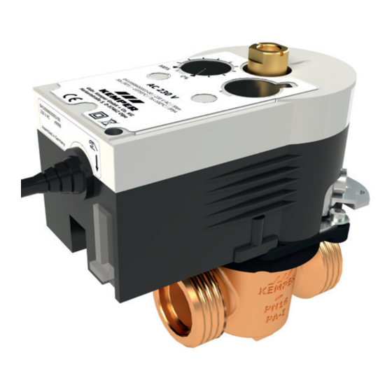
24 V AC/DC-Ausführung - Figur 686 00
230 V AC-Ausführung - Figur 686 04
EN Installation and operating instructions
quarter turn stop valve with servo drive
24 V AC/DC-version - Figure 686 00
230 V AC-version - Figure 686 04
!
2
12
Advertisement
Chapters
Table of Contents

Related Manuals for Kemper kHS 686 00


Summary of Contents for Kemper kHS 686 00
- Page 1 DE Einbau- und Bedienungsanleitung VAV Vollstrom-Absperrventil mit Stellantrieb 24 V AC/DC-Ausführung - Figur 686 00 230 V AC-Ausführung - Figur 686 04 EN Installation and operating instructions quarter turn stop valve with servo drive 24 V AC/DC-version - Figure 686 00 230 V AC-version - Figure 686 04...
-
Page 2: Table Of Contents
Tel.: +49 2761 891 800 Mail: anwendungstechnik@kemper-group. Haftung Keine Gewährleistung oder Haftung bei: - Nichtbeachten der Anleitung, - fehlerhaftem Einbau und/oder Gebrauch, - eigenständiger Modifikation am Produkt, - sonstiger, fehlerhafter Bedienung. 2 /24 – K410068600001-00 / 03.2023 – © www.kemper-group.com... - Page 3 Warnung! Kennzeichnet Ge- verwertung bzw. -beseitigung fahren, die zu Verletzungen, sind zu beachten. Produkt darf Sachschäden oder Verunreini- nicht mit normalem Haushalts- gung des Trinkwassers führen müll, sondern muss sachgemäß können. entsorgt werden. © www.kemper-group.com – 03.2023 / K410068600001-00 – 3 /24...
-
Page 4: Eigenschaften I Technische Daten
< 85 % rF (relative Feuchte) ohne Kondensation Schutzgrad IP54 Laufgeräusche < 30 dB(A) Antriebsgewicht 0,7 kg Rückmeldung Stellungsrückmeldung 0...10 V Anschlusskabel 1,2 m, 5 x 0,5 mm² 1,2 m, 3 x 0,75 mm² 4 /24 – K410068600001-00 / 03.2023 – © www.kemper-group.com... -
Page 5: Maße
Innensechskant (SW1) [mm] Werkstoffe Beschreibung Figur 686 00 l 686 04 Gehäuse Innenoberteil Rotguss und Edelstahl Spindel Rotguss Dichtelemente EPDM Kupplungsstück Rotguss Antriebsgehäuse Selbstverlöschender Kunststoff Achsadapter Stahl Flanschadapter Polyamid Durchflussbegrenzer POM Hostaform © www.kemper-group.com – 03.2023 / K410068600001-00 – 5 /24... -
Page 6: Montage
Stellantrieb ausrichten Stellantrieb aufstecken Der Stellantrieb besitzt 8 Ausrichtstufen, die Antrieb fest auf Konus aufdrücken. in 45° Schritten ausrichtbar sind. Hierzu ist die passende Stellung des Stellantriebes, je nach Platzverhältnis, zu wählen. 6 /24 – K410068600001-00 / 03.2023 – © www.kemper-group.com... - Page 7 - Ventil geschlossen kontrollieren. kant-Schlüssel SW 4 mm, Anzugsmoment - Darauf achten, dass die Stellungsanzeige- 7…9 Nm. nut quer zur Rohrachse steht. Handbetrieb Getriebeschieber Getriebeschieber = Getriebe ausgerastet. Getriebeschieber = Getriebe eingerastet. © www.kemper-group.com – 03.2023 / K410068600001-00 – 7 /24...
-
Page 8: Anschluss Als 2-Punkt-Steuerung
Elektroarbeiten dürfen nur von autorisiertem Fachpersonal ausgeführt werden! • Gehäuse darf nicht geöffnet werden! • Bei Montage im Freien: Wir empfehlen, die Geräte bei einer Montage außerhalb von Gebäuden zusätzlich vor Witterungseinflüssen zu schützen. 8 /24 – K410068600001-00 / 03.2023 – © www.kemper-group.com... -
Page 9: Richtlinien
Oberteil (A) in das Gehäuse (1) einsetzen und bis zum Anschlag positionieren. Das Oberteil wird mit einem Maulschlüssel SW 17 und einem Anzugsmoment von 20 Nm angezogen. Montage Stellantrieb wie unter Punkt 2 beschrieben. © www.kemper-group.com – 03.2023 / K410068600001-00 – 9 /24... -
Page 10: Ersatzteilliste
Ersatzteilliste Figur 686 00 l 686 04 Position Bezeichnung Bestellnr. Oberteil DN 15/20 E012068600020KP Oberteil DN 25 E012068600025KP Oberteil DN 32 E012068600032KP 10 /24 – K410068600001-00 / 03.2023 – © www.kemper-group.com... -
Page 11: Verkabelungshinweise
(230 V) Hinweis! Gemäß VDE 0815: Die Angaben von Signalübertragungsleitungen hinsichtlich des Durchmessers ist in mm aufgeführt. * Möglicher Kabel-Typ bei fester Verlegung, ohne machanische Belastung ** abgeschirmte Kabelzuleitung Stand: November 2022 © www.kemper-group.com – 03.2023 / K410068600001-00 – 11 /24... -
Page 12: Harkortstraße 5
- Failure to observe the instructions in this manual, - Incorrect installation and/or operation, - Unauthorised modification of the product, - Other improper methods of operation. 12 /24 – K410068600001-00 / 03.2023 – © www.kemper-group.com... - Page 13 Warning! Highlights risks that followed. The product must not may result in injury, material be disposed of with household damage or contamination of waste but must rather be drinking water. disposed of appropriately. © www.kemper-group.com – 03.2023 / K410068600001-00 – 13 /24...
-
Page 14: Properties I Technical Data
Protection class IP54 Operating noise < 30 dB(A) Drive weight 0,7 kg Feedback Position feedback 0...10 V Connection cable 1,2 m, 5 x 0,5 mm² 1,2 m, 3 x 0,75 mm² 14 /24 – K410068600001-00 / 03.2023 – © www.kemper-group.com... -
Page 15: Dimensions
Figure 686 00 l 686 04 Housing, interior bonnet Gunmetal and stainless steel Spindle Gunmetal Sealing elements EPDM Coupling Gunmetal Drive housing Self-extinguishing plastic Axis adapter Steel Flange adapter Polyamide Flow limiter POM Hostaform © www.kemper-group.com – 03.2023 / K410068600001-00 – 15 /24... -
Page 16: Installation
The servo drive has 8 alignment steps that Press the drive firmly onto the cone. can be al igned in 45° steps. To do that, select the appropriate servo drive position, depen- ding on the amount of space. 16 /24 – K410068600001-00 / 03.2023 – © www.kemper-group.com... - Page 17 - make sure the position indicator slot is 7….9 Nm. across to the pipe axis. Manual operation open closed Gear slider Gear slider = Disengaged gear. Gear slider = Engaged gear. © www.kemper-group.com – 03.2023 / K410068600001-00 – 17 /24...
-
Page 18: Connection As A 2-Point Controller
Work is to be carried out by authorized specia- lists only! • Opening the housing is prohibited! • When installing outdoors, KEMPER recom- mends to protect additionally the devices against weather effects. • Risk of injury by return spring. 18 /24 – K410068600001-00 / 03.2023 – © www.kemper-group.com... -
Page 19: Directive
Insert the bonnet (A) into the housing (1) and position at the limit stop. Tighten the bonnet with an SW 17 wrench using 20 Nm torque. Install the servo drive as described in Point 2. © www.kemper-group.com – 03.2023 / K410068600001-00 – 19 /24... -
Page 20: Spare Parts List
Spare parts list Figure 686 00 l 686 04 Position Designation Art.-No. Bonnet DN 15/20 E012068600020KP Bonnet DN 25 E012068600025KP Bonnet DN 32 E012068600032KP 20 /24 – K410068600001-00 / 03.2023 – © www.kemper-group.com... -
Page 21: Wiring Instruction
According to VDE 0815: The specification of signal transmission cables with respect to the diameter is specified in mm. * Possible cable type for fixed routing, without mechanical load ** Shielded cable lead Issue: November 2022 © www.kemper-group.com – 03.2023 / K410068600001-00 – 21 /24... - Page 22 22 /24 – K410068600001-00 / 03.2023 – © www.kemper-group.com...
- Page 23 © www.kemper-group.com – 03.2023 / K410068600001-00 – 23 /24...
- Page 24 Gebr. Kemper GmbH + Co. KG Service-Hotline +49 2761 891-800 Harkortstraße 5 www.kemper-group.com D-57462 Olpe info@kemper-group.com 24 /24 – K410068600001-00 / 03.2023 – © www.kemper-group.com...
Need help?
Do you have a question about the kHS 686 00 and is the answer not in the manual?
Questions and answers