
Related Manuals for Gema XT12


Summary of Contents for Gema XT12
- Page 1 Rev. 00 1024 607 Operating instructions and Spare parts list Horizontal axis XT12 Translation of the original operating instructions...
- Page 2 To the best of our knowledge and belief, the information contained in this publication was correct and valid on the date of publication. Gema Switzerland GmbH makes no representations or warranties with respect to the contents or use of this publication, and reserves the right to revise this publication and make changes to its content without prior notice.
-
Page 3: Table Of Contents
Dimensions ....................22 Sound pressure level ................22 Rating plate ....................23 Assembly / Connection Grounding of the axis .................... 26 Electrical connections / cable connections ............27 Start-up Preparation for start-up ..................29 Table of contents • 3 XT12... - Page 4 Safety regulations ..................59 Requirements on personnel carrying out the work ........59 Disposal regulations ................59 Materials ....................60 Disposal of operating material ................60 Disassembly of component groups ..............60 Preparation ....................60 4 • Table of contents XT12...
- Page 5 Rev. 00 12/22 Spare parts list Ordering spare parts ..................... 61 XT12 – complete ....................62 Toothed wheel....................... 63 Guide roller / counter roller ................... 64 Drive unit (complete) ..................... 65 Electrical module ....................66 Table of contents • 5...
-
Page 7: About These Instructions
General information This operating manual contains all the important information which you require for the working with the XT12. It will safely guide you through the start-up process and give you references and tips for the optimal use when working with your powder coating system. -
Page 8: Structure Of Safety Notes
Presentation of the contents Figure references in the text Figure references are used as cross references in the descriptive text. Example: "The high voltage (H) created in the gun cascade is guided through the center electrode." 8 • About these instructions XT12... -
Page 9: Safety
If this product is to be used for other purposes or other substances outside of our guidelines then Gema Switzerland GmbH should be consulted. -
Page 10: Special Safety Regulations
– Repairs may only be made by authorized Gema repair centers or by personnel correspondingly trained by Gema. Unauthorized conversions and modifications can lead to injuries and damage to the equipment. - Page 11 ► Before working with the device, organize the required documents and read the section "Safety regulations". ► Work should only be carried out in accordance with the instructions of the relevant documents. ► Always work with the complete original document. Safety • 11 XT12...
- Page 12 Rev. 00 12/22 12 • Safety XT12...
-
Page 13: Transport
Transport the unit only in a horizontal position. Transport Data concerning goods to be transported The space requirements correspond to the size of the axes of motion plus the packaging. Loading, transferring the load, unloading At least one fork lift must be available. Transport • 13 XT12... - Page 14 Rev. 00 12/22 14 • Transport XT12...
-
Page 15: Product Description
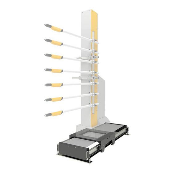
Rev. 00 12/22 Product description Intended use The XT12 axis serves exclusively to move horizontally powder applicators in automatic coating equipment. Fig. 1: Horizontal axis with ZA vertical axis Observance of the operating, service and maintenance instructions specified by the manufacturer is also part of the intended use. This... -
Page 16: Utilization
Rev. 00 12/22 Utilization The XT12 axis is used for the coating of parts with different widths. With this type of coating, the powder applicators must be moved to the position specified for each width. Typically, the horizontal axis is used in conjunction with a vertical ZA-axis. - Page 17 Rev. 00 12/22 Fig. 2: Structure Drive unit Leveling bolt Trolley Rubber buffer Power unit Z-axis Basement Levelling pad Baseboard Product description • 17 XT12...
-
Page 18: Schematic Presentation
Manually movable when the control unit is switched off – No additional space required for dismantling and service works – Low overall height with integrated leveling strips (For more information about the controlling of the axis, see the axes control unit operating manual) 18 • Product description XT12... -
Page 19: Expansion With Additional Axes Of Motion
Rev. 00 12/22 Expansion with additional axes of motion The horizontal axis can be equipped with a vertical axis to expand its functionality. Only one Z-axis can be mounted. Fig. 4: Horizontal axis with ZA vertical axis Product description • 19 XT12... -
Page 20: Cdb Position Regulator With Can Bus (Power Unit)
5: CDB position regulator with CAN BUS X1 Load connections (Mains X4 RS 232 Interface voltage, Motor) X5 CAN addresses X2 Control connection X6 not occupied X3 Motor winding temperature X7 Pulse generator connection monitoring (optional) 20 • Product description XT12... -
Page 21: Technical Data
Rev. 00 12/22 Technical Data Versions The axis is available in different travel distance lengths, in increments of 50 mm. XT12 Min. travel distance 1450 mm Max. travel distance 2000 mm Weight (min. travel distance) 197 kg Weight (max. travel distance) 213 kg 0.01 up to 0.6 m/s... -
Page 22: Dimensions
Rev. 00 12/22 Dimensions Fig. 6: Dimensions XT12 Carriage length – A 750 mm Width – B 750 mm Total length – L Travel distance + 750 mm + 60 mm Height – H 320 mm (290 + 30) Sound pressure level... -
Page 23: Rating Plate
Rev. 00 12/22 Rating plate fig. 7: Rating plate Fields with a gray background contain contract-specific data! Product description • 23 XT12... - Page 24 Rev. 00 12/22 24 • Product description XT12...
-
Page 25: Assembly / Connection
► In order to enter the inner area, the door interlocks must be released by the control unit. This release signal may only be activated by technical personnel. ► Except for normal operation, all other operating modes must be set up by an authorized technical representative. Assembly / Connection • 25 XT12... -
Page 26: Grounding Of The Axis
► Ground all metal parts of the axis according to the general, local safety regulations. ► Check regularly the grounding of the axis. At least one corresponding connection point at the axis is reserved for the potential equalization. fig. 8: Potential equalization – connection point 26 • Assembly / Connection XT12... -
Page 27: Electrical Connections / Cable Connections
24 VDC source so that in event of an interruption of power to the reciprocator the reference point remains in memory, i.e. after rewiring the power feed it is not necessary to reference the axes again. Assembly / Connection • 27 XT12... - Page 28 Rev. 00 12/22 28 • Assembly / Connection XT12...
-
Page 29: Start-Up
The stroke length of the reciprocator must be in the range of the booth opening (collision danger!). – Make sure that the automatic guns cannot collide with the work pieces (incorrectly adjusted stroke parameters on the reciprocator control unit). Start-up • 29 XT12... -
Page 30: Reference Point
► Consider the edges of the gun slot! ► It must be noted that the axes in reference travel moves up to 30 mm behind the control’s zero point! Fig. 10: Reference point and mechanical stops 30 • Start-up XT12... -
Page 31: Setting The Reference Point
30 mm behind the control’s zero point, when referencing! The positions of the rubber buffers are set by a Gema service engineer during assembly. The reference point must be referenced before each start-up (at each switching on, after an interruption of the power supply etc.)! - Page 32 Rev. 00 12/22 32 • Start-up XT12...
-
Page 33: Operation
255 programs – change the program number – directly modify the running program – acknowledge the error message – input the system parameters – etc. For further information, see the corresponding operating manual! Operation • 33 XT12... - Page 34 Rev. 00 12/22 34 • Operation XT12...
-
Page 35: Decommissioning / Storage
Requirements on personnel carrying out the work All work should be carried out only by authorized trained personnel. Storage conditions Hazard notes There is no danger to personnel or the environment if the unit is stored properly. Decommissioning / Storage • 35 XT12... -
Page 36: Type Of Storage
Unplug the ground cable Cleaning The guide and counter rollers running surface of the horizontal axis must be thoroughly cleaned. Preservation The cleaned running surfaces of the horizontal axis must be preserved with a suitable corrosion inhibitor. 36 • Decommissioning / Storage XT12... -
Page 37: Maintenance During Storage
Rev. 00 12/22 Maintenance during storage Maintenance schedule No maintenance schedule is necessary. Maintenance works During long-term storage, periodically perform a visual check for corrosion. Decommissioning / Storage • 37 XT12... - Page 38 Rev. 00 12/22 38 • Decommissioning / Storage XT12...
-
Page 39: Maintenance / Repairs
The axis was designed to operate with a minimum of maintenance. The motor gear box is self-lubricating and maintenance-free. Regular maintenance and inspection of the axis increases the working reliability and avoids damages, repair downtimes etc.! Maintenance / Repairs • 39 XT12... -
Page 40: Maintenance Plan
► The vertical axis has to be free of load! The motor gear box is self-lubricating and maintenance-free! Observe the contamination of the enclosure – strong contamination on the outside can increase the operating temperature of the drive unit! 40 • Maintenance / Repairs XT12... -
Page 41: Replacing The Drive Unit
► For safety reasons, two people should always carry out the following maintenance work! Procedure: Switch off the power supply. Loosen the fixing screws at both ends and remove the cover Loosen the fixing screws on the toothed wheel Maintenance / Repairs • 41 XT12... - Page 42 Unfasten and remove the pulse generator from the motor spindle Loosen the screws and pull out the electric module 10. Loosen the motor cable at the position regulator and pull it out through the cable gland 42 • Maintenance / Repairs XT12...
- Page 43 14. Install the new motor/gearbox unit The installation takes place exactly in the reverse order! ATTENTION Incorrectly assembled parts may cause malfunctions or defects ► Reassembly is in reverse order! ► Observe the tightening torques when assembling! Maintenance / Repairs • 43 XT12...
-
Page 44: Toothed Belt
For safety reasons, two people should always carry out the following maintenance work! Replacing the toothed belt Procedure: Switch off the power supply. Loosen the fixing screws at both ends and remove the cover Loosen the fixing screws on the toothed wheel 44 • Maintenance / Repairs XT12... - Page 45 Pass the loose end over the toothed pulley and the toothed wheel 10. Fix the free end with the second clamp plate 11. Tension the drive belt, but do not overstretch (see chapter "Tensioning the drive belt") 12. Reinstall the cover Maintenance / Repairs • 45 XT12...
-
Page 46: Tensioning The Drive Belt
Let the carriage slowly run backwards and forwards a few times, to see if the drive belt does not ride up on the toothed wheel Adjust the toothed belt tension so that the toothed belt is fully seated in both directions Tighten the lock nuts 46 • Maintenance / Repairs XT12... -
Page 47: Adjusting The Toothed Belt Tension With The Belt Tension Measuring Device
– Two parameters must be entered for each axis type A = axial distance of the toothed wheels B = length-related mass of the toothed belt Type A [mm] B [kg/m] 2072 XT12-1450 … … 2322 XT12-1700 0.327 … …... -
Page 48: Toothed Wheel
Toothed wheel Replacing the toothed wheel The following work must only be carried out by trained personnel! Procedure: Switch off the power supply Remove the fixing screws at both ends and remove the cover 48 • Maintenance / Repairs XT12... - Page 49 Loosen the fixing screws on the toothed wheel Loosen the lock nuts Loosen the tensioning screws, so that the drive belt is slack Loosen both clamping plates with the toothed belt Pull out the toothed belt Maintenance / Repairs • 49 XT12...
- Page 50 The installation takes place exactly in the reverse order! – Move the carriage slowly backwards and forwards a few times to see whether the toothed belt needs to be retightened (see chapter “Tensioning the toothed belt”). 50 • Maintenance / Repairs XT12...
-
Page 51: Guide Rollers / Counter Rollers
The following work must only be carried out by trained personnel! Procedure: Switch off the power supply Insert a suitable wooden or metal plate between the carriage and the guide profile Unscrew the screws and remove the holder Maintenance / Repairs • 51 XT12... - Page 52 Rev. 00 12/22 Loosen both set screws, do not remove them Unscrew the screws and remove the guide roller Replace the guide roller and/or individual components Loosen the lock nut and the grub screw 52 • Maintenance / Repairs XT12...
-
Page 53: Elastomer Coupling
Without removing the element cover, check for element wear debris or cracks in the side of the element (just underneath the element cover). If wear debris or cracks are found, the following maintenance procedure should be performed. Maintenance / Repairs • 53 XT12... -
Page 54: Replacement Of The Flexible Element
Remove the defective element and dispose of it properly Rotate one hub until the teeth of both hubs are aligned axially. Spread apart the flexible element so that it will fit over the hub teeth. 54 • Maintenance / Repairs XT12... -
Page 55: Installing The Element Cover
Slide the element cover onto the element until it is centered axially on the element. Install fixing screws (A) and tighten to the specified torque. Tightening torque = 1.0 Nm (10 lb-in) DO NOT exceed the specified tightening torque. Maintenance / Repairs • 55 XT12... -
Page 56: Maintenance Of The Position Regulator
► After switching off the power supply, wait at least 10 min. before working on the equipment, because the internal condensers need this time for discharging! ► Verify that the parts are deenergized by means of a voltmeter! 56 • Maintenance / Repairs XT12... -
Page 57: Fault Clearance
Rollers tightened too Adjust the counter during operation strong rollers without clearance, ensure the correct tightening torque Squeaking noise Toothed belt rides up Check the toothed during operation on the flanged wheel belt, tension correctly, if necessary Fault clearance • 57 XT12... - Page 58 Corrective action The carriage runs Pulse generator Replace the pulse into the travel limit or defective generator into the stop and Control unit defective Repair or replace stands still Travel limit Set correctly incorrectly set 58 • Fault clearance XT12...
-
Page 59: Disposal
Requirements on personnel carrying out the work The disposal of the product is to be carried out by the owner or operator. When disposing of components that are not manufactured by Gema, the instructions in the respective third-party manufacturer’s documentation must be observed. -
Page 60: Materials
Disconnect the mains supply, supply cables and additional units. Remove all product covers. Drain all existing lubricant supplies and dispose of accordingly. The product is now prepared for disassembly. The instructions in the third-party manufacturer’s documentation must be followed! 60 • Disposal XT12... -
Page 61: Spare Parts List
When using the spare parts from other manufacturers the explosion protection is no longer guaranteed. If any damage is caused by this use all warrantee claims become invalid! ► Only original Gema spare parts should be used! Spare parts list • 61 XT12... -
Page 62: Xt12 - Complete
Rev. 00 12/22 XT12 – complete Drive unit – complete, see also "Drive unit (complete)" Toothed belt – see table below 1019 225*# Toothed wheel, see "Toothed wheel" Counter roller, see "Counter roller" Guide roller, see "Guide roller / Counter roller"... -
Page 63: Toothed Wheel
Rev. 00 12/22 Toothed wheel Toothed wheel 1020 717 Toothed belt (not shown) – See also "XT12 – complete" on page 62. 1019 225#* Snap ring – I-52 209 864 Toothed drive wheel spindle 1020 840 Snap ring – A-25... -
Page 64: Guide Roller / Counter Roller
Snap ring – A-15 1015 740 Bearing bolt 1025 055 Washer – Ø 8.4/20x2 mm 215 880 Screw – M6x16 mm 244 503 # Wearing part Fig. 17: Guide roller Fig. 18: Counter roller 64 • Spare parts list XT12... -
Page 65: Drive Unit (Complete)
Clamping set – Ø 30/55x2 mm 1022 546 Toothed drive belt wheel 1022 543 Drive shaft 1023 710 Pedestal bearing – Ø 30 mm 244 708 # Wear part Fig. 19: Drive unit (complete) Spare parts list • 65 XT12... -
Page 66: Electrical Module
Signal cable CAN bus – 20 m (not shown) – for installations with 5 and more axes 10.1 1010 408 CAN bus terminal plug (not shown) 387 606 Protection cap (not shown) 265 446 * Please indicate length Fig. 20: Electrical module 66 • Spare parts list XT12... - Page 67 Start-up ............29 Electrical module ..........66 Storage ............35 Fault clearance ..........57 Technical Data ..........21 Figure references in the text ......8 Transport ............13 Maintenance ............. 39 Versions ............21 Spare parts list • 67 XT12...
- Page 68 Rev. 00...
Need help?
Do you have a question about the XT12 and is the answer not in the manual?
Questions and answers