Table of Contents
Advertisement
Quick Links
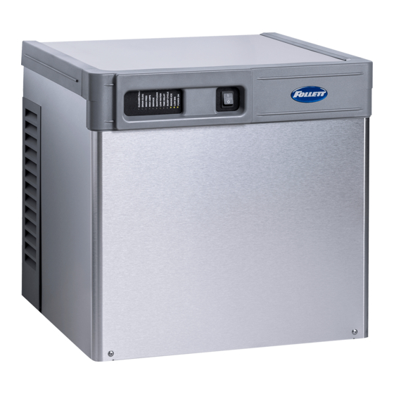
HCD1010R/N, HCD1410R/N, HMF1010R/N, HMF1410R/N
Horizon Elite™ Ice Machines (Remote Condensing)
Order parts online
www.follettice.com
Following installation, please forward this manual
HCD1010R/N, HMF1010R/N, HCD1410R/N, HMF1410R/N
to the appropriate operations person.
801 Church Lane • Easton, PA 18040, USA
Toll free (877) 612-5086 • +1 (610) 252-7301
www.follettice.com
Operation and Service Manual
Before L60418
01096122R07
1
Advertisement
Table of Contents

Related Manuals for Follett Horizon Elite HMD1010R/N


Summary of Contents for Follett Horizon Elite HMD1010R/N
- Page 1 HCD1010R/N, HCD1410R/N, HMF1010R/N, HMF1410R/N Horizon Elite™ Ice Machines (Remote Condensing) Order parts online Operation and Service Manual www.follettice.com Before L60418 Following installation, please forward this manual to the appropriate operations person. 801 Church Lane • Easton, PA 18040, USA Toll free (877) 612-5086 • +1 (610) 252-7301 01096122R07 HCD1010R/N, HMF1010R/N, HCD1410R/N, HMF1410R/N www.follettice.com...
- Page 2 HCD1010R/N, HMF1010R/N, HCD1410R/N, HMF1410R/N...
-
Page 3: Table Of Contents
Welcome to Follett........ -
Page 4: Welcome To Follett
Before you begin After uncrating and removing all packing material, inspect the equipment for concealed shipping damage. If damage is found, notify the shipper immediately and contact Follett LLC so that we can help in the filing of a claim, if necessary. -
Page 5: Specifications
§ 3/8" OD push-in water inlet (connection inside machine) - 3/8" OD tubing required. § Water shut-off recommended within 10 feet (3 m). § Follett recommends installation of Follett water filter system (part# 00130286) in ice machine inlet water line. Flush drain plumbing §... -
Page 6: Refrigeration
Water pressure 70 psi max. (483 kPa) 10 psi min. (69 kPa) Condenser unit Air temperature 120 F/49 C max. –20F/–29C min. Refrigeration § 3/8" liquid line § 5/8" suction line Rack system installations require a capacity of 10,000 BTU/hr for 1010 machines and 13,000 BTU/hr for Note: 1410 machines at 0 F (–18 C) evaporator temperature. -
Page 7: Dimensions And Clearances
Dimensions and clearances § Entire front of ice machine must be clear of obstructions/connections to allow removal. § 1" (26mm) clearance above ice machine for service. § 1" (26mm) minimum clearance on sides. § The intake and exhaust air grilles must provide at least 250 sq in (1615 sq cm) of open area. §... - Page 8 Condensing unit 26.08" (662 mm) 25.5" 36.25" (921 mm) (648 mm) HCD1010R/N, HMF1010R/N, HCD1410R/N, HMF1410R/N...
-
Page 9: Operation
Cleaning of the condenser can usually be performed by facility personnel. Cleaning of the icemaker system, in most cases, should be performed by your facility’s maintenance staff or a Follett authorized service agent. Regardless of who performs the cleaning, it is the operator’s responsibility to see that this cleaning is performed according to the schedule below. - Page 10 Fig. 2 2. Follow the directions on the SafeCLEAN Plus packaging to mix 1 gal. (3.8 L) of Follett SafeCLEAN Plus solution. Use 100 F (38 C) water. 3. Using a 1 quart (1L) container, slowly fill cleaning cup until CLEANER FULL light comes on. Do not overfill.
- Page 11 Fig. 5 7. Disconnect coupling as shown. Fig. 6 8. Using disposable food service grade gloves, insert dry Sani-Sponge. 9. Insert Sani-Sponge soaked in SafeClean Plus (from Step 4). 10. Push both Sani-Sponges down ice transport tube with supplied pusher tube. Fig.
- Page 12 Fig. 8 12. Reconnect coupling. Press power switch ON. Ice pushes Sani-Sponges through ice transport tube. Fig. 9 13. Place a sanitary (2 gal. or larger) container in bin or dispenser to collect Sani-Sponges and ice for 10 minutes. 14. Collect 5.5 lbs (3 kg) of ice from unit. Discard ice and Sani-Sponges.
-
Page 13: Service
The Horizon ice machine overview The Follett Horizon ice machine uses a horizontal, cylindrical evaporator to freeze water on its inner surface. The refrigeration cycle is continuous; there is no batch cycle. The evaporator is flooded with water and the level is controlled by sensors in a reservoir. - Page 14 Water system The water level in the evaporator is controlled by a feed solenoid and level detecting sensors. Referencing the diagram below, water sensing probes extend down into the reservoir at the end of the evaporator assembly. The system works via electrical conductivity as follows: The probe labeled B is the common.
-
Page 15: Bin Full" Detection System
“Bin full” detection system The Follett Horizon ice machine incorporates a unique “bin full” detection system that consists of the shuttle and actuator. The shuttle incorporates a flag and switch. Referencing the figure below, the normal running position of the flag is down, and the switch is closed. When the bin fills to the top and ice can no longer move through the tube, the machine will force the shuttle flag up, opening the switch and shutting the machine off. -
Page 16: Electrical System
Electrical system ATTENTION! To prevent circuit breaker/Hi-amp overload, wait 5 minutes before restarting this unit. This allows the compressor to equalize and the evaporator to thaw. Normal control board operation The PC board indicator lights provide all the information necessary to determine the machine's status. Green indicator lights generally represent “go”... - Page 17 Error faults: The Horizon PC board monitors various operating parameters including high pressure, auger gearmotor amperage limits, clogged drain, and low water alarm conditions. There are three types of errors namely “soft” (time delay) "hard" (reset), and “run” . § Soft errors will automatically reset after the 1 hour time delay or can be reset by cycling power. §...
- Page 18 Wiring diagram, evaporator unit Gearmotor data Resistance of windings 115 vac gearmotor (Bison): Gearmotor current 2.8A @ 115 V Gearmotor torque-out (high amp) trip point: 5.6A White to Black: 3Ω White to Red: –3Ω Red to Black: 6Ω HCD1010R/N, HMF1010R/N, HCD1410R/N, HMF1410R/N...
- Page 19 Single-phase condensing unit wiring diagram FAN 1 FAN 2 COMPRESSOR CONTACTOR COIL see note A RECEIVER TERMINAL HEATER BOARD HEATER THERMOSTAT POWER SUPPLY 230-60-1 POTENTIAL RELAY see note B COMPRESSOR CONTACTOR NC AUXILIARY SWITCH CRANK CASE HEATER COMPRESSOR CONTACTOR COMPRESSOR TERMINAL BLACK START...
- Page 20 3-phase condensing unit wiring diagram FAN 1 FAN 2 TO "Y-OUT" TO "230 VAC" AT PHASE AT PHASE MONITOR MONITOR COMPRESSOR D.T. TO "C" CONTACTOR AT PHASE COIL MONITOR see note A RECEIVER TERMINAL TERMINAL HEATER BOARD BOARD HEATER THERMOSTAT POWER SUPPLY 230-60-3 TO "L2"...
-
Page 21: Mechanical System
Mechanical System Fig. 10 Evaporator disassembly 1. Press CLEAN button to purge evaporator. Turn power OFF when LO WATER lights. 2. Unscrew and disconnect transport tube from louvered docking assembly. Fig. 11 3. Remove gearbox insulation.. Fig. 12 4. Disconnect gear motor wires. Fig. - Page 22 Fig. 14 6. Remove gear motor bolts (1/2" wrench). 7. Remove gear motor and wipe auger shaft clean. WIPE AUGER SHAFT Fig. 15 8. Remove main housing insulation and shuttle insulation: Fig. 16 9. Remove front feed water tube from push-in fitting, shuttle drain tube, and shuttle switch.
- Page 23 Fig. 17 10. Remove 3 screws (with 3/16" allen wrench) then remove auger and main housing together. Note: Auger is sharp - wear protective gloves.: Fig. 18 11. Rotate auger to align opening in auger flange with stream divider. 12. Pull out auger.: Fig.
-
Page 24: Evaporator Reassembly
Evaporator reassembly Fig. 20 14. Install ceramic mating ring and shaft seal. Caution: Do not touch the sealed surface of either part. Oil from bare skin will cause premature seal failure. 15. Use liquid hand soap on the rubber part of the ceramic seal when installing in main housing. - Page 25 Fig. 23 22. Install shuttle switch. § Align holes with pins (Fig. 23.1) and depress switch button (Fig. 23.2) to clear shuttle tab. Fig. 24 23. Install shuttle drain tube and front feed water tube (Fig. 24). Fig. 25 24. Install main housing insulation and shuttle insulation: 25.
- Page 26 Fig. 26 26. Slide gear motor onto auger and install gear motor bolts (9/16" wrench). Fig. 27 27. Connect gear motor wires. Fig. 28 28. Pry auger forward and rotate auger using 1/2" wrench to align keyways. 29. Insert key fully. Fig.
- Page 27 Fig. 30 31. Rotate retainer fork to align screw holes. 32. Install screws to secure retainer fork. Fig. 31 33. Install gearbox insulation. Fig. 32 34. Connect transport tube to louvered docking assembly. HCD1010R/N, HMF1010R/N, HCD1410R/N, HMF1410R/N...
- Page 28 Reservoir/rear bushing disassembly Fig. 33 1. Press CLEAN button to purge evaporator. Turn power OFF when LO WATER lights. Note: In many applications, removing the gearmotor, main housing, and auger will allow for the ice machine to be pulled out further for better access to rear components.
-
Page 29: Refrigeration System
Refrigeration system Condenser unit operation The condensing unit is weatherproof and equipped to operate in ambient temperatures from –20 F to 120 F (–29 C to 48.9 C). The condensing unit is controlled by a low pressure control, which works in concert with a refrigerant solenoid valve on the evaporator module. - Page 30 Refrigeration system diagram CONDENSER UNIT FILTER SUCTION LOW SIDE ACCUMULATOR SERVICE VALVE W/ SERVICE PORT HIGH SIDE HIGH SIDE SERVICE VALVE SERVICE VALVE COMPRESSOR W/ SERVICE PORT W/ SERVICE PORT RECEIVER FILTER-DRIER SIGHT GLASS HIGH SIDE SERVICE VALVE HIGH PRESSURE SWITCH W/ SERVICE PORT CHECK VALVE LOW SIDE...
- Page 31 Note: Condensing unit shipped with 0.5 lb of R404A charge. Refrigerant replacement requirements 1. Non-contaminated refrigerant removed from any Follett refrigeration system can be recycled and returned to the same system after completing repairs. Recycled refrigerant must be stored in a clean, approved storage container.
-
Page 32: Troubleshooting
Troubleshooting Please see “Service” section for a description of each function. Ice machine disposition Possible causes Corrective action Legend: ON or OFF FLASHING Ice machine is in running 1. Defective compressor. 1. Replace compressor. condition but not making ice. 2. Defective start relay. 2. - Page 33 Ice machine disposition Possible causes Corrective action Legend: ON or OFF FLASHING 6. Ice machine is making ice. 1. Failed water sensors. Processor 1. Clean or replace water probe Excessive water in bin or assumes there is no water when assembly.
-
Page 34: Replacement Parts
Replacement parts Evaporator assembly (Before Serial Number K81440) HCD1010R/N, HMF1010R/N, HCD1410R/N, HMF1410R/N... - Page 35 Reference # Description Part # Tube, ice transport, insulated 01118181 Shuttle assembly 01118132 Shuttle assembly, IMDV 01118140 Switch, shuttle 01006261 Compression nozzle 01278654 O-ring, shuttle 01111848 Screw, reservoir (3 required) 206395 Auger hardware (includes screws, key, retainer) 01175587 01164938 Bolt, gearmotor mounting (2) (remote condensing units), includes washers 01125012 Cartridge assembly, shuttle spring 01118033...
- Page 36 Replacement parts Evaporator assembly (After Serial Number K81439) HCD1010R/N, HMF1010R/N, HCD1410R/N, HMF1410R/N...
- Page 37 Reference # Description Part # Tube, ice transport, insulated 01118181 Shuttle assembly 01118132 Shuttle assembly, IMDV 01118140 Switch, shuttle 01006261 Compression nozzle 01058072 O-ring, shuttle 01111848 Screw, reservoir (3 required) 206395 Auger hardware (includes screws, key, retainer) 01118611 01164938 Bolt, gearmotor mounting (2) (self-contained units), includes washers 01118629 Cartridge assembly, shuttle spring 01118033...
-
Page 38: Low-Side Assembly
Low-side assembly HCD1010R/N, HMF1010R/N, HCD1410R/N, HMF1410R/N... - Page 39 Reference # Description Part # Tubing, liquid line (includes insulation) 01071448 Tubing, suction line (includes insulation) 01121391 Sight glass 01165570 Electrical box support 01121292 Valve, expansion, thermal (includes TXV insulation) 01118942 Insulation, TXV (bulb and body) 502830 Valve, shut-off, liquid line 00107060 Kit, liquid line solenoid (Includes filter drier) 01191493...
-
Page 40: Electrical Box
Electrical box HCD1010R/N, HMF1010R/N, HCD1410R/N, HMF1410R/N... - Page 41 Reference # Description Part # Cover, electrical box, air/water-cooled 01118975 Board, control, 120 V (includes stand-offs) 01117829 Stand-offs (set of 8) 00130906 Switch, TDS 01165695 Switch, evaporator clean 01165703 Switch, ice machine power 01165711 Cord, power, 120 V 01111491 Cable, IMDV 01071596 HCD1010R/N, HMF1010R/N, HCD1410R/N, HMF1410R/N...
-
Page 42: Integration Kit - Top-Mount And Ride Remote Ice Delivery
Integration kit – top-mount and RIDE remote ice delivery Top mount configuration RIDE model configuration HCD1010R/N, HMF1010R/N, HCD1410R/N, HMF1410R/N... - Page 43 Reference # Description Part # Shuttle actuator 00171322 Clamp 500377 Actuator elbow (includes 00167122 and 209100) 00171264 Screws 209100 Gasket 00167122 Actuator body 00171272 Gasket, coupling 00126532 Ring, locking (includes 00126532) 00171371 Ice transport tube, 10' (3m) 00171280 Ice transport tube, 20' (6m) 00171298 Insulation, transport tube 501176...
-
Page 44: Skins Assembly
Skins assembly HCD1010R/N, HMF1010R/N, HCD1410R/N, HMF1410R/N... - Page 45 Reference # Description Part # Cover, front 01121417 Coupling (includes O-ring) 00171207 O-ring 00144675 Bulkhead fitting 00171215 00145342 Hose clamp 500377 Plate, strain relief 00192070 Louvered docking assembly, 1010 (includes strain relief plate, bulkhead 01121425 (1010 only) fitting) Louvered docking station, 1410 (includes strain relief plate, bulkhead 01121433 (1410 only) fitting) Screw...
-
Page 46: 1010 Single-Phase Condensing Unit
1010 Single-phase condensing unit Top View Side View 19 12 Reference # Description Part # Shroud 01018290 Condenser 01018324 Head pressure control valve 01021401 Condenser fan motor 01018266 Condenser fan guard 00123067 Receiver 01122514 Filter drier, liquid 01122522 Compressor (includes start and run capacitors, relay, suction and liquid drier) 01122605 Shut-off valve, suction line 00107078... -
Page 47: 1410 Single-Phase Condensing Unit
1410 Single-phase condensing unit Top View Side View 19 12 Reference # Description Part # Shroud 01018290 Condenser 01018324 Head pressure control valve 01021401 Condenser fan motor 01018266 Condenser fan guard 00123067 Receiver 01122514 Filter drier, liquid 01122522 Compressor (includes start and run capacitors, relay, suction and liquid drier) 01122639 Shut-off valve, suction line 00107078... -
Page 48: 1010 3-Phase Condensing Unit
1010 3-phase condensing unit Top View Side View Reference # Description Part # Shroud 01018290 Condenser 01018324 Head pressure control valve 01021401 Condenser fan motor 01018266 Condenser fan guard 00123067 Receiver 01122514 Filter drier, liquid 01122522 Compressor (includes crankcase heater, check vale and filter driers) 01122621 Shut-off valve, suction line 00107078... -
Page 49: 1410 3-Phase Condensing Unit
1410 3-phase condensing unit Top View Side View Reference # Description Part # Shroud 01018290 Condenser 01018324 Head pressure control valve 01021401 Condenser fan motor 01018266 Condenser fan guard 00123067 Receiver 01122514 Filter drier, liquid 01122522 Compressor (filter driers) 01122647 Shut-off valve, suction line 00107078 Shut-off valve, liquid line... - Page 50 HCD1010R/N, HMF1010R/N, HCD1410R/N, HMF1410R/N...
- Page 51 HCD1010R/N, HMF1010R/N, HCD1410R/N, HMF1410R/N...
- Page 52 Le rogamos consulte el manual de instalación y de instrucciones adjunto, ya que es muy importante que la instalación se realice según las especificaciones de fábrica para que el equipo funcione a su máxima eficiencia. Follett LLC no se hace responsable de los daños indirectos, costos, gastos por conexión y desconexión o pérdidas por causa de defecto de la máquina.
- Page 53 Registrazione della garanzia e valutazione dell’attrezzatura Grazie per aver acquistato un dispositivo Follett®. Ci auguriamo che il nostro prodotto soddisfi o superi le Sue aspettative, in quanto il nostro obiettivo è quello di offrire prodotti e servizi di alta qualità che soddisfino pienamente le vostre esigenze! La preghiamo di leggere attentamente il manuale per l’installazione e per l’uso allegato.
- Page 54 Garantiregistrering och utvärdering av utrustning Tack för att du köpt utrustning från Follett ® . Vi hoppas att du ska tycka att den uppfyller eller överträffar dina förväntningar, då vårt mål är att leverera produkter och tjänster av högt värde som gör dig helt nöjd! Studera medföljande installations- och bruksanvisning.
Need help?
Do you have a question about the Horizon Elite HMD1010R/N and is the answer not in the manual?
Questions and answers