Table of Contents
Advertisement
Quick Links
Contents
1.
Specification ......................... 2
2.
Controls .................................. 4
3.
Measuring mode menu ..... 7
3.1 Pressure measurement ..... 7
3.2 Flow Speed ........................... 8
................................................... 9
3.4 Humidity measurement ... 10
4.
Stresstest (TRGI) ............... 11
5.
Maintest (TRGI) .................. 13
6.
Leakage rate ....................... 14
7.
Mean Value menu ............. 16
8.
Setup menu ......................... 17
8.1 Basic setting ....................... 17
8.2 Logo entry ........................... 20
9.
Logger/IR fuction menu .. 22
10. Changing the battery ....... 24
11. Set for the leak test .......... 27
14. Quick start guide ....................
central section ................... 32
Advertisement
Table of Contents

Related Manuals for Wohler DC 2000


Summary of Contents for Wohler DC 2000
-
Page 1: Table Of Contents
Pressure Computer DC 2000 Contents Specification ......2 Controls ........4 Measuring mode menu ..7 3.1 Pressure measurement ..7 3.2 Flow Speed ......8 3.3 Temperature measurement ............ 9 3.4 Humidity measurement ... 10 Stresstest (TRGI) ....11 Maintest (TRGI) .... -
Page 2: Pressure Computer Dc 2000
Specification Manual Instructions Specification Pressure computer DC 2000 is a high-precision, multifunctional multimeter for registering differential pressure, flow rates, temperature and humidity (optional). The extremely large dynamic range of the device, even in the basic version, means that in addition to highly-sensitive measurements of the smallest pressure levels in the Pascal... - Page 3 Specification Manual Instructions 1.1 Measurement values Differential pressure measurement Differential pressure measurement Differential pressure measurement Differential pressure measurement Differential pressure measurement (temperature-compensated Piezo sensor) Measuring range: +/-2 bar 1 Pa resolution in the range –125,00 hPa to +125,00 hPa, otherwise 10 Pa Accuracy: <3% o.rd., in the range <+-200 Pa.
-
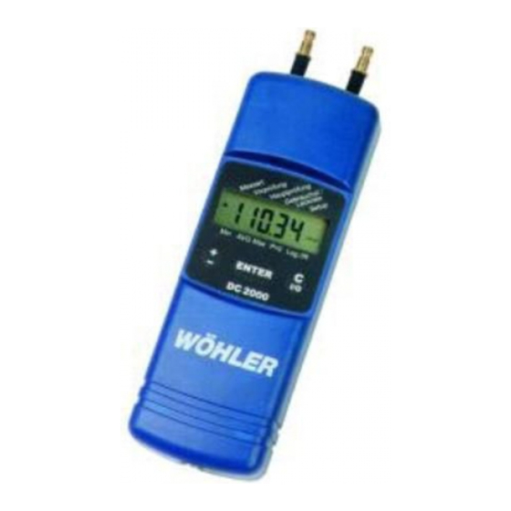
Page 4: Controls
Dimensions: 54 x 165 x 52 mm 2.Controls and ports Figure 1 below shows the display and controls of the DC 2000. The display always shows the trend on the left ( ), the numeric value in the center and the associated unit of measurement on the right. - Page 5 Test” (see 1) to the right to “Main Test”. You can return to the “Preliminary Test” position by double-clicking (see 2: “ “ indicates an active reverse function) and then clicking once. Unit of active measurement Figure 1: DC 2000 display and controls The “ENTER” key “ENTER” key “ENTER” key “ENTER” key “ENTER”...
- Page 6 Figure 2:Connections and ports of pressure computer DC 2000 A hose with an internal diameter of 5-6 mm or, depending on the version of the DC 2000, a quick-action connection type DN 2.7 can be attached. Silicon hoses should not be used in higher pressure ranges as this material can be subject to perforations at an overpressure of only 1 bar, leading to leaks.
-
Page 7: Measuring Mode Menu
Measuring Mode menu Manual Instructions 3.The Measuring Mode menu After power-on, the device carries out a self-test. After this the time and date are dis- played. If the device’s logger function was activated, then the text “Log” appears instead of the self-test, followed by current measurement and storage values, before the device switches off again. -
Page 8: Flow Speed
If the temperature T of the air stream to be measured deviates from the room temperature of the DC 2000, the combustion air temperature sensor can be inserted in the stream in parallel with the Prandtl pipe via the 2 m cable connection. In this way, the air density p is automatically tracked in accordance with the temperature T measured according to GI. -
Page 9: Temperature Measurement
Measuring Mode Menu Manual Instructions total air pressure stat. pressure temperature sensor (optimal) Figure 4:Prandtl pipe, order no. 9487 with combustion air temperature sensor A97 order no. 9611 for automatic correction of density 3.3 Temperature measurement In order to activate temperature measurement, the “+” key is pressed in the Measuring Measuring Measuring Measuring... -
Page 10: Humidity Measurement
Measuring Mode Menu Manual Instructions sation for the pressure signal and optional moisture sensor signal. Thus, when room temperature and moisture are being continuously measured, the hous- ing should not be exposed to any direct sunlight or heat. 3.4 Humidity measurement (optional) To activate humidity measurement, press the “+”... -
Page 11: Stresstest (Trgi)
DC 2000. First the line should be closed and a suitable test stopper should be inserted. The DC 2000 should be switched on before it is connected to the test stopper. After taring, the V V V V V orprüfung orprüfung... - Page 12 Preliminary Test Manual Instructions The DC 2000 prompts you to increase pressure until you reach test pressure (e.g. 1 bar). If the overpressure connector has been mistakenly confused with the underpressure connector, then the word “exchange” appears on the display. The stabilization phase starts when the pressure reaches the preset test pressure (default setting: wand period =2 minutes).
- Page 13 100 mbar can also be executed and documented very easily with the DC 2000. First the line should be closed and a suitable test stopper should be inserted. The DC 2000 should be switched on before it is connected to the test stopper. After taring, the Maintest Maintest Maintest Maintest menu item is activated with the “±“...
- Page 14 Manual Instructions Measuring leakage rates This result is stored in the DC 2000 and can also be printed out subsequently under the menu item Log./IR Log./IR Log./IR Log./IR and Print Print Print Print or transferred to the PC. Log./IR Print The protocol is only deleted after the logger has started or after another test according to TRGI.
-
Page 15: Maintest (Trgi)
Running text: “Print,..“ activate printout with the “ENTER” key “±“ key Difference:9.9 hPa “±“ key etc..This result is stored in the DC 2000 and can also be printed out subsequently under the Log./IR Log./IR Print Print menu item Log./IR Log./IR... -
Page 16: Min., Max
7.Min-, Max and AGV values Manual Instructions The leakage rate is calculated automatically according to the following formulae (3) & (4) and thereby corresponds to the procedure set out in DVGW-TRGI worksheet G 624: • • Bmax • f • Start •... - Page 17 Setupmenu Manual Instructions AVG new =ALPHA • current measured value ++(1-ALPHA)• AVG old AVG new Mean value at current time AVG old Mean value one second previously ALPHA Weight factor for current measured value (0.01..0.99) Setup menu for basic settings and logo entry The setup menu is used to set the basic configuration.
-
Page 18: Setupmenu
Setupmenu Manual Instructions Gas type Natural gas City gas Propane Butane Hydrogen Table 1:Relative viscosity of various gases as per Gl.(3) according to DVGW-TRGI 3.Setup ->absolute air pressure Here the current local air pressure (QFE) p is entered in hPa for Gl.(2) for calculating speed and for Gl.(4) for determining the leakage rate. - Page 19 Setup ->Logo The logo text for printer output can be entered here; this is explained in the next section, 8.2.(default “WÖHLER MGKG, DC 2000”) Setup ->Default This function restores the setup status on delivery. The logo text is overwritten with the original Wöhler logo.
-
Page 20: Logo Entry
Manual Instructions 8.2 Logo entry The following tables 2 & 3 simplify logo entry on the DC 2000. First you write the required text in the upper table 3 (preferably with a pencil). The first two lines have 12 characters and will be printed in bold face. The following lines 4 to 6 can contain a maximum of 24 characters and these are printed as normal.. - Page 21 Setupmenu Manual Instructions...
- Page 22 Log./IR ->IrDA to the PC. The contents of the DC 2000’s memory are transferred to the PC using infra-red technol- ogy via the IR interface (order no. 9631). The data can be received there using the Win- dows Hyperterminal, for example, and edited in Excel. An Excel program, DC2000.XLS, can also be downloaded as “freeware“...
- Page 23 Logger/IR Function Manual Instructions First the Windows terminal program or Hyperterminal should be switched to “Receive Text File” on the PC with the settings shown in figure 9 (9600, 8, 0, 1, Xon/Xoff). The required file name must already exist (see figure 8). Figure 9 below shows how the inter- face parameters should be set.
- Page 24 Logger/IR Function Manual Instructions Figure 9: sample setting for the “Hyperterminal Program“ for receiving data, in this case via COM1.
- Page 25 Logger/IR Function Manual Instructions Logger/IR function Table 4:Example of a receive sequence: Channel number + measured value 303025.01.0213:38:19 Start: Channel no. 3030 = Date, time 3031 107.35 Channel no. 3031+Druckmesswert in 3038 22.0 Channel no. 3038 +Internal temperature 3040 40 Channel no.
- Page 26 Replacing the batteries Manual Instructions If you press any key while using the logger, the DC 2000 simply displays the current measurement values after the word “Log“, followed by the remaining available memory. Te cursor is blocked for other commands. Logger mode is ended by switching off the device with the CI/O key (3 seconds).
-
Page 27: Set For The Leak Test
Leak test set Manual Instructions 11. Set for the leak test of gas lines Leak test with one-pipe meter-cap... - Page 28 Leak test set Manual Instructions Leak test with conical stopper at the open gasline or two-pipes meter...
- Page 29 Leak test set Manual Instructions Leak test with high-pressure stage stopper...
- Page 30 Leak test set Manual Instructions Measuring of the differential pressure at the pressure reducer The article 7232 is necessary for die measuring of the differential pressure at the pressure reducer!
-
Page 31: Accessories + Guarantee
Order no. 7203 12.2 Guarantee Every WÖHLER DC 2000 pressure computer is subjected to a rigorous functional check and only leaves our factory after comprehensive quality control. The final inspection is recorded in detail in a test report and is stored by us. If the device is used correctly, the guarantee period is 24 months from the date of sale. -
Page 32: Declaration Of Conformity
Product name: Pressure computer Model number: Wöhler DC 2000 Complies with the main safety requirements, which are set down in the guidelines of the Council for the Harmonization of Legal Regulations of the Member States in relation to electromagnetic compatibility (89/336/EWG and 93/97/EWG).
Need help?
Do you have a question about the DC 2000 and is the answer not in the manual?
Questions and answers