
Subscribe to Our Youtube Channel
Related Manuals for Atlas Copco QES 250 Vod S3A ESF


Summary of Contents for Atlas Copco QES 250 Vod S3A ESF
- Page 1 Instruction Manual Instruction Manual for Industrial Generators English QES 250 Vod S3A ESF TAD 754 GE QES 325 Vod S3A ESF TAD 1351 GE QES 400 Vod S3A ESF TAD 1355 GE QES 500 Vod S3A ESF TAD 1651 GE...
- Page 3 QES 250-500 Vod S3A ESF Instruction Manual for Industrial Generators Instruction manual .................. 5 Circuit diagrams .................. 133 Original instructions Printed matter N° 2960 1530 00 ATLAS COPCO - PORTABLE ENERGY DIVISION 10/2018 www.atlascopco.com...
- Page 4 While every effort has been made to ensure that the information in this manual is correct, Atlas Copco does not assume responsibility for possible errors. Copyright 2018, Grupos Electrógenos Europa S.A., Zaragoza, Spain. Any unauthorized use or copying of the contents or any part thereof is prohibited. This applies in particular to trademarks, model denominations, part numbers and drawings.
-
Page 5: Table Of Contents
Please read the following instructions carefully before starting to use your machine. While every effort has been made to ensure that the information in this manual is correct, Atlas Copco does not assume responsibility for possible errors. Atlas Copco reserves the right to make changes without prior notice. - Page 6 Available options...... 98 4.3.1 Accessing the main front panel 5.4.4 Adjustments and service editor ..........43 procedures ........75 Control cubicle versatility ....98 4.3.2 Editing a parameter ......43 Preventing low loads .......79 Circuit diagrams .......98 ECU configuration......44 5.5.1 General..........79 Overview of the electrical options .99 4.4.1 Normal ECU operation ....44 5.5.2...
- Page 7 9.4.14 DSE2130™ input expansion 10.6 Conversion list of SI units into British module ..........103 units..........131 9.4.15 DSE2520™ remote display (Only 10.7 Data plate........131 DSE7320MKII™ (Qc2212)) .....103 9.4.16 DSE855™ communications device (Only DSE7320MKII™ (Qc2212)) ...104 9.4.17 Power Transfer Box (PTB) .....104 Overview of the mechanical options ..........105 Description of the mechanical...
-
Page 8: Safety Precautions For Industrial Generator Sets
The policy of Atlas Copco is to provide the users of their Atlas Copco equipment. It is the responsibility of unsafe operating conditions. Take necessary steps to equipment with safe, reliable and efficient products. -
Page 9: General Safety Precautions
General safety precautions The manufacturer does not accept any liability for any Pressure and temperature gauges shall be checked damage arising from the use of non-original parts and for regularly with regard to their accuracy. They shall The owner is responsible for maintaining the unit in modifications, additions or conversions made without be replaced whenever outside acceptable tolerances. -
Page 10: Safety During Transport And Installation
Never refill fuel while the unit is running, unless frequency, voltage, current and power factor lifting beam shall be applied between hoist and otherwise stated in the Atlas Copco Instruction comply with the ratings of the generator set. load. Book (AIB). Keep fuel away from hot parts such as air outlet pipes or the engine exhaust. - Page 11 All doors shall be shut during operation so as not to - above 105 dB(A): special ear protectors that are 15 Safety shoes should be compulsory in any disturb the cooling air flow inside the bodywork adequate for this noise level and the spectral workshop and if there is a risk, however small, of and/or render the silencing less effective.
-
Page 12: Safety During Maintenance And Repair
11 Do not remove any of, or tamper with, the sound- set is provided with circuit breakers for overload Parts shall only be replaced by genuine Atlas Copco damping material. Keep the material free of dirt and protection. When a breaker has tripped, reduce the replacement parts. -
Page 13: Tool Applications Safety
Tool applications safety Battery safety precautions 16 When repair has been completed, the machine shall be barred over at least one revolution for Apply the proper tool for each job. With the knowledge When servicing batteries, always wear protecting reciprocating machines, several revolutions for of correct tool use and knowing the limitations of tools, clothing and glasses. -
Page 14: Main Parts
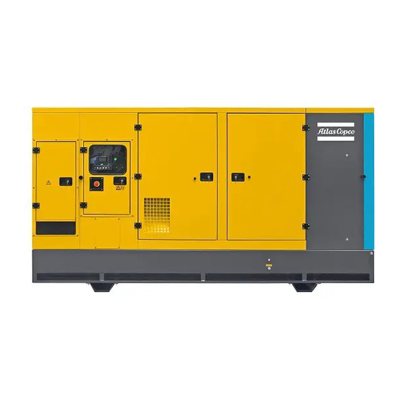
Main parts General description The QES 250-500 are generator sets, built for continuous running at sites where no electricity is available or as stand-by in cases of interruption of the mains. The QES 250-325-400-500 operates at 50 Hz, 400V - 3 phase or at 60 Hz, 480V - 3 phase. Some parts of the unit are different, depending on which version. The QES 250-500 generator sets are driven by a fluid-cooled diesel engine, manufactured by Volvo. - Page 15 Alternator Air filter Coupling Drain flexible cooling water Engine View A Filler cap cooling water Fuel filter Battery Oil filter Battery switch - 15 -...
-
Page 16: Markings
Markings Indicates the sound power level in Indicates the external fuel tank. Markings provide instructions and information. They accordance with Directive 2000/14/ EC (expressed in dB (A)). also warn of hazards. For convenience and safety, keep all markings in legible condition, replacing them Indicates that the alternator should not when damaged or missing. -
Page 17: Mechanical Features
Mechanical features 2.3.4 Bodywork 2.3.9 Fuel filter with water separator The alternator, the engine, the cooling system, etc. of The mechanical features described in this chapter are the QES generator set are enclosed in a sound- An additional fuel filter with water separator standard provided on this generator set. -
Page 18: Electrical Features
Electrical features A1 ..DSE7320MKII™ (Qc2212)/ DSE8610MKII™ (Qc3012)/DSE8620™ The electrical features described in this chapter are (Qc3111) display standard provided on this generator set. For all other electrical features, see “Overview of the electrical FS1..Earth leakage relay (Option) options” on page 99. Detects and indicates an earth fault current and activates the main circuit breaker Q600. -
Page 19: Dse7320Mkii™ (Qc2212) Control Module Description
2.4.2 DSE7320MKII™ (Qc2212) TEST: Allows to put the control UP: Allows to scroll to the next item control module description module in Test mode. This allows an above. Increases the value of the on load test of the generator set. selected set point in the editor menu. - Page 20 2.4.2.2 DSE7320MKII™ (Qc2212) LEDs 2.4.2.3 DSE7320MKII™ (Qc2212) menu Instrument pages overview It is possible to scroll to display the different pages of information by repeatedly operating the NEXT / Status page PREVIOUS PAGE pushbuttons. DSE7320 This is the ‘home’ page, the page that is displayed Example: when no other page has been selected, and the page that is automatically displayed after a period of...
- Page 21 Mains page If no buttons are pressed upon entering an – Auxiliary Sensors (If fitted and configured) instrumentation page, the instruments will be Contains electrical values of the mains (utility) – Engine Maintenance Due (If configured) displayed automatically. supply, measured or derived from the module’s mains –...
- Page 22 CAN error messages AUTO Mode Press DOWN to view the next most recent shutdown alarm. Continuing to press DOWN cycles through the When connected to a suitable CAN engine the – Scheduled runs will operate ONLY if the module past alarms after which the display shows the most controller displays alarm status messages from the is in AUTO mode with no Shutdown or Electrical recent alarm and the cycle begins again.
-
Page 23: Dse8610Mkii™ (Qc3012) Control Module Description
2.4.3 DSE8610MKII™ (Qc3012) AUTO: Is used to put the control PREVIOUS PAGE: Go to the control module description module in Automatic mode. previous page/digit. The DSE8610MKII™ (Qc3012) control module is integrated in the control panel.The DSE8610MKII™ (Qc3012) will carry out all necessary tasks to control MUTE/LAMP TEST: Silences the NEXT PAGE: Go to the next page/ audible alarm if it is sounding and... - Page 24 2.4.3.2 DSE8610MKII™ (Qc3012) LEDs 2.4.3.3 DSE8610MKII™ (Qc3012) menu Instrument pages overview It is possible to scroll to display the different pages of information by repeatedly operating the NEXT / Status page PREVIOUS PAGE pushbuttons. This is the ‘home’ page, the page that is displayed Example: when no other page has been selected, and the page that is automatically displayed after a period of...
- Page 25 Generator page Serial port page If no buttons are pressed upon entering an instrumentation page, the instruments will be Contains electrical values generator This section is included to give information about the displayed automatically. (alternator), measured or derived from the module’s currently selected serial port and external modem (if voltage and current inputs.
-
Page 26: Dse8620™ (Qc3111) Control Module Description
2.4.4 DSE8620™ (Qc3111) control MANUAL Mode To view the event log, repeatedly press the NEXT PAGE button until the LCD screen displays the Event module description – Scheduled runs will not occur when the module is log: in MANUAL mode. The DSE8620™... - Page 27 2.4.4.2 DSE8620™ (Qc3111) LEDs TEST: Allows to put the control UP: Allows to scroll to the next item module in Test mode. This allows an above. Increases the value of the on load test of the generator set. selected set point in the editor menu. AUTO: Allows to put the control DOWN: Allows to scroll to the next module in Automatic mode.
- Page 28 2.4.4.3 DSE8620™ (Qc3111) menu Instrument pages If no buttons are pressed upon entering an overview instrumentation page, the instruments will be It is possible to scroll to display the different pages of displayed automatically. information by repeatedly operating the NEXT / Status page PREVIOUS PAGE pushbuttons.
- Page 29 Generator page Mains page Serial port page Contains electrical values generator Contains electrical values of the mains (utility) This section is included to give information about the (alternator), measured or derived from the module’s supply, measured or derived from the module’s mains currently selected serial port and external modem (if voltage and current inputs.
- Page 30 MANUAL Mode – Scheduled runs will not occur when the module is in MANUAL mode. – Activation of a Scheduled Run ‘On Load’ when the module is operating OFF LOAD in Manual mode will have no effect, the set continues to run OFF LOAD.
-
Page 31: Output Terminal Board
2.4.5 Output terminal board 2.4.6 Emergency stop button The cubicle provides a terminal board for easier Push the button to stop the generator set in case of an connection of cables. It is situated on the power panel. emergency. When the button is pressed, it must be unlocked, by turning it anti-clockwise, before the Ample space is foreseen to facilitate the connection of generator set can be restarted. -
Page 32: Overview Of Applications
Overview of applications Required material Mode Configuration Description for N generator sets This configuration is used to connect one Single generator set as stand-by power with the mains. 1 x DSE8620™ (Qc3111) Stand-by Single Parallel to The generator set will synchronize with the 1 x Genset circuit breaker Genset Mains... - Page 33 Required material Mode Configuration Description for N generator sets This configuration is used to connect several generator sets in parallel as prime power island supply. The generator set synchronize together N x DSE8610MKII™ and supply power to the load. The generator (Qc3012) Prime Power sets will share the load and the power...
-
Page 34: Installation And Connection
Installation and Installation connection 3.2.1 Indoor installation Lifting The generator set exhaust contains deadly carbon monoxide gas. Do not use the holes in the skid to lift Exhaust gases must be evacuated to the generator set. a well ventilated area where people will not be endangered. -
Page 35: Outdoor Installation
– Leave enough space for operation, inspection and maintenance (at least 1 meter at each side). Consult Atlas Copco for measures against the adverse influence of non-linear loads. – Check that the inner earthing system is in compliance with the local legislation. -
Page 36: Quality, Minimum Section And Maximum Length Of Cables
3.3.2 Quality, minimum section and 3.3.3.2 Protection The lowest acceptable wire section and the maximum length of cables corresponding maximum cable or conductor length For safety reasons, it is necessary to for multiple core cable or H07 RN-F, at rated current, provide an isolating switch or The cable connected to the terminal board of the for a voltage drop e lower than 5% and at a power... -
Page 37: Operating Instructions
Operating instructions Before starting Genset operating modes – With the generator set standing level, check the The generator set can be used in 4 operating modes: In your own interest, always strictly engine oil level and top up if necessary. The oil –... -
Page 38: Stop Mode
4.2.1 Stop mode 4.2.2 Automatic mode/Mains Failure 3. If a start request is still present at the end of the start delay timer, the fuel relay is energised and This mode of operation is used to ensure continuity of 1. Activate STOP mode by pressing the STOP/ the engine will be cranked. - Page 39 4.2.2.2 Engine running 4.2.2.3 Stopping 6. The Load will be transferred from the mains supply to the generator set. 1. Once the engine is running the Warm Up timer, if 1. The return delay timer operates to ensure that the NOTES: selected, begins, allowing the engine to stabilise starting request has been permanently removed...
-
Page 40: Automatic Mode/Remote Start In Island Mode
4.2.3 Automatic mode/Remote start 5. The engine is cranked for a pre-set time. If the 2. The generator set will first be instructed to in Island Mode engine fails to fire during this cranking attempt synchronise with the mains supply before closing then the starter motor is disengaged for the pre-set the Generator Contact/Breaker and transferring This mode of operation is used to start the set in... -
Page 41: Manual Mode
4.2.4.1 Starting sequence 4. Once the Cooling timer expires, the Fuel Solenoid 4. After the starter motor has disengaged, the Safety is de-energised, bringing the generator set to a On timer activates, allowing Oil Pressure, High When in manual mode, the set will not start stop. -
Page 42: Test Mode
4.2.5 Test mode 4.2.4.3 Manual speed control 4. After the starter motor has disengaged, the Safety On timer activates, allowing Oil Pressure, High Activate test mode by pressing the TEST pushbutton. 1. Navigate to the instruments page using the buttons Engine Temperature, Under-speed, Charge Fail An LED indicator beside the button confirms this and locate ENGINE SPEED. -
Page 43: Front Panel Configuration
Front panel configuration 4.3.2 Editing a parameter 6. Repeat this process for the other digits of the PIN number. You can press PREVIOUS PAGE if you 1. Enter the editor as described above. This configuration mode allows the operator limited need to move back to adjust one of the previous customising of the way the module operates. -
Page 44: Ecu Configuration
ECU configuration During operation When the ECU is powered down (as is normal when in STOP mode), it is not possible to read the Regularly carry out following checks: diagnostic trouble codes instrumentation. 4.4.1 Normal ECU operation – Check the display for normal readings. Additionally, it is not possible to use the engine When the DSE controller is correctly configured and manufacturers’... -
Page 45: Maintenance
– Disconnect the battery using the battery isolator switch. To cut mains voltage, switch off the 10A circuit breaker in the PTB panel supplied by Atlas Copco. If made by another manufacturer, make sure that this cut is done properly before handling the generator set. -
Page 46: Qes 250 Maintenance
2000 hours For the most important subassemblies, Atlas Copco has developed service kits that combine all wear parts. These service kits offer you the benefits of genuine parts, save on administration costs and are offered at reduced price, compared to the loose components. Refer to the parts list for more information on the contents of the service kits. - Page 47 100 hours after Every Every Every Maintenance schedule Daily Yearly start-up 500 hours 1000 hours 2000 hours Replace fan/alternator belt Clean radiator (1) Clean intercooler (1) Check for obstructions on crankcase breather filter and hoses, replace if needed Check for leaks in engine-, air-, oil-, or fuel system Analyse coolant (4) (7) Drain lube oil/condensation from intercooler Adjust engine inlet and outlet valves (2)
- Page 48 100 hours after Every Every Every Maintenance schedule Daily Yearly start-up 500 hours 1000 hours 2000 hours Check emergency stop (13) Drain condensate and water from spillage-free frame or catch basin (8) Inspect/Replace hoses and clamps Check electrical system cables for wear Check torque on critical bolt connections (12) Check electrolyte level and terminals of battery (10) Grease locks and hinges...
- Page 49 2913 0029 00: pH meter The order number of the service packs are listed in the Atlas Copco Parts list (ASL). Order service packs at (8) See section “Before starting”. your local Atlas Copco dealer. (9) Replace all rubber flexibles every 5 years.
-
Page 50: Alternator Maintenance Procedures
5.2.2 Alternator maintenance 5.2.3 Engine maintenance 5.2.3.2 Engine oil change procedures procedures The table below shows the oil change interval according to the sulphur content in the fuel. Refer to the Engine Operation Manual for a full 5.2.2.1 Measuring the alternator insulation maintenance schedule. - Page 51 3. Turn off the engine. – The pH-meter can be ordered from Atlas Copco 4. Check the oil level after a few minutes. with part number 2913 0029 00. 5. Top up with oil as necessary.
- Page 52 Flush – A refractometer can be ordered from Atlas Copco – Flush twice with clean water. Used coolant must with part number 2913 0028 00. be disposed or recycled in accordance with laws and local regulations.
-
Page 53: Adjustments And Service Procedures
5.2.4 Adjustments and service 5.2.4.2 Servicing air filter engine 5.2.4.3 Replacing fuel filter element procedures Fuel filter, change 5.2.4.1 Battery charging Risk of fire. When carrying out work on the fuel Check the battery’s connection terminals. system make sure the engine is cold. If the battery needs recharging after being taken out of A fuel spill onto a hot surface or the generator set, remove the vent caps and charge the... - Page 54 Removal Fuel pre-filter, change Installation 1. Clean around the fuel filter.. 1. Grease the gasket surfaces. 2. Fit the new pre-filter (3). The filter is self-draining (when the fuel tank is located under the 3. Tighten according to the instructions on the filter. engine);...
- Page 55 5.2.4.4 Fuel system, bleeding 5.2.4.5 Engine belts, inspection and 1. Release the belt tensioner and lock it in place with replacement a drift (2). 2. Remove the belt from the coolant pump (1) first. Always change a belt which is oily, worn or damaged.
- Page 56 5.2.4.6 Valve clearance Refer to the maintenance schedule in order to know when it is necessary to do the valve clearance. 1. Adjust the valve play for each cylinder, according to the following angles: • Inlet valve clearance: 75° (0.35 mm) •...
-
Page 57: Qes 325-400 Maintenance
2000 hours For the most important subassemblies, Atlas Copco has developed service kits that combine all wear parts. These service kits offer you the benefits of genuine parts, save on administration costs and are offered at reduced price, compared to the loose components. Refer to the parts list for more information on the contents of the service kits. - Page 58 100 hours after Every Every Every Maintenance schedule Daily Yearly start-up 500 hours 1000 hours 2000 hours Inspect/Adjust fan/alternator belt Replace fan/alternator belt Clean radiator (1) Clean intercooler (1) Check for obstructions on crankcase breather filter and hoses, replace if needed Check for leaks in engine-, air-, oil-, or fuel system Analyse coolant (4) (7) Drain lube oil/condensation from intercooler...
- Page 59 100 hours after Every Every Every Maintenance schedule Daily Yearly start-up 500 hours 1000 hours 2000 hours Test Earth Leakage Relay (13) Check emergency stop (13) Drain condensate and water from spillage-free frame or catch basin (8) Inspect/Replace hoses and clamps Check electrical system cables for wear Check torque on critical bolt connections (12) Check electrolyte level and terminals of battery (10)
- Page 60 2913 0029 00: pH meter The order number of the service packs are listed in the Atlas Copco Parts list (ASL). Order service packs at (8) See section “Before starting”. your local Atlas Copco dealer. (9) Replace all rubber flexibles every 5 years.
-
Page 61: Alternator Maintenance Procedures
5.3.2 Alternator maintenance 5.3.3 Engine maintenance – The oil level can be read both when the engine is procedures procedures stationary (the STOP side of the dipstick) and with the engine running (the OPERATING side of the Refer to the Engine Operation Manual for a full 5.3.2.1 Measuring the alternator insulation dipstick). - Page 62 5.3.3.3 Oil filter change 4. Put a thin layer of engine oil on the seal rings of the new oil filters. Hot oil and hot surfaces can cause 5. Install the new oil filters. Tighten the two full- burns. flow filters (on the right of the illustration) 1/2-3/ 4 of a turn after they bottom.
- Page 63 – A refractometer can be ordered from Atlas Copco Visual check with part number 2913 0028 00. – Verify the outlook of the coolant regarding colour...
-
Page 64: Adjustments And Service Procedures
Check the battery’s connection terminals. panel. The warning indicates a pressure drop in the air – From the Atlas Copco Instruction book, determine filter, which must then be checked and possibly If the battery needs recharging after being taken out of the amount of PARCOOL EG required and pour changed. - Page 65 5.3.4.3 Replacing fuel filter element Fuel pre-filter, change 1. Clean around the fuel filter. 2. Remove the filter with a suitable filter remover. Fuel filter, change Collect any spilled fuel in a collection vessel. Risk of fire. 3. Clean the filter mating surface on the filter When carrying out work on the fuel bracket.
- Page 66 5.3.4.4 Engine belts, inspection and 6. Install a new seal on the lower part and lubricate 1. Disconnect the battery switch(es) and check that replacement the seal with diesel fuel. Re-install the lower part the engine is not connected to system voltage. of the filter.
- Page 67 Drive belt, change 5.3.4.5 Valve clearance Refer to the maintenance schedule in order to know when it is necessary to do the valve clearance. Valve clearance, cold engine, setting value: – Inlet: 0.2 mm (0.00787 in.) – Exhaust: 0.8 mm (0.03150 in.) –...
-
Page 68: Qes 500 Maintenance
2000 hours For the most important subassemblies, Atlas Copco has developed service kits that combine all wear parts. These service kits offer you the benefits of genuine parts, save on administration costs and are offered at reduced price, compared to the loose components. Refer to the parts list for more information on the contents of the service kits. - Page 69 100 hours after Every Every Every Maintenance schedule Daily Yearly start-up 500 hours 1000 hours 2000 hours Inspect/Adjust fan/alternator belt Replace fan/alternator belt Clean radiator (1) Clean intercooler (1) Check for obstructions on crankcase breather filter and hoses, replace if needed Check for leaks in engine-, air-, oil-, or fuel system Analyse coolant (4) (7) Drain lube oil/condensation from intercooler...
- Page 70 100 hours after Every Every Every Maintenance schedule Daily Yearly start-up 500 hours 1000 hours 2000 hours Test Earth Leakage Relay (13) Check emergency stop (13) Drain condensate and water from spillage-free frame or catch basin (8) Inspect/Replace hoses and clamps Check electrical system cables for wear Check torque on critical bolt connections (12) Check electrolyte level and terminals of battery (10)
- Page 71 2913 0029 00: pH meter The order number of the service packs are listed in the Atlas Copco Parts list (ASL). Order service packs at (8) See section “Before starting”. your local Atlas Copco dealer. (9) Replace all rubber flexibles every 5 years.
-
Page 72: Alternator Maintenance Procedures
5.4.2 Alternator maintenance 5.4.3 Engine maintenance – The oil level can be read both when the engine is procedures procedures stationary (the STOP side of the dipstick) and with the engine running (the OPERATING side of the Refer to the Engine Operation Manual for a full 5.4.2.1 Measuring the alternator insulation dipstick). - Page 73 5.4.3.3 Oil filter change 5. Install the new oil filters. Tighten the two full- flow filters (on the right of the illustration) 1/2-3/ Hot oil and hot surfaces can cause 4 of a turn after they bottom. Tighten the bypass burns.
- Page 74 Flush – A refractometer can be ordered from Atlas Copco – Flush twice with clean water. Used coolant must Visual check with part number 2913 0028 00.
-
Page 75: Adjustments And Service Procedures
5.4.4 Adjustments and service 5.4.4.2 Servicing air filter engine 5.4.4.3 Replacing fuel filter element procedures The engine is equipped with electronic air filter Fuel filter, change indication. The control unit provides an output signal 5.4.4.1 Battery charging Risk of fire. which is announced as a warning on the instrument When carrying out work on the fuel Check the battery’s connection terminals. - Page 76 Fuel pre-filter, change 1. Clean around the fuel filter. 6. Install a new seal on the lower part and lubricate the seal with diesel fuel. Re-install the lower part 2. Remove the filter with a suitable filter remover. of the filter. Collect any spilled fuel in a collection vessel.
- Page 77 5.4.4.4 Engine belts, inspection and Drive belt, change 1. Disconnect the battery switch(es) and check that replacement the engine is not connected to system voltage. 2. Remove the fan guard and fan ring round the Always replace a drive belt that cooling fan.
- Page 78 5.4.4.5 Valve clearance Refer to the maintenance schedule in order to know when it is necessary to do the valve clearance. Valve clearance, cold engine, setting value: – Inlet:0.3 mm (0.0118”) – Exhaust: 0.6 mm (0.0236”) Valve clearance, cold engine, check value: –...
-
Page 79: Preventing Low Loads
Preventing low loads enter the exhaust manifold and eventually leak out In rental applications (where the load is often an through joints in the exhaust manifold. unknown factor) units should be tested at full load after each rental job or every 6 months, whichever 5.5.1 General –... -
Page 80: Engine Consumable Specifications
Engine consumable Specifications PAROIL Never mix synthetic with mineral specifications PAROIL from Atlas Copco is the ONLY oil tested oil. and approved for use in all engines built into Atlas When changing from mineral to Copco compressors and generators. 5.6.1... -
Page 81: Engine Coolant Specifications
PAROIL Extra is a synthetic ultra high performance index. Atlas Copco PAROIL E Mission Green is The use of the correct coolant is important for good diesel engine oil with a high viscosity-index. Atlas designed to provide a high level of performance and heat transfer and protection of liquid-cooled engines. - Page 82 Specifications PARCOOL EG PARCOOL EG is the only coolant that has been 0.175 1604 5308 01 tested and approved by all engine manufacturers currently in use in Atlas Copco compressors and 1604 5307 02 generators. barrel 55.2 7.35 1604 5306 01...
-
Page 83: Checks And Troubleshooting
Checks and Engine troubleshooting Not enough power troubleshooting – Restriction in a fuel pipe. The list below gives an overview of the possible engine problems and their possible causes. – Fault in fuel lift pump. Never perform a test run with For more details, please check the engine –... - Page 84 The pressure of the lubricating oil is too low – Incorrect valve tip clearances. – Fault in cold start system. – Wrong grade of lubricating oil. – Engine overload. – Restriction in fuel tank vent. – Not enough lubricating oil in sump. –...
- Page 85 Crankcase pressure – Restriction in breather pipe. – Vacuum pipe leaks or fault in exhaust. Bad compression – Restriction in air filter/cleaner or induction system. – Incorrect valve tip clearances. The engine starts and stops – Dirty fuel filter element. –...
-
Page 86: Alternator Troubleshooting
Alternator troubleshooting Symptom Possible cause Corrective action Alternator gives 0 Volt Blown fuse. Replace fuse. Excite the alternator by applying a 12V battery voltage with a 30 Ω No residual voltage. resistor in series on the + and - terminals of the electronic regulator, respecting the polarities. -
Page 87: Solving Controller Alarms
Solving controller alarms In the event of a warning alarm, the LCD will display In the event of an alarm the LCD will jump to the the appropriate text. If a shutdown then occurs, the Alarm page, and scroll through all active warnings module will again display the appropriate text. - Page 88 6.3.1.4 Shutdowns IDMT alarm The alarm must be accepted and cleared, and the fault removed to reset the module. The aim of the IDMT alarm is to prevent the Shutdowns are latching alarms and stop the generator alternator windings being overload (heated) too set.
- Page 89 The higher the earth fault the faster the trip. Display Reason 6.3.1.8 Short circuit alarm Amber Warning The CAN ECU has detected a Amber warning. If the Short Circuit alarm is enabled, the controller begins following the IDMT ‘curve’. If the Trip is Red Shutdown The CAN ECU has detected a surpassed for an excess amount of time the Alarm...
- Page 90 6.3.1.11 Overview displayed alarm messages Warnings Display Reason CHARGE FAILURE The auxiliary charge alternator voltage is low as measured from the W/L terminal. BATTERY UNDER VOLTAGE The DC supply has fallen below the low volts setting level for the duration of the low battery volts timer. BATTERY OVER VOLTAGE The DC supply has risen above the high volts setting level for the duration of the high battery volts timer.
- Page 91 Display Reason LOW OIL PRESSURE The module detects that the engine oil pressure has fallen below the low oil pressure pre-alarm setting level after the Safety On timer has expired. ENGINE HIGH TEMPERATURE The module detects that the engine coolant temperature has exceeded the high engine temperature pre-alarm setting level after the Safety On timer has expired.
- Page 92 Shutdowns Display Reason FAIL TO START The engine has not fired after the preset number of start attempts. EMERGENCY STOP The emergency stop button has been depressed. This a failsafe (normally closed to battery positive) input and will immediately stop the set should the signal be removed. Removal of the battery positive supply from the emergency stop input will also remove DC supply from the Fuel and Start outputs of the controller.
- Page 93 Display Reason OIL PRESSURE SENSOR OPEN CIRCUIT The oil pressure sensor is detected as not being present (open circuit) AUXILIARY INPUTS An active auxiliary input configured as a shutdown will cause the engine to shut down. The display shows the text as configured by the user.
- Page 94 Electrical trips Display Reason GENERATOR HIGH CURRENT If a generator set output in excess of the high current alarm point, a warning alarm occurs. If this high current condition continues for an excess period, then the alarm escalates to either a shutdown or electrical trip condition (depending upon module configuration).
-
Page 95: Dse8610Mkii™ (Qc3012)/8620™ Alarms And Remedies
6.3.2 DSE8610MKII™ (Qc3012)/ 8620™ alarms and remedies 6.3.2.1 ROCOF / Vector shift When configured to run in parallel with the mains (utility) supply, the module monitors for ROCOF / Vector Shift trips according to the module’s configuration settings. This is included within the module and will detect failure of the mains supply during parallel operation with the generator set. -
Page 96: Storage Of The Generator Set
Storage of the generator set Storage Preparing for operation after storage – Store the generator set in a dry, frost-free room which is well ventilated. Before operating the generator set again, remove the wrapping, VCI paper and silica gel bags and check the –... -
Page 97: Disposal
(for example sand, sawdust) and recyclable materials. dispose it according the applicable local disposal Your Atlas Copco generator set consists for the most regulations. Do not drain into the sewage system or part of metallic materials, that can be remelted in surface water. -
Page 98: Available Options
Available options Control cubicle versatility Circuit diagrams The control cubicle concept is driven by maximal The engine control circuit diagrams and the power versatility and self-configurability. All control circuit diagrams for the QES 250-500 units show all cubicles are built as a basic scope and additional standard and available electrical options. -
Page 99: Overview Of The Electrical Options
Overview of the electrical Description of the electrical XS5 ..3-phase outlet socket (400/480 V AC - 16A) options options Provides phases L1, L2 and L3, neutral and The following electrical options are available: 9.4.1 Outlet sockets (S) earthing. – Outlet sockets (S) A brief description of all outlet sockets and circuit XS6 ..1-phase outlet socket (230/277 V AC - –... -
Page 100: Powerlock Panel
9.4.2 Powerlock panel QS603. Circuit breaker for XS4 Interrupts the power supply to XS4 when a The Powerlock panel option can be mounted instead short-circuit occurs at the load side, or when of the sockets panel option. It provides fast overcurrent protection (32A) -
Page 101: Im-Island Mode: Dse7320Mkii™ (Qc2212) + Motorised Breaker
9.4.3 IM-Island Mode: 9.4.5 DSE890™ Webnet/3G/ DSE7320MKII™ (Qc2212) + Ethernet/GPS Motorised breaker The DSEWebNet Gateway is used in conjunction with supported controllers provide This is the typical configuration for island mode monitoring and communications data via the application. DSEWebNet® advanced communications system. 9.4.4 PIF - Paralleling Island Mode: The DSEWebNet Gateway communicates to the... -
Page 102: Automatic Battery Charger
9.4.7 Automatic battery charger 9.4.8 Automatic fuel filling kit (SAB- The battery charger provides multi-stage intelligent charging: BE / SAB-G) The 5 Amp battery chargers have been designed to be – Constant current: maximum current available permanently connected to a battery, keeping it The automatic fuel filling kit allows to automatically during charge recovery phase charged to maximum capacity. -
Page 103: Pmf - Paralleling Mains Failure: Dse8620™ (Qc3111) + Manual Breaker
9.4.10 PMF - Paralleling Mains Failure: 9.4.12 DSE2548™ LED output 9.4.14 DSE2130™ input expansion DSE8620™ (Qc3111) + Manual expansion module module breaker The DSE2548™ is an LED expansion module that The DSE2130™ is an input expansion module for use can be used with all DSENet® compatible control with DSENet®... -
Page 104: Dse855™ Communications Device (Only Dse7320Mkii™ (Qc2212))
9.4.16 DSE855™ communications 9.4.17 Power Transfer Box (PTB) device (Only DSE7320MKII™ When operating the DSE7320MKII™ (Qc2212) (Qc2212)) controller in AMF mode, the installation of a PTB is required. The DSE855 is a communications device that allows you to monitor a single DSE controller with USB connectivity over a LAN (network) or WAN PTB box (internet) connection. -
Page 105: Overview Of The Mechanical Options
This option can bring some derating on the alternator side. Please check with your Atlas Copco contact for more information. - 105 -... -
Page 106: Technical Specifications
Technical specifications 10.1 Technical specifications for QES 250 units QES 250 QES 250 400V - 3ph 480V - 3ph Reference conditions Rated frequency 50 Hz 60 Hz 1) 4) Rated speed 1500 rpm 1800 rpm Generator service duty Absolute air inlet pressure 1 bar(a) 1 bar(a) Relative air humidity... - Page 107 Fuel consumption at no load (0%) 1 kg/h 1 kg/h Fuel consumption at 50% load (PRP) 23.50 kg/h 24.22 kg/h Fuel consumption at 75% load (PRP) 33.75 kg/h 38.04 kg/h Fuel consumption at full load (PRP) (100%) 42.00 kg/h 45.13 kg/h Fuel consumption at full load (ESP) (100%) 44.00 kg/h 46.89 kg/h...
- Page 108 Rated output, class H temp. rise (ESP) 275 kVA 316 kVA Rating type (acc. ISO 8528-3) (PRP) “BR” 125/40°C “BR” 125/40°C Rating type (acc. ISO 8528-3) (ESP) “BR” 163/27°C “BR” 163/27°C Degree of protection (IP index acc. NF EN 60-529) IP 23 IP 23 Insulation stator class...
- Page 109 Fault current protection Insulation resistance 1-500 k Ohm 1-500 k Ohm Residual current release IDn 0.03-30 A 0.03-30 A - 109 -...
- Page 110 Notes Reference conditions for engine performance to ISO 3046-1. See derating diagram or consult the factory for other conditions. At reference conditions unless otherwise stated. Rating definition (ISO 8528-1): PRP: Prime Power is the maximum power available during a variable power sequence, which may be run for an unlimited number of hours per year, between stated maintenance intervals and under the stated ambient conditions.
- Page 111 (°C) 1000 1500 2000 2500 3000 Derating 60Hz Temperature Height (°C) 1000 1500 2000 2500 3000 Data from engine manufacturer derating sheet + LAT test. For use of generator set outside these conditions, please contact Atlas Copco. - 111 -...
-
Page 112: 10.2 Technical Specifications For Qes 325 Units
10.2 Technical specifications for QES 325 units QES 325 QES 325 400V - 3ph 480V - 3ph Reference conditions Rated frequency 50 Hz 60 Hz 1) 4) Rated speed 1500 rpm 1800 rpm Generator service duty Absolute air inlet pressure 1 bar(a) 1 bar(a) Relative air humidity... - Page 113 Fuel consumption at 75% load (PRP) 39.93 kg/h 44.46 kg/h Fuel consumption at full load (PRP) (100%) 52.20 kg/h 58.45 kg/h Fuel consumption at full load (ESP) (100%) 57.57 kg/h 63.63 kg/h Specific fuel consumption at full load (100%) 0.200 kg/kWh 0.211 kg/kWh Fuel autonomy at full load with standard tank 8.81 h...
- Page 114 Rating type (acc. ISO 8528-3) (ESP) “BR” 163/27°C “BR” 163/27°C Degree of protection (IP index acc. NF EN 60-529) IP 23 IP 23 Insulation stator class Insulation rotor class Number of wires Engine 4) Standard ISO 3046 ISO 3046 ISO 8528-2 ISO 8528-2 Type Volvo TAD 1351 GE...
- Page 115 Insulation resistance 1-600 k Ohm 1-600 k Ohm Residual current release IDn 0.03-30 A 0.03-30 A - 115 -...
- Page 116 Notes Reference conditions for engine performance to ISO 3046-1. See derating diagram or consult the factory for other conditions. At reference conditions unless otherwise stated. Rating definition (ISO 8528-1): PRP: Prime Power is the maximum power available during a variable power sequence, which may be run for an unlimited number of hours per year, between stated maintenance intervals and under the stated ambient conditions.
- Page 117 (°C) 1000 1500 2000 2500 3000 Derating 60Hz Temperature Height (°C) 1000 1500 2000 2500 3000 Data from engine manufacturer derating sheet + LAT test. For use of generator set outside these conditions, please contact Atlas Copco. - 117 -...
-
Page 118: 10.3 Technical Specifications For Qes 400 Units
10.3 Technical specifications for QES 400 units QES 400 QES 400 400V - 3ph 480V - 3ph Reference conditions Rated frequency 50 Hz 60 Hz 1) 4) Rated speed 1500 rpm 1800 rpm Generator service duty Absolute air inlet pressure 1 bar(a) 1 bar(a) Relative air humidity... - Page 119 Fuel consumption at 75% load (PRP) 49.20 kg/h 51.01 kg/h Fuel consumption at full load (PRP) (100%) 61.44 kg/h 65.07 kg/h Fuel consumption at full load (ESP) (100%) 68.25 kg/h 71.40 kg/h Specific fuel consumption at full load (100%) 0.192 kg/kWh 0.199 kg/kWh Fuel autonomy at full load with standard tank 7.43 h...
- Page 120 Rating type (acc. ISO 8528-3) (ESP) “BR” 163/27°C “BR” 163/27°C Degree of protection (IP index acc. NF EN 60-529) IP 23 IP 23 Insulation stator class Insulation rotor class Number of wires Engine 4) Standard ISO 3046 ISO 3046 ISO 8528-2 ISO 8528-2 Type Volvo TAD 1355 GE...
- Page 121 Insulation resistance 1-800 k Ohm 1-800 k Ohm Residual current release IDn 0.03-30 A 0.03-30 A - 121 -...
- Page 122 Notes Reference conditions for engine performance to ISO 3046-1. See derating diagram or consult the factory for other conditions. At reference conditions unless otherwise stated. Rating definition (ISO 8528-1): PRP: Prime Power is the maximum power available during a variable power sequence, which may be run for an unlimited number of hours per year, between stated maintenance intervals and under the stated ambient conditions.
- Page 123 (°C) 1000 1500 2000 2500 3000 Derating 60Hz Temperature Height (°C) 1000 1500 2000 2500 3000 Data from engine manufacturer derating sheet + LAT test. For use of generator set outside these conditions, please contact Atlas Copco. - 123 -...
-
Page 124: 10.4 Technical Specifications For Qes 500 Units
10.4 Technical specifications for QES 500 units QES 500 QES 500 400V - 3ph 480V - 3ph Reference conditions Rated frequency 50 Hz 60 Hz 1) 4) Rated speed 1500 rpm 1800 rpm Generator service duty Absolute air inlet pressure 1 bar(a) 1 bar(a) Relative air humidity... - Page 125 Fuel consumption at 75% load (PRP) 61.50 kg/h 69.03 kg/h Fuel consumption at full load (PRP) (100%) 79.20 kg/h 94.40 kg/h Fuel consumption at full load (ESP) (100%) 87.40 kg/h 102.00 kg/h Specific fuel consumption at full load (100%) 0.200 kg/kWh 0.204 kg/kWh Fuel autonomy at full load with standard tank 10.38 h...
- Page 126 Rating type (acc. ISO 8528-3) (ESP) “BR” 163/27°C “BR” 163/27°C Degree of protection (IP index acc. NF EN 60-529) IP 23 IP 23 Insulation stator class Insulation rotor class Number of wires Engine 4) Standard ISO 3046 ISO 3046 ISO 8528-2 ISO 8528-2 Type Volvo TAD 1651 GE...
- Page 127 Insulation resistance 1-1000 k Ohm 1-1000 k Ohm Residual current release IDn 0.03-30 A 0.03-30 A - 127 -...
- Page 128 Notes Reference conditions for engine performance to ISO 3046-1. See derating diagram or consult the factory for other conditions. At reference conditions unless otherwise stated. Rating definition (ISO 8528-1): PRP: Prime Power is the maximum power available during a variable power sequence, which may be run for an unlimited number of hours per year, between stated maintenance intervals and under the stated ambient conditions.
- Page 129 (°C) 1000 1500 2000 2500 3000 Derating 60Hz Temperature Height (°C) 1000 1500 2000 2500 3000 Data from engine manufacturer derating sheet + LAT test. For use of generator set outside these conditions, please contact Atlas Copco. - 129 -...
-
Page 130: 10.5 Critical Bolt Connections - Torque Values
10.5 Critical bolt connections - torque values Connections Type Grade Torque (Nm) Engine connections Coupling housing alternator to flywheel housing engine 48.2 Engine support to vibration damper engine Engine to engine support Vibration damper engine to frame Alternator connections Alternator support to vibration damper alternator Vibration damper alternator to frame Rotor disk alternator to flywheel engine 48.2... - Page 131 10.6 Conversion list of SI units 10.7 Data plate into British units Name of manufacturer Maximum permitted total weight of the vehicle Machine type 1 bar 14.504 psi Mode of operation 0.035 oz Model number MASA (Kg) 1 kg 2.205 lbs Frequency 1 km/h 0.621 mile/h...
- Page 132 - 132 -...
- Page 133 Circuit diagrams - 133 -...
- Page 134 1633 0348 54 Applicable for Qc2212 (1/7) (2/7) (3/7) (4/7) (5/7) A B C 15 16 17 19 20 15 16 17 18 19 20 *Note 1 K12 K13 K14 -SB1 QS102 *Note 2 A.T.S. 9255 DSE QS303 QS103 QS101 230V 50Hz (12) (1) (10)
- Page 135 RS-485 (6/7) (7/7) 44 46 34 35 36 38 39 40 21 22 24 25 27 28 58 57 44 46 34 35 36 38 39 40 21 22 24 25 27 28 58 57 QS43 QS53 QS41 QS42 QS44 QS51 QS52 QS54...
- Page 136 QS302 QS300 -FS1 -IT1 QS301 -S11 19 20 23 24 13 14 - 136 -...
- Page 137 RS-485 ANALOGIC/DIGITAL INPUT OUTPUT (1/2) (1/2) (2/2) (2/2) A SCR B A SCR B A SCR B A SCR (**) - 137 -...
- Page 138 RS-485 RS-485 RS-485 RS-232 IN_5 + B SCR A B SCR A B SCR MODEM (13) - 138 -...
- Page 139 SECTION CODE WIRE SECTION XA1.4 XA1.5 XA1.6 XA1.7 0.5mm² 7320 7320 7320 7320 1mm² 1.5mm² 42 43 45 46 53 54 55 2.5mm² 4mm² 6mm² 10mm² 16mm² 2x1mm² + SCR COLOUR CODE WIRE COLOUR BLACK BROWN XA1.4 XA1.5 XA1.6 XA1.7 ORANGE YELLOW GREEN...
- Page 140 HAN1 - ENGINE + AUX HAN 1 TERMINAL DESCRIPTION X1:1 Battery + 1P1* X1:1 Battery + 1P2* X1:0 Battery - ECU 1P3* X1:0 Battery - 1P4* X1:0 Battery - X1:8 Crank 1P6* X1:9 Stop X1:22 Sender common X1:23 Fuel level signal X1:24 Fuel level alarm 1P10...
- Page 141 1633 0348 95 Applicable for Qc3012 (1/7) (2/7) (3/7) (4/7) (5/7) A B C D 15 16 17 18 19 15 16 17 18 19 K12 K13 K14 -SB1 QS102 DSE9255 (10) 230V 50Hz 2 - 4 *Note 1 *Note 1: Only if Dual frequency 12 13 25 26...
- Page 142 (6/7) (7/7) VOLTS U V W N R S T N H L SCR B A SCR 54 56 57 58 44 45 46 48 49 50 20 21 23 24 26 27 29 30 54 56 57 58 44 45 46 48 49 50 20 21 23 24...
- Page 143 QS302 QS300 -FS1 -IT1 QS301 -S11 (12) 19 20 23 24 13 14 - 143 -...
- Page 144 RS-485 ANALOGIC/DIGITAL INPUT (1/2) (1/2) (2/2) B A SCR B A SCR B A SCR (**) OUTPUT (2/2) - 144 -...
- Page 145 RS-485 RS-485 RS-485 RS-232 IN_5 A B SCR MODEM (13) - 145 -...
- Page 146 EARTH CONTACTOR CONTROL a3 283 TO NEXT TO PREVIOUS GENSET IN PARALLEL GENSET IN PARALLEL - 146 -...
- Page 147 XA1.5 XA1.4 XA1.6 XA1.7 8610 8610 8610 8610 52 53 55 56 64 65 66 XA1.4 XA1.5 XA1.6 XA1.7 40 41 42 43 44 45 46 47 48 49 50 51 52 53 54 55 56 57 59 60 61 62 63 64 65 66 67 68 69 70 L1 L2 L3 N L1 L2 L3 N I2 I3 N...
- Page 148 1633 0348 96 Applicable for Qc3111 (1/7) (2/7) (3/7) (4/7) (5/7) A B C 15 16 17 18 19 15 16 17 18 19 -SB1 DSE9255 QS303 QS103 QS101 (10) 230V 50Hz (12) 1-2 3-5 ECU ECU ECU ECU *Note 1 12 13 25 26 Note 1: Only if dual frecuency and Sockets...
- Page 149 (6/7) (7/7) 53 54 56 57 43 44 45 47 48 49 25 26 22 23 28 29 51 52 53 54 56 57 43 44 45 46 47 48 49 50 25 26 27 22 23 24 28 29 30 31 32 33 34 35 37 38...
- Page 150 QS302 QS300 -FS1 -IT1 QS301 -S11 (12) 16 17 15 16 17 18 19 20 23 24 13 14 - 150 -...
- Page 151 ANALOGIC/DIGITAL INPUT OUTPUT RS-485 (1/2) (1/2) (2/2) (2/2) A SCR (**) - 151 -...
- Page 152 RS-485 RS-485 RS-485 RS-232 IN_5 A B SCR MODEM (13) - 152 -...
- Page 153 EARTH CONTACTOR CONTROL TO NEXT GENSET TO PREVIOUS GENSET IN PARALLEL IN PARALLEL - 153 -...
- Page 154 XA1.5 XA1.4 XA1.6 XA1.7 8620 8620 8620 8620 51 52 54 55 64 65 66 XA1.5 XA1.4 XA1.6 XA1.7 40 41 42 44 45 46 47 48 49 50 52 53 54 55 56 60 61 62 66 67 68 69 L1 L2 L3 I2 I3 N A B C D...
- Page 155 1633 0349 05 Power cubicle SECTION CODE WIRE SECTION 0.5mm² 1mm² 1.5mm² 2.5mm² 4mm² 6mm² 10mm² 16mm² 2x1mm² + SCR COLOUR CODE WIRE COLOUR BLACK BROWN ORANGE 2 3 4 1 5 8 7 9 10 26 30 16 17 15 YELLOW GREEN BLUE...
- Page 156 1633 0351 06 Sockets panel QS600 CIRCUIT BREAKER 4P, 125A TERMINAL BOARD QS601 CIRCUIT BREAKER 4P, 125A QS602 CIRCUIT BREAKER 4P, 63A QS603 CIRCUIT BREAKER 4P, 32A QS604 CIRCUIT BREAKER 4P, 16A QS605 CIRCUIT BREAKER 2P, 16A SOCKET CEE 125A 3P+N+TT SOCKET CEE 125A 3P+N+TT SOCKET CEE 63A 3P+N+TT SOCKETS CUBICLE...
- Page 157 1633 0351 07 Powerlocks panel TERMINAL BOARD SECTION CODE WIRE SECTION 0.5mm² 1mm² 1.5mm² 2.5mm² 4mm² 6mm² 10mm² 16mm² 2x1mm² + SCR EPR 185mm² COLOUR CODE WIRE COLOUR BLACK BROWN ORANGE YELLOW GREEN BLUE PURPLE GREY WHITE GREEN/YELLOW SOCKET SCHUKO 16A 2P+TT CIRCUIT BREAKER + ELBT 16A Black Black...
- Page 158 A company within the Atlas Copco Group Postal address Phone: +34 902 110 316 V.A.T A50324680 Poligono Pitarco II, Parcela 20 Fax: +34 902 110 318 50450 Muel ZARAGOZA For info, please contact your local Atlas Copco representative Spain www.atlas copco.com p.1(10) - 158 -...
- Page 159 A company within the Atlas Copco Group Postal address Phone: +34 902 110 316 V.A.T A50324680 Poligono Pitarco II, Parcela 20 Fax: +34 902 110 318 50450 Muel ZARAGOZA For info, please contact your local Atlas Copco representative Spain www.atlas copco.com p.2(10) - 159 -...
- Page 161 www.atlascopco.com...
Need help?
Do you have a question about the QES 250 Vod S3A ESF and is the answer not in the manual?
Questions and answers