Table of Contents
Advertisement
Quick Links
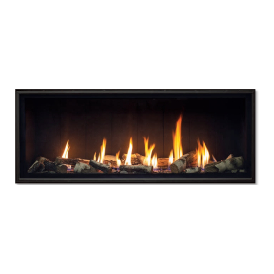
C60I-T
D I R E C T V E N T F I R E P L A C E - I P I
OWNER'S MANUAL
WARNING:
If the information in this manual is not followed exactly, a
fire or explosion may result causing property damage, personal injury
or loss of life. Installation and service must be performed by a qualified
installer, service agency or the gas supplier.
C#4001609
CERTIFIED TO/CERTIFIÉ AUX: ANSI Z21.88 / CSA 2.33 / CSA 2.17
1
50-4343
Version Française: www.enviro.com/fr.html
Advertisement
Table of Contents

Related Manuals for Enviro C60I-T


Summary of Contents for Enviro C60I-T
- Page 1 Installation and service must be performed by a qualified installer, service agency or the gas supplier. C#4001609 CERTIFIED TO/CERTIFIÉ AUX: ANSI Z21.88 / CSA 2.33 / CSA 2.17 50-4343 Version Française: www.enviro.com/fr.html...
-
Page 2: Safety Precautions
Safety Precautions WARNING: FIRE OR EXPLOSION HAZARD Failure to follow safety warnings exactly could result in serious injury, death, or property damage. - Do not store or use gasoline or other flammable vapors and liquids in the vicinity of this or any other appliance. - WHAT TO DO IF YOU SMELL GAS •... - Page 3 • Do not abuse the glass by striking it or slamming the door shut. TO TOUCH GLASS. • If the C60I-T unit is pulled out of its installation, and the A barrier designed to reduce the risk of burns from the...
-
Page 4: Table Of Contents
Table of Contents Safety Precautions ........................2 Table of Contents ........................4 Codes And Approvals ........................6 Specifications ..........................7 Dimensions ............................. 7 Rating Label & Lighting Instructions Location..................7 Operating Instructions ....................... 8 Lighting Instructions ........................8 Air Shutter (Venturi) ......................... - Page 5 Table of Contents Horizontal Vent install ........................32 Vertical Vent install .........................32 Outdoor Install ..........................33 Flex Venting ...........................34 Clearances & Non-Combustible ......................35 TV Installation Considerations ......................36 Vent Termination Restrictions ......................37 Direct Vent ............................37 Venting Clearances .........................38 Approved Venting Parts ........................39 Allowable Co-Axial Vent Configurations .....................40 Exhaust Restrictor Setting ........................42 Horizontal Termination .
-
Page 6: Codes And Approvals
This appliance has been tested by INTERTEK and found to comply with the established VENTED GAS FIREPLACE HEATER standards in CANADA and the USA as follows: VENTED GAS FIREPLACE HEATER (C60I-T ; NATURAL GAS, PROPANE GAS) TESTED AND LISTED TO: ANSI Z21.88 /CSA 2.33 VENTED GAS FIREPLACE HEATERS CSA 2.17 GAS FIRED APPLIANCES FOR HIGH ALTITUDES... -
Page 7: Specifications
Specifications imensions 9 - 1/8” [232 mm] 20” 17 - 3/8” [508 mm] [441 mm] 70 - 3/4” 1/2” [1797 mm] [13 mm] 7 - 1/4” [184 mm] 12” [305 mm] 44” 62” [1118 mm] 22 - 3/4” [1575 mm] 36 - 5/8”... -
Page 8: Operating Instructions
Operating Instructions For Your Safety, Read Safety Precautions And Lighting Instructions Before Operating WARNING: IF YOU DO NOT FOLLOW THESE INSTRUCTIONS EXACTLY A FIRE OR EXPLOSION MAY RESULT, CAUSING PROPERTY DAMAGE, PERSONAL INJURY OF LOSS OF LIFE. ighting nstRuctions FOR YOUR SAFETY READ BEFORE OPERATING WARNING: IF YOU DO NOT FOLLOW THESE INSTRUCTIONS EXACTLY, A FIRE OR EXPLOSION MAY RESULT CAUSING PROPERTY DAMAGE, PERSONAL INJURY OR LOSS OF LIFE. -
Page 9: Air Shutter (Venturi)
Proflame 2 is a modular remote control system that directs the functions of the C60I-T. The Proflame 2 transmitter (remote) is configured to control the on/off main burner operation, its flame levels and provides on/off and thermostatic control of the appliance. The system also controls the optional fan speed through six... -
Page 10: System Description
Operating Instructions ystem escRiption The Proflame 2 Remote Control System consists of two (2) elements: 1. Proflame 2 Transmitter. 2. Integrated Fireplace Controller (IFC) and wiring harness to connect to the gas valve, stepper motor battery holder, and convection fan. ATTENTION! - TURN “OFF”... -
Page 11: Integrated Fireplace Controller (Ifc)
Operating Instructions Key Lock Transmission Low battery alarm Thermostat OFF/ Room ON/SMART Temperature CPI mode Set Point Aux ON Temperature/Level/State Flame ON Split Flow Dimmer ON Comfort fan Figure 5: Proflame 2 Transmitter LCD Screen. (iFc) ntegRateD iRepLace ontRoLLeR The Proflame 2 IFC (Figure 6) connects directly to the gas valve, stepper motor, pilot, covection fans (optional) and light kit (optional) with a wiring harness. -
Page 12: Operating Procedure
When the C60I-T is turned off press the mode key to index to the constant pilot (CPI) mode icon (see Figure 8). Pressing the up arrow key will select Continuous Pilot Ignition (CPI) and pressing the down arrow key will return to IPI. - Page 13 Figure 11: Remote Control’s Flame Levels. Fan Control The C60I-T has a dual convection fan kit that can be controlled with the Transmitter. The fan speed can be adjusted thorugh six (6) speeds. To control the fan press the Mode key to index to the fan control icon.
- Page 14 The toplight uses a G9 25W 120V halogen bulb which can be replaced as needed or ordered under part number 50-4119. The C60I-T has TWO top light assemblies. Dimmer Control This is only appliciable if the light kit has been installed. Press the mode key until the light bulb symbol is visable (Figure 14).
-
Page 15: Maintenance And Service
The glass must be purchased from an ENVIRO dealer. No substitute materials are allowed. To remove the door (see page 17). The replacement glass will come with a new gasket installed. Remove any silicone remnants from the door. -
Page 16: Cleaning Decorative Surfaces
Maintenance And Service Leaning ecoRatiVe uRFaces Painted and porcelain faces should be wiped with a damp cloth periodically. If a plated face has been purchased, it should be unpacked/unwrapped carefully to avoid getting anything on the surface of the finish, including cleaners, polish and finger prints. -
Page 17: Glass Door Removal
Maintenance And Service Lass emoVaL First, remove the upper discharge, and bottom trim. Refer to section “Upper Discharge and Bottom Trim Removal” on page 16 for more information. To remove the glass door use a 3/8 socket to remove the 4 upper bolts and rotate outward. -
Page 18: Access Panels
Kit Parts List for C60I-T Model: 1 - Orifice (NG - #28 DMS or LP - #44 DMS) 2 - Conversion labels 1 - Installation instruction sheet 1 - Pilot Orifice (NG: 0.2) or (LP: 0.14) - Page 19 Maintenance And Service Carefully inspect all parts supplied with this conversion kit. If any parts have been damaged or are missing, contact your dealer, distributor or courier company to have them replaced before starting this installation. Conversion Kit Installation: 1. Turn the unit off by pressing the ON/OFF Key on the remote and shut off gas supply at the shut-off valve upstream of the unit.
- Page 20 Maintenance And Service 11. Convert the SIT gas valve: a. Use a T-20 driver to remove the two screws that hold the stepper regulator to the gas valve and disconnect the wire harness from the IFC. b. Remove the rubber regulator diaphragm that is situated between the stepper regulator and the valve body.
-
Page 21: Initial Installation
Initial Installation QUALIFIED INSTALLERS ONLY ntRoDuction This section of the owner’s manual is for the use of qualified technicians only. Fireplace placement, hearths, facing, mantels, and venting terminations will be covered, as well as the gas and electric systems. There are several installation safety guidelines that must be adhered to. -
Page 22: Steel Stud
Initial Installation QUALIFIED INSTALLERS ONLY teeL Framing of the fireplace requires a steel stud placed above the unit. The steel stud included with the fireplace comes in two pieces that combine to create a telescopic steel stud. This allows for horizontal adjustment to fit the specific length of your unit. -
Page 23: Placement And Framing
Initial Installation QUALIFIED INSTALLERS ONLY Lacement anD Raming 1” (25mm) Clearance from framing studs to venting S u p p l i e d S t e e l S t u d 78” 44” (1981mm) (1118mm) 71” (1803mm) 19½” (495mm) Figure 33: Construction Framing Dimensions Table 2: Framing Dimensions. -
Page 24: Cool Surface Activation
Initial Installation QUALIFIED INSTALLERS ONLY uRFace ctiVation WARNING: IT IS ESSENTIAL THAT THE CHASE IS VENTED IN A MANNER THAT RELIEVES THE ADDITIONAL HEAT ENTERING THE CHASE. ENSURE ONE OF THE AVAILABLE FRAMING OPTIONS HAVE BEEN CONSTRUCTED IN ACCORDANCE WITH THIS MANUAL. FAILURE TO DO SO CAN CREATE AN OVERHEATING SITUATION THAT COULD LEAD TO BUILDING FIRE. -
Page 25: Cool Surface Framing
Initial Installation QUALIFIED INSTALLERS ONLY uRFace Raming This appliance is manufactured with a built-in heat distribution kit, referred to as the Cool Surface System (CSS). The purpose of the CSS is to dramatically reduce the front wall temperatures above your appliance. This is very useful when delicate objects such as a TV or artwork are mounted above the unit. -
Page 26: Alternate Gas Inlet Location
LooR Rotection The C60I-T may be installed on a combustible floor. If the appliance is to be installed directly on carpeting, tile, or any other combustible material other than wood, the appliance must be installed on a metal or wood panel extending the full width and depth of the appliance. -
Page 27: Vent Termination Framing
Initial Installation QUALIFIED INSTALLERS ONLY eRmination Raming Minimum venting is shown in Figure 40. the framing height to the center of the thimble is 68”. Minimum venting must include a 24” vertical section and a 90 degree elbow which is then terminated horizontally. For a vertical termination please follow the vent pipe manufacturer’s installation instructions for vertical vent termination framing. -
Page 28: Mantel Requirements
Initial Installation QUALIFIED INSTALLERS ONLY anteL equiRements Refer to Figure 41 & Figure 42 for a combustible mantel installation, measurement is from bottom of the unit to the bottom of the mantel. The mantel height is drastically reduced when the CSS is activated. Refer to Figure 42 if the CSS is activated. - Page 29 Initial Installation QUALIFIED INSTALLERS ONLY If adding a mantel to the C60I-T please note the critical dimensions shown in Figure 43. These are minimum dimensions as per certification and must be followed. 6” Min 46 1 Minimum " Height 1170mm to Ceiling 8"...
-
Page 30: Installation With Recess
Initial Installation QUALIFIED INSTALLERS ONLY nstaLLation with ecess Refer to dimensions in Figure 44 if building a recess above the fireplace. Note the dimensions from the finishing edge to the stud below the recess finishing material. The vertical finishing material at the back of the recess must be be spaced 7/8”... -
Page 31: Corner Installation
Initial Installation QUALIFIED INSTALLERS ONLY oRneR nstaLLation The dimensions for installing a fireplace in the corner of a room are given in Figure 45. Refer to “I nstallatIon ” for allowable pipe lengths. llowaBle axIal onfIguratIons Do not interfere with the structural integrity of the walls. Shown below are minimum clearances; increasing these dimensions is allowable as long as vent length remains in the allowable range. -
Page 32: Horizontal Vent Install
Initial Installation QUALIFIED INSTALLERS ONLY oRizontaL ent instaLL Figure 47 shows a horizontal vent installation with minimum clearances. The horizontal vent shield must be used when the minimum vent configuration is used. If more than 24” of vertical rise is used the shield should not be installed. -
Page 33: Outdoor Install
QUALIFIED INSTALLERS ONLY utDooR nstaLL All Enviro C-Series fireplaces may be installed in a covered outdoor area when following the requirements stated below: • Fireplace must be installed in a weather proof enclosure while still following all clearance to combustible materials as outlined in the fireplace’s manual. -
Page 34: Flex Venting
Use 5X8 Flex Adapter Kit [50-3789]: This kit will allow you to adapt co-axial flex to the fireplace, make your vent run, then adapt back to rigid venting (flex not Any Enviro Approved included). Rigid Venting Any 5X8 CSA or UL flue gas certified aluminum or stainless steel flex is acceptable. -
Page 35: Clearances & Non-Combustible
The minimum clearance from the side of a mantle to wall is 4”. : There must be a minimum distance of 10” (254mm) from the bottom finishing edge of the C60I-T LooR to a floor composed of combustible material. -
Page 36: Tv Installation Considerations
Initial Installation QUALIFIED INSTALLERS ONLY tV i nstaLLation onsiDeRations If you are planning to mount a TV above your fireplace some considerations must be made to ensure it is protected from the heat. A recess, mantel, or a combination of both will be needed in order to keep the heat away from the TV. -
Page 37: Vent Termination Restrictions
Only Approved Direct Vent may be used for installation of the C60I-T. The minimum vent installation for the C60I-T must include a 24” vertical section and 90° elbow before being horizontally vented. Maximum vertical venting is 40’ (12.2 m). This model is vented with co-axial 5”... -
Page 38: Venting Clearances
Initial Installation QUALIFIED INSTALLERS ONLY 12 in (30 cm) 9 in (23 cm) Clearance to non-mechanical air supply inlet to building, or the combustion air inlet to any other appliance. 6 ft (1.83 m) 3 ft (91 cm) above if within 10 Clearance to mechanical air supply inlet. -
Page 39: Approved Venting Parts
Initial Installation QUALIFIED INSTALLERS ONLY ppRoVeD enting aRts Table 5: Approved Vent Manufacturers This fireplace has been tested and certified for use with the venting brand names liste Manufacturer Brand Name Nominal Sizes above in Table 5. Refer to Table 6 below for EXCELDirect 5”... -
Page 40: Allowable Co-Axial Vent Configurations
Initial Installation QUALIFIED INSTALLERS ONLY LLowabLe xiaL onFiguRations Figure 56 shows the range of venting options using either vertical or horizontal terminations; any layout that remains within the shaded area is acceptable. Having the fewest number of elbows is ideal as they tend to restrict air movement. - Page 41 Initial Installation QUALIFIED INSTALLERS ONLY If your C60I-T as been converted to 40’ LP using 50-3345 conversion kit, use (12.2m) this venting diagram. Flame Appearence: Pin point on the LP Vent map where your vent configuration will lay. Remember to consider elbows in the 35’...
-
Page 42: Exhaust Restrictor Setting
Initial Installation QUALIFIED INSTALLERS ONLY xhaust estRictoR etting WARNING: Improperly set restrictor setting can cause overheating issues which can lead to building fire. It may be necessary to adjust the exhaust restrictor in order to control combustion quality and flame appearance. -
Page 43: Horizontal Termination
Initial Installation QUALIFIED INSTALLERS ONLY oRizontaL eRmination . A MINIMUM OF 24” [610mm] VERTICAL RISE PLUS AN ELBOW IS REQUIRED WHEN HORIZONTALLY TERMINATING WITH AN APPROVED VENT CAP. 2. Horizontal pipes must not be level. For every 12” (305 mm) of horizontal travel (away from the stove), there should be at least ¼”... -
Page 44: Vertical Termination
Initial Installation QUALIFIED INSTALLERS ONLY Step 4. With the hole now framed, the wall thimble installed, and the pipe extending into the wall, proceed to the outside. Attach the termination to the pipe using RTV and Mil-Pac or Rutland No 78 Stove and Gasket Cement to seal joints. - Page 45 Initial Installation QUALIFIED INSTALLERS ONLY Step 5. Cut hole in the roof centered on the small hole placed in the roof from Step 2. The hole should be of sufficient size to meet minimum requirements for Clearance to Combustibles, as specified. Continue to assemble lengths of pipe and elbows necessary to reach from the ceiling support box up through the roof line.
- Page 46 Initial Installation QUALIFIED INSTALLERS ONLY NOTES: (1) If an offset is necessary in the attic to avoid obstructions, it is important to support the vent pipe every 3’ (914 mm), to avoid excessive stress on the elbows, and possible separation. Wall straps are available for this purpose (see Figure 63).
-
Page 47: Gas Line Connection And Testing
Initial Installation QUALIFIED INSTALLERS ONLY onnection anD esting WARNING: Only persons licensed to work with gas piping may make the necessary gas connections to this appliance. GAS LINE CONNECTION • This stove is equipped with a certified flexible pipe located on the right side of the unit terminating in a 3/8”... -
Page 48: Electrical Requirements
AWG wire with a temperature rating of 105°C Proflame 2 System - Wiring Diagram Transmitter - TMFLSA IPI Pilot 885 Gas Valve Battery Holder Main On/Off Main Harness Light(s) Optional Fan Kit Optional Light kit Power Cord Figure 66: C60I-T Wiring Diagram... -
Page 49: C60 Ipi Dual Covection Fan Kit (50-4173)
Initial Installation QUALIFIED INSTALLERS ONLY The C60I-T needs a hard-wired power connection in order for the unit to operate. There is also a battery pack that takes four AA batteries in case there is a power loss. All electrical connections must be made by a certified electrician. - Page 50 Receptacle Inside Cabinet Incoming Power Green White Black Figure 68: C60I-T Fan Kit Wiring Diagram Receptacle Gray Gray Inside Cabinet 3A Fuse Incoming Power Black Black Light Channel Assemblies Figure 69: Light Kit Wiring Diagram. C60I-T Light Kit Wiring Diagram.
-
Page 51: Secondary Installation
(50-3342) ight The C60I-T has an optional light kit that is wired into the IFC. The fireplace must be electrically connected and grounded in accordance with local codes or, in the absence of local codes, with the current CSA C22.1 Canadian Electrical Code Part 1, Safety Standards For Electrical Installations, or The National Electrical Code ANSI / NFPA 70 in the US.. -
Page 52: Bezel Installation
Secondary Installation ezeL nstaLLation The unit comes with a set of burner bezels. There are two long bezels, one short, and one short with a notch cutout. 1. Remove the safety screen and glass door 2. Place the bezels directly onto the burner platform as shown in Figure 71. No fasteners are required. 3. - Page 53 Wear clean vinyl gloves when handling 50-3340 (Enameled) to prevent smudging; use denatured alcohol to clean. Unwrap your new Enviro liner set from the protective packaging. Be careful not to scratch or bump the liners as they are very fragile. If the liners arrive damaged please contact your nearest Enviro dealer.
- Page 54 Secondary Installation 7. If you have media tray option 50-3343 (Glass Bezel) place the bezel strips around the tray before the side liners are installed. If you are using 50-3344 (Glass Media Bed) or 50-3342 (Light Kit) install tray media after the side liners.
-
Page 55: Trouble Shooting
Trouble Shooting Table 9: Troubleshooting Problem Possible Cause Solution · Turn the system off by pressing the ON/OFF button on the transmitter · After approximately 2 seconds press the ON/OFF button on the transmitter again. Locking Reset the Proflame IFC board ·... -
Page 56: Parts Diagram
Parts Diagram... -
Page 57: Parts List
Parts List Table 10: C60I-T Parts List Reference # Part Description Part # C60T Pan Burner w/ Pilot Shield N/C 50-4306 C60T Door Complete 50-4307 C60T Safety Screen Complete 50-4308 C60T Clear View Screen Only 50-4309 C60T Slim Line Surround... -
Page 58: Notes
Notes... - Page 59 Sherwood Industries Ltd. (“Sherwood”) hereby warrants, subject to the terms and conditions herein set forth, this product against defects in material and workmanship An expanded list of exclusions is available at www.enviro.com/help/warranty.html during the specified warranty period starting from the date of original purchase at retail.
- Page 60 _________________________________________ _________________________________________ NATURAL GAS (NAT) PROPANE(LPG) _________________________________________ INLET GAS PRESSURE:_________in wc PHONE:___________________________________ MAIN BURNER ORIFICE:__________# DMS PILOT ORIFICE #_________OR________in diam. INSTALLER’S SIGNATURE: _________________________________________ MANUFACTURED BY: SHERWOOD INDUSTRIES LTD. 6782 OLDFIELD RD. SAANICHTON, BC, CANADA V8M 2A3 www.enviro.com April 2023 C-16695...
Need help?
Do you have a question about the C60I-T and is the answer not in the manual?
Questions and answers