
Related Manuals for Dräger Medical Oxylog 3000


Summary of Contents for Dräger Medical Oxylog 3000
- Page 1 Technical Documentation Oxylog 3000 Emergency and transport ventilator Revision 4.0 5503.403 9036041 Because you care...
-
Page 3: Table Of Contents
Contents General Symbols and Definitions Notes Function Description General introduction Monitoring ..........................5 Area of application ........................5 Principle of operation Pneumatic system Inlet ............................6 Metering ..........................6 Sensors and safety functions ....................7 PEEP valve ..........................8 Ambient pressure conditions ....................9 Electronics Charging circuit PCB ...................... - Page 4 Contents Maintenance Procedures Replacing the filter element Replacing the internal battery Schematics and Diagrams General introduction Annex Parts catalog Test List Technical Information...
- Page 5 General...
- Page 7 Devicename General Symbols and Defini- tions WARNING A WARNING statement provides important information about a poten- tially hazardous situation which, if not avoided, could result in death or serious injury. CAUTION A CAUTION statement provides important information about a potentially hazardous situation which, if not avoided, may result in minor or moderate injury to the user or patient or in damage to the equipment or other prop- erty.
- Page 8 General Devicename Know-how contained in this Technical Documentation is subject to ongoing change through research and development and Dräger Medical reserves the right to make changes to this Technical Documentation without notice. NOTE Unless otherwise stated, reference is made to laws, regulations or stan- dards (as amended) applicable in the Federal Republic of Germany for equipment used or serviced in Germany.
- Page 9 Function Description...
-
Page 11: General Introduction
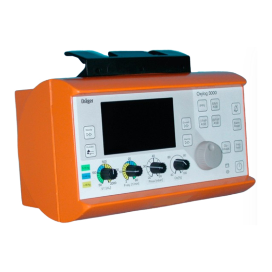
Function Description General introduction Oxylog 3000 is an emergency and transport ventilator for short-time treat- ment of lung damage of a wide variety of kinds. It provides timed and volume- controlled ventilation, as well as assisting the patient’s breathing in pressure- controlled mode. -
Page 12: Pneumatic System
Function Description Oxylog 3000 Figure 1 Principle of operation Pneumatic system The following description relates to the pneumatic components diagram Oxy- log 3000. The evaluation of the measurement signals from the sensors and operation of the valves is handled on the control PCB. -
Page 13: Sensors And Safety Functions
Oxylog 3000 Function Description With the valve V1 and the ejector E1 ambient air can additionally be drawn in. Valve V1 meters a flow through the ejector. The resultant negative pressure draws ambient air through the filter F2, the flow sensor S2 and the non-return valve V9. -
Page 14: Peep Valve
Function Description Oxylog 3000 Figure 2 Block diagram of external flow sensor The pressure sensor S5 measures the pressure at the patient. Based on this pressure value, the control PCB makes calculations including for actuation of the PEEP valve V6. -
Page 15: Ambient Pressure Conditions
Figure 3 Ventilation valve Ambient pressure Oxylog 3000 meters the tidal volume under BTPS conditions. Sensors S7 conditions and S9 measure the ambient pressure. S5 measures the current pressure level in the lung. In this way the control PCB can balance fluctuating ambient pressure and the BTPS conditions (Body Temperature, Pressure, Saturated. -
Page 16: Sensor Pcb
Function Description Oxylog 3000 Sensor PCB The sensor PCB holds all the pressure sensors of the pneumatic system and the internal temperature gauge. The sensor PCB is the interface for pressure measurement and valve actuation between the pneumatic and electronic sys- tems. - Page 17 Maintenance Procedures...
- Page 19 Oxylog 3000 Maintenance Procedures Replacing the filter 1. Switch off the unit. element 2. Remove screws Figure Figure 1 Removing the filter element NOTE Note fitting position of filter element. 3. Remove the filter element. 4. Install the new filter element.
- Page 20 The internal battery can be charged by the battery charger station or by the external power supply in the Oxylog 3000. 6. Fit the internal battery. 7. Switch on the Oxylog 3000 and check the battery capacity indicated on the display. 5503.403...
- Page 21 Schematics and Diagrams...
- Page 23 Oxylog 3000 Schematics and Diagrams 5503.403...
- Page 24 Schematics and Diagrams Oxylog 3000 5503.403...
- Page 25 Oxylog 3000 Schematics and Diagrams 5503.403...
- Page 26 Schematics and Diagrams Oxylog 3000 5503.403...
- Page 27 Oxylog 3000 Schematics and Diagrams 5503.403...
- Page 28 Schematics and Diagrams Oxylog 3000 5503.403...
- Page 29 Oxylog 3000 Schematics and Diagrams 5503.403...
- Page 30 Schematics and Diagrams Oxylog 3000 5503.403...
- Page 31 Oxylog 3000 Schematics and Diagrams 5503.403...
- Page 32 Schematics and Diagrams Oxylog 3000 5503.403...
- Page 33 Oxylog 3000 Schematics and Diagrams 5503.403...
- Page 34 Schematics and Diagrams Oxylog 3000 5503.403...
- Page 35 Annex Parts catalog Test List Technical Information...
- Page 37 Parts catalog Oxylog 3000 Revision: 2006-02-01 11:37:13 5503.403 Because you care...
- Page 39 Item Qty. Part No. Description Qty. Remark unit 2M86955 Oxylog 3000 1.000 2M86300 Oxylog 3000 1.000 Items that are shown in the illustration but are not listed below the illustration are not available as spare parts 5503.403 Revision: 2006-02-01 11:37:13...
- Page 40 Parts catalog Product concerned Item Qty. Part No. Description Qty. Remark unit 5703300 Caddy 1.000 Items that are shown in the illustration but are not listed below the illustration are not available as spare parts 5503.403 Revision: 2006-02-01 11:37:13...
- Page 41 Parts catalog Accessories/Consumables Item Qty. Part No. Description Qty. Remark unit 5703303 BAG OXYLOG 1000 FOR CADDY 1.000 5703304 BAG OXYLOG 2000 FOR CADDY 1.000 5703305 Bag for CompactCaddy 1.000 5703306 PROTECTION COVER 1.000 5703307 Carrying Belt 1.000 5704216 All-round Wall Holder 1.000 5704218 Wall Holder Adaptation Plate...
- Page 42 Parts catalog Caddy Item Qty. Part No. Description Qty. Remark unit 5703310 CLAW_FOR_CADDY 1.000 5703329 PROTECTION BAR HIGH FOR CADDY 1.000 5703328 PROTECTION BAR LOW FOR CADDY 1.000 5703341 CYLINDER FIXATION SET 1.000 5703336 PROTECTION FOOT CADDY 1.000 5703340 GUIDING RAIL SET FOR CADDY 1.000 5703367 PROTECTION STRIP CADDY...
- Page 43 Parts catalog CompactCaddy Item Qty. Part No. Description Qty. Remark unit 5703310 CLAW_FOR_CADDY 1.000 5703333 GUIDING RAIL FOR COMPACTCADDY 1.000 5703335 PROTECTION FOOT Compact CADDY 1.000 Items that are shown in the illustration but are not listed below the illustration are not available as spare parts 5503.403 Revision: 2006-02-01 11:37:13...
- Page 44 Parts catalog Front Item Qty. Part No. Description Qty. Remark unit M29655 CONTROL KNOB 1.000 1830015 COVER 1.000 2M86697 Cover 1.000 Items that are shown in the illustration but are not listed below the illustration are not available as spare parts 5503.403 Revision: 2006-02-01 11:37:13...
- Page 45 Parts catalog Pneumatic Item Qty. Part No. Description Qty. Remark unit 8403735 Set of 5 Spirolog sensors 1.000 Items that are shown in the illustration but are not listed below the illustration are not available as spare parts 5503.403 Revision: 2006-02-01 11:37:13...
- Page 46 Parts catalog Pneumatic Item Qty. Part No. Description Qty. Remark unit 2M86341 Filter Mat 1.000 Items that are shown in the illustration but are not listed below the illustration are not available as spare parts 5503.403 Revision: 2006-02-01 11:37:13...
- Page 47 Parts catalog Dosing block Item Qty. Part No. Description Qty. Remark unit 1-11 ME05170 Spare part dosage block 1.000 Items that are shown in the illustration but are not listed below the illustration are not available as spare parts 5503.403 Revision: 2006-02-01 11:37:13...
- Page 48 Parts catalog Carrying System 3000 Item Qty. Part No. Description Qty. Remark unit 2M86737 Carrying System 1.000 2M86631 Alduk I O2-DM G3/4 1.000 2M86632 Alduk II O2-DM G3/4 1.000 2M86678 Alduk II O2-DM Pin Index 1.000 B10205 O2 Bottle 2L-200bar-G3/4-GFK 1.000 B10208 O2 Bottle 2L-200bar-PIN-GFK...
- Page 50 SUPPLY MAIN, 3M 1824481 GUIDING RAIL FOR COMPACTCADDY 5703333 TEST LUNG 8403201 GUIDING RAIL SET FOR CADDY 5703340 Vent hose disp Oxylog 3000 set 2M86841 IfU Caddy und CompactCaddy me 9038011 Wall Holder 2M86940 IfU Carrying System 3000 me 9037752...
- Page 51 Test List (TL) Oxylog 3000 Notes on field of application: This test list can be processed with standard commercially available test aids and tools, but does not replace the inspections and maintenance work carried out by the manufacturer. Tests marked with the symbol '(√ )' are listed in the 'Test list report“ and can be documented there.
- Page 52 ........................1 Serial number (SN)....................... 1 Software ........................1 2 Electrical safety..........................2 Oxylog 3000 - not applicable - ..................2 AC/DC power pack ....................... 2 3 Function and condition test......................3 Accompanying documentation ..................3 Visual check ......................... 3 Safety valve ........................
-
Page 53: Device Configuration
Device configuration Serial number (SN) (√ ) [ __________ ] 1.1.1 Oxylog 3000 The serial number is located on the rating plate. Software (√ ) [ __________ ] 1.2.1 Software version The software version is displayed on-screen immediately after power-up. -
Page 54: Electrical Safety
The AC/DC power pack is categorized as protection class I (safety insulated). Measure to VDE 0751 or IEC 601. 2.2.1 Equivalent device leakage current test 1. Connect output of AC/DC power pack to Oxylog 3000. (√ ) μ [ _____ 2.2.1.1... -
Page 55: Function And Condition Test
Accompanying documentation Instructions for Use are available. [OK] (√ ) Visual check The condition of the Oxylog 3000 is assessed by a visual check. 3.2.1 Housing The housing is not contaminated by dirt or damaged. The labels are clearly legible. -
Page 56: Unit Test
1. Set the unit to Customer Service mode (see also "Annex"). 2. Activate "Test loudspeaker, buzzer, LEDS and display" test step. 3. Run the complete test. The tests of the loudspeaker, the buzzer, the LEDs and the display were successful. [OK] 4/11 5503.403 Oxylog 3000 Released 2002-03-07... -
Page 57: Voltage Supply
The "No battery" message is no longer displayed. [OK] 6. Remove external power supply. The unit continues ventilating. − The external power LED is unlit. − The internal replaceable battery charge indicator LED is unlit. 5/11 5503.403 Oxylog 3000 Released 2002-03-07... -
Page 58: Supply Pressure/Emergency Air Valve
7. Connect the compressed gas supply. − The acoustic alarm stops. − The red alarm LED is no longer lit. − Ventilation is resumed with the previous settings. [OK] 8. Press the "Alarm Reset" button. 6/11 5503.403 Oxylog 3000 Released 2002-03-07... -
Page 59: Ventilation
Pressure-controlled ventilation 1. Remove test specimens and connect test thorax in their place. 2. Make the following settings: − Ventilation mode = BIPAP − Frequency = 6 1/min − Alarm limit Pmax = 60 mbar 7/11 5503.403 Oxylog 3000 Released 2002-03-07... - Page 60 The test thorax inflates to a PEEP pressure of 10 mbar. [OK] No self-triggering occurs. [OK] The message "O2 setting not possible" may appear. The message can be ignored. 2. Trigger using the test thorax. 8/11 5503.403 Oxylog 3000 Released 2002-03-07...
-
Page 61: Unit Handover
The unit triggers and activates a ventilation stroke. At the same moment a "star" appears on the top line of the display. [OK] (√ ) 3.10 Unit handover Place fully functional unit at the user’s/owner’s disposal. [OK] 9/11 5503.403 Oxylog 3000 Released 2002-03-07... -
Page 62: Test Equipment
Measuring range to 1000 mbar Test lung (test thorax) Test lung, comprising the following components: Breathing bag 2 litre breathing bag to simulate lung compliance. Catheter socket diameter 7 To simulate the airway impedance. 10/11 5503.403 Oxylog 3000 Released 2002-03-07... -
Page 63: Annex
Now the appropriate test can be selected and activated. To quit Service mode switch off the unit. The values set in Customer Service mode are retained and reactivated every time ventilation is started following power- 11/11 5503.403 Oxylog 3000 Released 2002-03-07... - Page 64 Test List Report Oxylog 3000 Test List Edition: 2002-03-07 Installation site: __________ OK Result OK Result Device configuration Serial number (SN) ( ) 1.1.1 Oxylog 3000 [ __________ ] Software ( ) 1.2.1 Software version [ __________ ] Electrical safety AC/DC power pack 2.2.1...
- Page 65 Carrying System3000 2M86975 The Oxylog 3000 should not be used adjacent to or stacked with other equipment; if adjacent or stacked use is inevitable, the Oxylog 3000 should be observed to verify normal operation in the configuration in which it will be used.
- Page 66 Field strengths from fixed, portable or mobile rf transmitters at the location of the Oxylog 3000 should be less than 3 V/m in the frequency range from 150 kHz to 2.5 GHz and less than 1 V/m above 2.5 GHz.
- Page 67 Recommended separartion distances Recommended separation distances between portable and mobile RF-Telecommunication devices and the Oxylog 3000 max. 3 V/m dis- 1 V/m dis- Hint tance* (m) tance* (m) EIRP 0.001 0.06 0.17 0.003 0.10 0.30 0.010 0.18 0.55 0.030 0.32 0.95...
- Page 69 Manufacturer: Support: Dräger Medical b.v. Dräger Medical AG & Co. KG Kanaaldijk 29 Moislinger Allee 53 – 55 NL-5683 CR BEST D-23542 Lübeck The Netherlands Germany Phone: (+31) 499 331 - 331 Phone: (+49) (0) 1805-3723437 Fax: (+31) 499 331 - 335 Fax: (+49) 451/882 - 3779 Subject to change without notice Will not be replaced in the event of modifications.
Need help?
Do you have a question about the Oxylog 3000 and is the answer not in the manual?
Questions and answers