Table of Contents
Advertisement
Quick Links
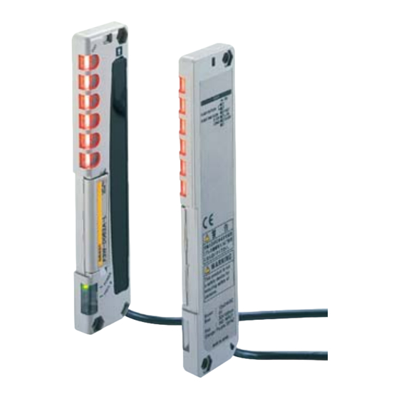
Picking Sensor
F3W-D
Compact, Resistant to Mutual
Interference, and Ideal for Picking a
Variety of Parts.
• Mounts to a parts rack and uses indicators to show parts
picking procedures. Functions as a mistake-proofing
Sensor.
• Models with direct UNI-WIRE connection are also
available.
• Use either the built-in LED indicators or external picking
indicators.
Be sure to read Safety Precautions on
page 8.
Features
Sensing Distance of 3 m
Selectable Display Mode: All Lighting,
All Flashing, Elevator-like Lighting,
Accordion-like Lighting
• Six picking indicators provide very clear displays.
• Selectable display speed (slow/fast)
All lit
All flashing
http://www.ia.omron.com/
Elevator effect
Accordion effect
External Picking Indicators Can Be
Connected
An external indicator can be directly connected to the Picking Sensor
and mounted in an easy-to-see location.
F3W-D052@P
External
indicator
(c)Copyright OMRON Corporation 2008 All Rights Reserved.
1
Advertisement
Table of Contents

Subscribe to Our Youtube Channel
Related Manuals for Omron F3W-D


Summary of Contents for Omron F3W-D
- Page 1 Accordion-like Lighting • Six picking indicators provide very clear displays. • Selectable display speed (slow/fast) All lit All flashing Elevator effect Accordion effect F3W-D052@P External indicator http://www.ia.omron.com/ (c)Copyright OMRON Corporation 2008 All Rights Reserved.
-
Page 2: Ordering Information
Mounting Brackets Protective Bracket Appearance Model Remarks Appearance Model L-shaped Mounting One each for Emitter and Bracket Receiver F39-L10 F39-L12 (mounting screws (mounting screws included) included) Flat Mounting Bracket F39-L11 (mounting screws included) http://www.ia.omron.com/ (c)Copyright OMRON Corporation 2008 All Rights Reserved. - Page 3 MAF-S407FEO (ITOH Building) TEL(052)322-3481 FAX(052)322-3483 Note: Consult an NKE sales office for purchasing information. Kyoto Sales Office, 336-1 Hazukashi Hishikawacho, Fushimi-ku, Kyoto 612-8487 TEL(075)924-3293 FAX(075)924-3290 Toll-free TEL number: 0120-77-2018 (Only in Japan) http://www.ia.omron.com/ (c)Copyright OMRON Corporation 2008 All Rights Reserved.
-
Page 4: Ratings And Specifications
*2. Response time includes transfer delay time. *3. The transmission indicator indicates bus transmission status. *4. The following cable lengths are also available. F3W-D052A (P): 2 m, 7 m F3W-D052B (P): 1 m, 3.5 m http://www.ia.omron.com/ (c)Copyright OMRON Corporation 2008 All Rights Reserved. -
Page 5: Engineering Data (Typical)
Distance X −100 −10 −10 −150 −200 −15 −15 (1) Horizontal Movement (2) Vertical Movement (1) Emitter Angle Characteristics (2) Receiver Angle Characteristics Characteristics Characteristics θ θ θ θ Tilt Rotation Tilt Rotation http://www.ia.omron.com/ (c)Copyright OMRON Corporation 2008 All Rights Reserved. - Page 6 (orange) The instruction input address is set with DIP switch 2. OFF: One beam UNI-WIRE output Picking instruction or more is input (transmission input) interrupted Picking indicator (orange) External picking indicator output http://www.ia.omron.com/ (c)Copyright OMRON Corporation 2008 All Rights Reserved.
-
Page 7: Setting Method
The transmission indicator indicates the status of local (separate) power supply. − bus transmission as follows: − Flashing: Normal operation ON or OFF: Transmission error Only one picking indicator flashing also indicates a transmission error. http://www.ia.omron.com/ (c)Copyright OMRON Corporation 2008 All Rights Reserved. -
Page 8: Safety Precautions
Sensors with the same frequency setting, a beam from the (2) The F3W-D is designed for detection of the human body or moving Emitter of one Sensor may hit the Receiver of the other Sensor, objects in the detection area but not for protection against danger. - Page 9 Make sure that the Emitter and Receiver detect Distance X the sensing object properly before using the F3W-D in actual operation. Side View...
- Page 10 Standard length: 5 m 44.7 F3W-D052U(P)-D: Vinyl-insulated round * F3W-D052U(P)-D only cable with four conductors, 4 dia. M12 × 1 Conductor: 0.3 mm 5 poles Insulation: 1.2mm dia. 14.9 dia. Standard length: 2 m http://www.ia.omron.com/ (c)Copyright OMRON Corporation 2008 All Rights Reserved.
- Page 11 (Thickness: 2 mm) Mounting screws provided. Mounting Brackets F3W-D052A-D with Mounting Bracket F39-L11 (Flat) Four mounting holes Five 10.8 Material: Iron Four, 4.8 dia. 23.25 optical (Thickness: 2 mm) axes Mounting screws provided. http://www.ia.omron.com/ (c)Copyright OMRON Corporation 2008 All Rights Reserved.
- Page 12 6 dia. 45.5 (110/0.08 dia.) Nominal wire diameter: AWG20 8.5 dia. 44.7 13.6 Blue marking Y-shaped Joint Plugs and Sockets without Cable Wiring Diagram XS2R-D526-S003 4.5 dia. 24.5 (37) 12.5 58.3 Blue marking http://www.ia.omron.com/ (c)Copyright OMRON Corporation 2008 All Rights Reserved.
- Page 13 Warranty and Limitations of Liability WARRANTY OMRON's exclusive warranty is that the products are free from defects in materials and workmanship for a period of one year (or other period if specifi ed) from date of sale by OMRON. OMRON MAKES NO WARRANTY OR REPRESENTATION, EXPRESS OR IMPLIED, REGARDING NON-INFRINGEMENT, MERCHANTABILITY, OR FITNESS FOR PARTICULAR PURPOSE OF THE PRODUCTS.
Need help?
Do you have a question about the F3W-D and is the answer not in the manual?
Questions and answers