
Related Manuals for Westinghouse iGen1500c


Summary of Contents for Westinghouse iGen1500c
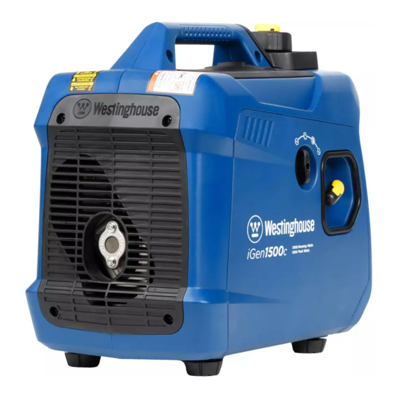
- Page 1 USER MANUAL iGen1500c DIGITAL INVERTER GENERATOR 1000 RUNNING WATTS | 1500 PEAK WATTS DO NOT RETURN THIS PRODUCT TO THE STORE If you have questions or need assistance, please call customer service at 855-944-3571.
-
Page 2: Table Of Contents
IMPORTANT: Keep your purchase receipt for trouble- UPDATES free warranty coverage. The latest User Manual for your Westinghouse products can be found under our support tab. wpowereq.com/pages/manuals Or scan the following QR code with your smartphone camera to be directed to the link. -
Page 3: Introduction
If you have a question or experience a problem Maximum wattage and current are subject to and with your Westinghouse purchase, call us at limited by such factors as fuel BTU content, ambient 1-855-944-3571 to speak with an agent. -
Page 4: Safety
SAFETY SAFETY DEFINITIONS SAFETY SYMBOLS The words DANGER, WARNING, CAUTION, and Follow all safety information contained in this user’s NOTICE are used throughout this manual to highlight manual as well as the information on the product important information. Make sure that the meanings labeling. - Page 5 SAFETY FIG. 1 IMPORTANT SAFETY INSTRUCTIONS DANGER Generator exhaust contains high levels of carbon monoxide (CO), an invisible, odorless, and extremely poisonous gas. If you smell exhaust fumes, you are breathing carbon monoxide. But, even if you do not smell exhaust fumes you may be inhaling CO.
- Page 6 SAFETY NOTE: A transfer switch must be installed by a qualified l Before starting the generator, check all fluids (oil and electrician in accordance with applicable electrical gasoline). codes. Some jurisdictions may require the installation l Do not remove the oil dipstick or fuel cap when the to be inspected by local authorities.
- Page 7 SAFETY FIG. 3 The generator neutral is floating. The generator ground terminal is connected to the frame of the generator, the metal non-current-carrying parts of the generator, and the ground terminals of each receptacle. The generator (stator winding) is isolated from the frame and from the AC receptacle ground pin.
- Page 8 SAFETY IMPORTANT INFORMATION FOR THE UNDERSTANDING THE CO SENSOR’S CO SENSOR INDICATOR LIGHTS See Figure 4. The CO Sensor monitors for the accumulation of poisonous carbon monoxide gas around the generator COLOR DESCRIPTION when the engine is running. If increasing levels of CO Unsafe levels of carbon monoxide gas are detected, the CO Sensor automatically shuts accumulated around the generator.
- Page 9 SAFETY SAFETY LABELS AND DECALS The following information is on your generator’s labels and decals. 1 California Proposition 65 Cancer and reproductive harm - www.P65Warnings.ca.gov/product 2 Safety Symbols (See page 4) 3 Specifications (See page 3) 4 Action Label If unsafe levels of carbon monoxide accumulate around generator,...
-
Page 10: Electrical
ELECTRICAL GENERATOR CAPACITY EXTENSION CORDS NOTICE WARNING Do not overload the generator’s Asphyxiation hazard. capacity. Exceeding the generator’s wattage/ Extension cords running directly into the home amperage capacity can damage the generator and/ increase the risk of carbon monoxide poisoning or electrical devices connected to it. -
Page 11: Components
COMPONENTS FIG. 5 A - Output Ready LED H - 120 Volt AC 20 Amp Receptacles O - Recoil Handle B - Overload LED I - 20 Amp Circuit Breaker P - Vented Fuel Cap C - Low Oil LED J - Main Circuit Breaker (9 Amp) Q - Spark Plug Service Door D - Service Generator LED... -
Page 12: Assembly
PARALLEL OPERATION OUTLETS The main circuit breaker protects the generator from A parallel cord (not included) can be used to connect overloads during parallel operation. a compatible Westinghouse inverter generator for additional power output. MUFFLER AND SPARK ARRESTOR RECOIL HANDLE The spark arrestor prevents sparks from exiting the muffler. -
Page 13: Operation
OPERATION KNOW HOW TO SAFELY LOCATE AND DANGER Generator exhaust contains OPERATE YOUR GENERATOR high levels of carbon monoxide (CO), an invisible, odorless, and extremely poisonous gas. If you DANGER Asphyxiation hazard. Place the smell exhaust fumes, you are breathing carbon generator in a well-ventilated area. - Page 14 OPERATION KNOW THE REGULATIONS FOR THE USE FIG. 6 OF PORTABLE GENERATORS Consider where and how you intend to use your generator, and familiarize yourself with any local, state, or federal ordinances concerning your intended use. It may be necessary to contact a qualified electrician or local governing agency for a full list of requirements.
- Page 15 OPERATION FIG. 8 l Replace the oil dipstick and hand-tighten. l Install the engine service cover and turn the lock knob to the locked position to secure. GASOLINE REQUIREMENTS NOTICE Do not use E15 or E85 fuel in this product. Engine or equipment damage caused by stale fuel or the use of unapproved fuels (such as E15 or E85 ethanol blends) is not covered by warranty.
- Page 16 OPERATION HIGH ALTITUDE OPERATION handle rapidly away from the generator until the engine starts. Engine power is reduced the higher you operate above NOTE: Gently return the recoil handle into place after sea level. Output will be reduced approximately 3.5% starting the unit.
- Page 17 LED to illuminate before putting the ECO mode switch in the ON position. NOTICE Do not use ECO mode when in parallel operation with another Westinghouse inverter generator. ECO mode minimizes fuel consumption and noise by adjusting the engine RPM to the minimum required for the current load.
- Page 18 Parallel operation gives you the ability to link to a compatible Westinghouse Inverter Generator for A - 20 Amp Circuit Breaker B - 9 Amp Circuit Breaker combined running and peak power output.
-
Page 19: Care And Maintenance
CARE AND MAINTENANCE l Remove the engine service cover. WARNING Accidental start-up. Disconnect l Gently depress the latch on the side of the air filter cover the spark plug boot (see figure 18) from the and remove the cover. spark plug when performing maintenance on the l Remove the air filter from the air cleaner housing and generator. - Page 20 See Figure 16. FIG. 16 NOTICE ALWAYS 0.024 - 0.032 in. Westinghouse OEM or compatible non-resistor- (0.60 - 0.80 mm) type spark plug. Use of resistor-type spark plug can result in rough idling, misfire, or may prevent the engine from starting.
- Page 21 CARE AND MAINTENANCE CLEANING THE SPARK ARRESTOR FIG. 17 See Figure 17. Check and clean the spark arrestor according to the figures specified in the maintenance schedule or the engine manual (if applicable). Failure to clean the spark arrestor will result in degraded engine performance. l Turn the generator off and allow the engine to cool for 30 minutes.
- Page 22 CARE AND MAINTENANCE FIG. 19 To run the float bowl dry: l Start the generator as described earlier. l After the engine starts, turn the engine/fuel control switch to the GASOLINE OFF position. l Allow the generator to run until the fuel in the carburetor is depleted and the engine stops.
- Page 23 CARE AND MAINTENANCE CHECKING/ADJUSTING VALVE FIG. 22 CLEARANCE See Figures 22 - 23. NOTICE Checking and adjusting valve clearance must be done when the engine is cold. l Turn the generator off and allow the engine to cool for 30 minutes. l Place the generator on a level surface in a well- ventilated area.
- Page 24 Change oil every month when operating under heavy load or in high temperatures. Clean more often under dirty or dusty conditions. Replace air filter if it cannot be adequately cleaned. Recommend service to be performed by authorized Westinghouse service dealer. 24 | English...
-
Page 25: Troubleshooting
Contaminated gasoline. Drain the fuel tank. Refuel with fresh shuts down gasoline. Defective low oil level switch. Contact Westinghouse customer service toll-free at 1 (855) 944-3571. Air filter restricted. Clean or replace air filter. Stale gasoline, generator stored without Drain the fuel tank. Refuel with fresh treating or draining gasoline, or refueled with gasoline. - Page 26 Westinghouse are trademarks of Westinghouse Electric Corporation. Used under license by MWE Investments, LLC. © 2022 MWE Investments, LLC All Rights Reserved. iGen4500DFc 122035 Rev01 07/21 122515 Rev02 08/22 iGen1500c Rev 01...
Need help?
Do you have a question about the iGen1500c and is the answer not in the manual?
Questions and answers