
Related Manuals for Westinghouse iGen4500s


Summary of Contents for Westinghouse iGen4500s
- Page 1 Digital Inverter Generators Instruction Manual iGen1200 iGen2200 iGen2500 iGen4500s...
- Page 3 CONGRATULATIONS ON PURCHASING A WESTINGHOUSE DIGITAL INVERTER GENERATOR Thank you for purchasing a Westinghouse portable generator. It is a high-quality power product that will provide many years of safe and reliable service if properly operated and maintained. DANGER This manual contains important instructions for operating the generator. For your safety and that of others, be sure to read this manual thoroughly before operating the generator.
-
Page 4: Table Of Contents
& 2500 Starting ..........................17 iGen4500s Electric Starting ........................18 iGen4500s Manual Starting ........................18 iGen4500s Wireless Remote Starting .......................19 iGen4500s Pairing the Remote Control Fob and Generator ..............19 ECO THROTTLE CONTROL ..........................19 OVERLOAD RESET ............................20 STOPPING THE GENERATOR .........................20 Normal Operation ............................20 During an Emergency ..........................20... - Page 5 Cleaning the Air Filter ..........................29 FUEL STRAINER MAINTENANCE ........................30 SPARK PLUG MAINTENANCE ........................31 SPARK ARRESTER MAINTENANCE .......................33 CLEANING THE GENERATOR .........................34 12 VOLT BATTERY MAINTENANCE iGen4500s ....................34 Charging the Battery ..........................34 Replacing the Battery ..........................35 REMOTE CONTROL FOB MAINTENANCE .....................35 DRAINING THE FUEL ............................35 LONG-TERM STORAGE ..........................36...
-
Page 6: Safety
SAFETY SAFETY DEFINITIONS SAFETY SYMBOL DEFINITIONS The words DANGER, WARNING, CAUTION and Symbol Description NOTICE are used throughout this manual to highlight important information. Be certain that the meanings of these alerts are known to all who work Safety Alert Symbol on or near the equipment. -
Page 7: General Safety Rules
SAFETY GENERAL SAFETY RULES WARNING DANGER Petrol fuel liquid and vapours are extremely flammable and explosive Never use the generator in a location under certain conditions. that is wet or damp. Never expose the • Always refuel the generator generator to rain, snow, water spray outdoors, in a well-ventilated area. - Page 8 SAFETY WARNING WARNING Never operate the generator if: You must take reasonable care for powered items overheat; electrical the health and safety both of yourself output drops; there are sparks, flames and any others who may be affected or smoke coming from the generator; by your actions.
-
Page 9: Safety Labels
Do not refuel the generator while engine is running. WARNING WARNING Read Unleaded Instruction Petrol Manual Only Westinghouse Outdoor Power Equipment, LLC 777 Manor Park Drive, Columbus OH 43228 USA westinghouseoutdoorpower.com.au N15626 IP23 Made in Vietnam Figure 1 - Safety Labels... -
Page 10: Unpacking
1. Carefully cut the packing tape on top of the D – Instruction Manual carton. 2. Fold back top flaps to reveal the upper packing E – Remote Control Fob (for iGen4500s) tray. 3. Remove and save the instruction manual, oil bottle, oil funnel and spark plug socket wrench. -
Page 11: Features
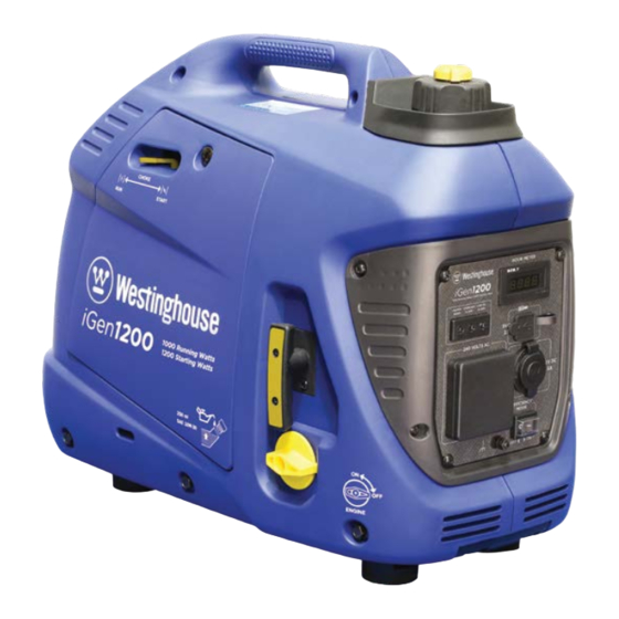
FEA TURES MAIN GENERATOR COMPONENTS iGen1200 - Carry Handle - Engine Access Cover - Fuel Cap and Vent - Choke Lever - Control Panel - Spark Plug Access Cover - Engine and Fuel Control Switch - Exhaust Pipe - Recoil Starter Handle - Muffler Access Cover Figure 3 - iGen1200 Main Generator Components... -
Page 12: Control Panel Features Igen1200
FEA TURES CONTROL PANEL FEATURES iGen1200 Run Time (hours) 1. Output Indicator: The green status light will 6. 12-Volt DC Accessory Socket: Can be used for illuminate whenever the engine is running and 12-Volt DC powered devices up to a maximum there is AC output available from the generator. -
Page 13: Main Generator Components Igen2200 & 2500
FEA TURES MAIN GENERATOR COMPONENTS iGen2200 & 2500 - Carry Handle - Spark Plug Access Cover - Fuel Cap and Vent - Exhaust Pipe with Spark Arrester - Control Panel - Muffler Access Cover - Recoil Starter Handle - Engine Access Cover Figure 5 - iGen2200 &... -
Page 14: Control Panel Features Igen2200 & 2500
FEA TURES CONTROL PANEL FEATURES iGen2200 & 2500 Run Time (hours) 1. Output Indicator: The green status light will 5. 240-Volt AC, 15-Amp Outlet: The outlet is capable illuminate whenever the engine is running and of delivering the generator’s peak output of there is AC output available from the generator. -
Page 15: Main Generator Components Igen4500S
- Muffler Access Cover - Control Panel - Exhaust Pipe with Spark Arrester - Extendable Handle - Battery Access Cover - Wheel - Oil Access Cover - Engine Access Cover - Recoil Starter Handle Figure 7 - iGen4500s Main Generator Components... -
Page 16: Control Panel Features Igen4500S
Run Time (hours) Empty (hours) (kW) (litres) Figure 8 - iGen4500s Control Panel Features 1. 240-Volt AC, 15-Amp Outlets: Each outlet is 4. Low Oil Alarm: The red warning light will capable of delivering the generator’s peak illuminate and the engine will automatically shut output of 4,500 Watts (i.e. - Page 17 FEA TURES 8. Generator Reset Button: Press and hold down this button to reset the generator’s electrical output when safe to do so after reducing the applied load or rectifying the electrical fault that has caused an overload trip. 9. Data Center: The alphanumeric LED display shows the cumulative run time, run time to empty at current load, output power, fuel level and output voltage in a repeating cycle.
-
Page 18: Operation
OPERA TION CONNECTING THE BATTERY Tools required – None. iGen4500s 1. Remove the battery access cover by pressing down on its locking tab and pulling it away from WARNING the generator (see Figure 9). To avoid electric shock: • ALWAYS connect the positive (+) battery cable (red boot) first when connecting battery cables. -
Page 19: Before Starting The Generator
OPERA TION BEFORE STARTING THE 3. Locate the two halves of the battery wiring harness connector. GENERATOR 4. Assemble the connector by firmly pushing Location Selection – Before starting the generator, the two halves together; each of the two male avoid exhaust and location hazards by verifying that: pins should be inserted into the corresponding female socket on the other half of the connector... -
Page 20: Checking Or Adding Engine Oil And Fuel
3. Move the generator to a flat surface. 4. Clean area around the fuel cap. 5. Turn the fuel cap vent clockwise to the ON position (not applicable to the iGen4500s). -
Page 21: Starting The Generator
OPERA TION 6. Remove the fuel cap by unscrewing it anti- DANGER clockwise. 7. Slowly add fuel into the fuel tank. Be careful not Never use the generator in a location to overfill the tank. The fuel level should NOT be that is wet or damp. -
Page 22: Igen2200 & 2500 Starting
OPERA TION 2. Turn the engine and fuel control switch anti- clockwise to the ON position (see Figure 14). Figure 16 – Recoil Starter Handle Operation Figure 14 – Engine and Fuel Control Switch in the iGen2200 & 2500 Starting ON Position 1. -
Page 23: Igen4500S Electric Starting
NOTE: There is no need to alter this starting procedure dependent upon the engine temperature. The iGen4500s is equipped with an automatic choke. Figure 18 – Fuel Control Switch in the ON Position 3. -
Page 24: Igen4500S Wireless Remote Starting
Figure 20 – Wireless Remote Control Fob 1. Turn the fuel control switch clockwise to the ON position (see Figure 18). iGen4500s Pairing the Remote 2. Push the engine control switch to the central AUTO RUN position (see Figure 19). -
Page 25: Overload Reset
OFF button for at least one second and then release it. WARNING Figure 21 – ECO Throttle Switch in the ON Position If stopping the iGen4500s by remote To deactivate ECO mode, move the ECO throttle control, use audible or visual means switch to the OFF position. -
Page 26: Ambient Conditions
OPERA TION AMBIENT CONDITIONS NOTICE The generator is designed to operate within the DO NOT connect any 240-Volt AC device that is following range of ambient conditions: fitted with a three-pin 20 A plug. This can overload the generator. • Temperature: -5 to +40°C •... -
Page 27: Power Output And Demand
OPERA TION More complex 240-Volt AC devices containing inductive or capacitive elements such as electric motors have a momentary extra power demand when starting, which can be up to seven times the running power demand or more. Manufacturers of such devices rarely publish this starting power demand and so it’s often necessary to estimate it. -
Page 28: 240-Volt Ac Extension Cords
OPERA TION 240-VOLT AC EXTENSION 12 VOLT BATTERY CHARGING CORDS Depending on the model, there are either one or two methods by which the generator can be used to Wherever possible, it is recommended to connect charge an external 12 Volt battery: 240-Volt AC devices directly to the generator’s 240- A. -
Page 29: Battery Charging By A Mains-Powered Charger
OPERA TION 5. Insert the cigarette lighter plug into the alligator clip or terminal clamp (black) to the generator’s 12-Volt DC accessory socket. The negative (-) terminal on the battery. battery is now charging. Keep the battery as far 4. Start the generator. away as possible from the generator due to the 5. -
Page 30: Transporting The Generator
Locking Button Handle Grip The iGen4500s’ wheels are only intended for ease of moving the generator around by hand. The wheels are not suitable for towing the generator either on or Figure 25 - iGen4500s Extendable Handle off-road. -
Page 31: Maintenance
Alternatively, an authorised Westinghouse service dealer can carry out this work for a fee. Table 1: Basic Maintenance Schedule - Owner Performed... -
Page 32: Engine Oil Maintenance
MAINTENANCE Table 2 lists the more complicated maintenance tasks that are best performed by a qualified mechanic using specialised tools. It is recommended to engage an authorised Westinghouse service dealer to carry out this work. Table 2: Advanced Maintenance Schedule - Authorised Westinghouse Service Dealer Performed... -
Page 33: Adding Engine Oil
Tools required - iGen1200, 2200 & 2500: Phillips head screwdriver and oil drain pan or oil extractor vacuum pump. iGen4500s: Oil drain pan or oil extractor vacuum pump. SAE 10W-30 1. Stop the engine, if running. -
Page 34: Air Filter Maintenance
NOTICE Never dispose of used engine oil by dumping Figure 34 - iGen4500s Removing the Engine the oil into a sewer, on the ground, or into Access Cover groundwater or waterways. Always be 4. -
Page 35: Fuel Strainer Maintenance
MAINTENANCE iGen4500s: Remove the air filter cover by turning NOTICE the twistlocks anti-clockwise and tipping the cover forwards (see Figure 37). Clean the air Never dispose of the used cleaning solution or filter cover with a rag and place it aside. -
Page 36: Spark Plug Maintenance
10. Re-install the fuel cap. SPARK PLUG MAINTENANCE Tools required – Phillips head screwdriver (iGen1200 & 4500s), 10 mm socket wrench (iGen4500s), spark plug socket wrench, spark plug gap tool or feeler gauge, and wire brush. Figure 42 - iGen2200 & 2500 Removing the Spark... - Page 37 MAINTENANCE • Spark plug gap of 0.7 mm or 0.028 inch (see Figure 45); after cleaning with a wire brush, check using a spark plug gap tool or feeler gauge and adjust by carefully bending the ground electrode. Always check the gap of a new spark plug before installing it.
-
Page 38: Spark Arrester Maintenance
Then tighten the adjusting screw on the band clamp. Figure 47 – iGen4500s Removing the Muffler 9. iGen2200 & 2500: Re-install the muffler access Access Cover cover. -
Page 39: Cleaning The Generator
1. Ensure the generator is stopped and the engine 12 VOLT BATTERY control switch is in the STOP position. 2. Allow the generator to cool down if it has been MAINTENANCE iGen4500s running. The generator’s 12 Volt battery is a sealed-for-life WARNING type that requires no regular maintenance. -
Page 40: Replacing The Battery
Step 9 instead of the old one. It is recommended to use a genuine replacement battery purchased from an authorised Westinghouse Figure 50 – Emptying the Fuel Tank Outdoor Power Equipment dealer or service agent for optimum fit and performance. -
Page 41: Long-Term Storage
If this is not possible, the generator should be prepared for long-term storage as described hereunder. Figure 53 – iGen4500s Draining the Carburettor Proper care should be taken to prepare the generator for any long-term storage. This will protect the generator’s function and appearance, and will make it easier to start when next required. -
Page 42: Storage Procedure For Greater Than 3 Months
Dismantling should only be carried out by a mechanically proficient person with access to proper tools or alternatively by your authorised Westinghouse service dealer for a fee. Before dismantling: 1. Stop the generator (see Stopping the Generator). 2. Drain the engine oil (see Changing Engine Oil). -
Page 43: Troubleshooting
12. Check air filter element and clean if necessary. 13. Spark arrester is dirty or 13. Check spark arrester and clean if necessary. blocked. 14. If above possible causes 14. Take generator to an authorised Westinghouse are checked and eliminated, service dealer. generator may be faulty. - Page 44 Engine is running, but illuminated, generator may generator and press the generator reset button no 240-Volt AC output is (iGen4500s only). If unresolved, stop and re-start be faulty. available. engine with ECO throttle switch in the OFF position. If still unresolved, take generator to an authorised Westinghouse service dealer.
- Page 45 Damage caused to the generator by excessive or faulty DC loads is not covered by warranty. If above possible causes Take generator to an authorised Westinghouse are checked and eliminated, service dealer. generator may be faulty. Generator is out of fuel.
- Page 46 Drain fuel and refill with fresh fuel. contaminated. Air filter is dirty or blocked. Check air filter element and clean if necessary. If above possible causes Take generator to an authorised Westinghouse are checked and eliminated, service dealer. generator may be faulty.
-
Page 47: Specifications
SPECIFICA TIONS PARAMETER iGen1200 iGen2200 iGen2500 iGen4500s Type 1-Cylinder, 4-Stroke, Overhead Valve, Air Cooled Displacement (cm Max. Speed (rpm) 5,200 5,300 5,500 3,600 Oil Capacity (mL) Low Oil Shutdown Spark Plug Torch A5RTC Torch E6RTC Torch E6RTC Torch F7RTC Fuel... -
Page 48: Wiring Diagrams
WIRING DIAGRAMS iGen1200 WIRING DIAGRAM... -
Page 49: Igen2200 & 2500 Wiring Diagram
WIRING DIAGRAMS iGen2200 & 2500 WIRING DIAGRAM... -
Page 50: Igen4500S Wiring Diagram
WIRING DIAGRAMS iGen4500s WIRING DIAGRAM 12V DC Accessory Socket DC Coil DC Rectifier Alternator 5V DC USB Socket Sub Coil AC Sockets Main Coil Br/R Overload Indicator Light Output Indicator Inverter Light Supply Coil Efficiency Switch Reset Bu/W Stepping Motor... -
Page 51: Warranty
Consumer or Westinghouse Outdoor Power Equipment (the others without the Company’s prior written approval. “Company”) warrants that its Westinghouse portable To the extent permissible by law and electric generators (the “Goods”) shall be free from... - Page 52 NOTES...
- Page 53 NOTES...
- Page 54 NOTES...
- Page 56 Parkinson QLD 4115 Australia www.westinghouseoutdoorpower.com.au © 2019 All rights reserved. Content may change without notice. , Westinghouse, and INNOVATION YOU CAN BE SURE OF are trademarks of the Westinghouse Electric Corporation used under license by Westinghouse Outdoor Power Equipment, LLC.
Need help?
Do you have a question about the iGen4500s and is the answer not in the manual?
Questions and answers