
Related Manuals for Getinge 7800A Series


Summary of Contents for Getinge 7800A Series
- Page 1 OPERATOR MANUAL 61301604768 Rev. C 7800A SERIES FLOOR MOUNTED CART AND UTENSIL WASHER...
- Page 3 OPERATOR MANUAL 7800A SERIES FLOOR MOUNTED CART AND UTENSIL WASHER Getinge USA, Inc. 1777 East Henrietta Road Rochester, New York 14623-3133 Phone: (800) 950-9912 Facsimile: (800) 950-2570...
- Page 4 “Notes” alert the user to pertinent facts and conditions. NOTE This manual contains proprietary information of Getinge, USA. It shall not NOTE be reproduced in whole or in part without the written permission of Getinge, USA. • POSSIBILITY OF INJURY: Misuse of equipment may result in personal injury.
-
Page 5: Table Of Contents
Table of Contents SPECIAL SAFETY INSTRUCTIONS ....VII SAFETY LABELS USED ON THE EQUIPMENT ..VIII Section 1 General Description INTRODUCTION . - Page 6 Wash ........1–8 Rinse .
- Page 7 7800A Series Floor Mounted Cart and Utensil Washer Disable Low Dispenser Supply Faults ... . 3–19 Change the Tank Cycle Count....3–20 Change the Supervisor Password .
- Page 8 Appendix C Consumable Stock and Spare Parts CONSUMABLE STOCK......C–1 SPARE PARTS ....... . . C–2...
-
Page 9: Special Safety Instructions
7800A Series Floor Mounted Cart and Utensil Washer Special Safety Instructions THE FOLLOWING SAFETY INSTRUCTIONS APPEAR WITHIN THIS MANUAL. READ THEM CAREFULLY BEFORE OPERATING THE UNIT. "Warning" notes alert the user to the possibility of personal WARNING injury. Running a Cycle p. -
Page 10: Safety Labels Used On The Equipment
Safety Labels Used on the Equipment The following safety labels are used on the 7800A washer: You must remove all power to the washer before removing the back cover to the washer chamber light assembly. CAUTION High voltage is present inside the control box. You must remove all power to the washer before opening the door to the control box. -
Page 11: Section 1 General Description
Section 1 General Description Introduction The Model 7800A is a fully automatic, large capacity, hydro-spray washer that is used to clean and dry case carts, stands, utensils, containers, tote boxes, and similar bulk items. Routine operation consists of loading the compartment, closing the door, and touching a START button. -
Page 12: Options
General Description The 7800A washer is available in three models based on load length. Table 1–1. 7800A Floor Mounted Cart and Utensil Washer Model Load Length Overall Cabinet 78003 80" (2032 mm) 71" W x 108" H x 88" L 78004 98"... -
Page 13: Accessories
7800A Series Floor Mounted Cart and Utensil Washer Accessories The following accessories are available for the 7800A washer. Floor Mounted Ramps Stainless steel ramps are provided standard with the floor mounted washer. Utensil and Container Processing Carts Three processing carts for utensils and rigid containers are available for use with the washer. -
Page 14: Exterior Components
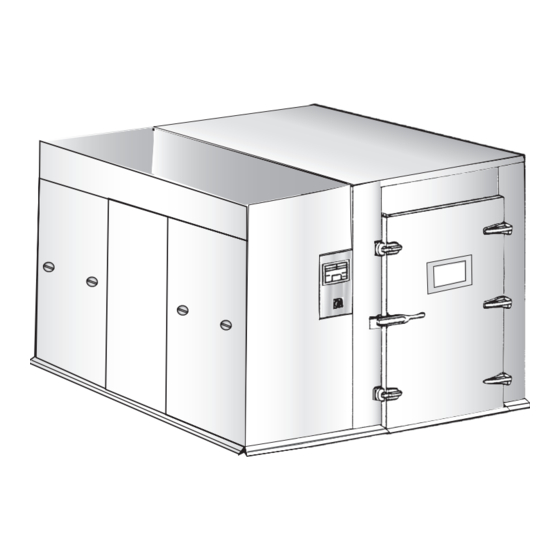
General Description Exterior Components Figure 1–2. Exterior Components UNLOAD END DOOR DOOR SWITCH UNLOAD END INDICATOR PANEL SERVICE AREA LOAD END DOOR DISPENSERS CONTROL CONTROL POWER PANEL ON/OFF RESET SWITCH HW-002 Unload End Indicator Panel The IN OPERATION indicator lights yellow for the duration of an ongoing processing cycle. -
Page 15: Service Area
7800A Series Floor Mounted Cart and Utensil Washer Service Area Provides access to components such as plumbing, valves, pumps, holding tank, control box, and manifold drive motor. The optional service area is enclosed by removable panel sections. Alarm (Not Shown) Sounds an audible alert: •... -
Page 16: Interior Components
General Description Interior Components Figure 1–3. Interior Components SPRAY MANIFOLD DRIVE ASSEMBLY GUIDE RAIL SPRAY MANIFOLD FLOOR GRATES SUMP HW-003 Spray Manifold Drive Continuously moves the manifold system back and forth along the length of Assembly the compartment during a processing cycle. Exhaust Duct The chamber includes a flanged vent to connect to the building exhaust system. -
Page 17: Heated Air Duct
7800A Series Floor Mounted Cart and Utensil Washer Heated Air Duct Enables hot air to be circulated through the compartment to dry the load after the final rinse phase. Guide Rails Restraints for loaded utensil carts to protect the manifolds when the floor tilts during a cycle. -
Page 18: Processing Cycle Description
General Description Processing Cycle Description The 7800A washer runs the following processing cycle. Tank Fill Hot water fills the holding tank while detergent is injected automatically for a period necessary to bring the solution to the required detergent concentration. As the tank fills, the steam coil brings the water up to the programmed wash temperature of 140 °F to 150 °F (60 °C to 66°C). -
Page 19: Section 2 Touch Control Panel
Section 2 Touch Control Panel Overview The touch control panel provides the operator with a touch screen interface to the programmable logic controller located in the control box. The controls on the panel enable the operator to: • Select and start a processing cycle. •... -
Page 20: Description
Touch Control Panel Description To activate the touch control panel, the PC POWER switch located near the NOTE bottom in the control box must be set to ON. This switch is normally set to ON at installation and left in that position. When the touch control panel is activated, an indicator in the lower-left corner of the panel lights green and the screen displays the Power Up panel until communications with the processor is established and the Main panel... - Page 21 7800A Series Floor Mounted Cart and Utensil Washer DAILY LOAD COUNT Displays the washer’s current load count (the number of cycles that the washer has processed since the resetable counter was set). TANK CYCLES REMAINING Displays the number of cycles that are remaining before the holding tank is automatically drained and filled with fresh wash solution.
- Page 22 Touch Control Panel CYCLE REVIEW AND PROGRAM / CYCLE REVIEW ONLY If the cycle is not protected (the button label is CYCLE REVIEW AND PROGRAM), touching this button displays the Cycle Setup panel (see page 2–6) for the selected cycle, which enables you to: •...
-
Page 23: Numeric Keypad Panel
7800A Series Floor Mounted Cart and Utensil Washer If the tank is empty, touching START begins to fill the tank. When the tank is NOTE full, the wash phase begins, although phase timing does not begin until the wash solution reaches its programmed temperature. -
Page 24: Cycle Setup Panel
Touch Control Panel Cycle Setup Panel The Cycle Setup panel appears when you touch CYCLE REVIEW AND PROGRAM on the Main panel (the selected cycle is not protected). If the washer has the standard rinse, the panel shown in Figure 2–3 appears. If the purified rinse option is installed on your washer, the panel shown below in Figure 2–4 appears. - Page 25 7800A Series Floor Mounted Cart and Utensil Washer The cycle that is selected on this panel when you return to the Main panel NOTE becomes the current cycle. WASH/RINSE/PURIFIED RINSE/DRYING/EXHAUST TIME Displays the duration for the wash, rinse or pure rinse, drying, and exhaust phases.
-
Page 26: Cycle Review Panel
Touch Control Panel Cycle Review Panel The Cycle Setup panel appears when you touch CYCLE REVIEW ONLY on the Main panel (the selected cycle is protected). If the washer has the standard rinse, the panel shown in Figure 2–3 appears. If the purified rinse option is installed on your washer, the panel shown below in Figure 2–4 appears. -
Page 27: In Cycle Panel
7800A Series Floor Mounted Cart and Utensil Washer The remaining indicators on this panel display the current parameters for the selected cycle. The indicators on this panel are similar to those that appear on the Cycle Setup panel (see page 2-6), except that you cannot change any of these parameters and that the indicators on this panel are light blue (they are dark blue on the Cycle Setup panel). - Page 28 Touch Control Panel DETERGENT and RINSE AID Status Indicators These indicators display information about the detergent and rinse aid dispensers. One of these messages is displayed: • DETERGENT/RINSE AID READY — this is the normal state for the dispenser when it is not pumping liquid. •...
-
Page 29: Supervisor Panel
7800A Series Floor Mounted Cart and Utensil Washer Supervisor Panel Figure 2–8. Supervisor Panel 3-10 This panel enables a supervisor to perform these administrative functions: • specify one or more processing cycles as “protected.” • disable the low level dispenser alarms. - Page 30 Touch Control Panel PRIME RINSE AID/DETERGENT PUMP / RINSE AID/DETERGENT PUMP PRIMING Touching one of these buttons starts the pump on the corresponding dispenser. The pump runs until you touch the button again. TANK CYCLE COUNT Displays a data entry keyboard, which enables you to specify the number of cycles (up to 20) that run before the tank is drained and refilled.
-
Page 31: Time And Date Panel
7800A Series Floor Mounted Cart and Utensil Washer Time and Date Panel Figure 2–9. Time and Date Panel This panel appears when you touch the SET TIME AND DATE button on the Supervisor panel. The current date and time are displayed on the panel. -
Page 32: Cycle Count Panel
Touch Control Panel Cycle Count Panel Figure 2–10. Cycle Count Panel RESET THE DAILY COUNT Touching this button resets the DAILY LOAD COUNT to 0. DAILY LOAD COUNT Displays the number of cycles that have run since the last time this counter was reset. -
Page 33: Section 3 Operating Instructions
Section 3 Operating Instructions General Washer Operation Starting Up the Washer To activate the touch control panel, the PC POWER switch located near the NOTE bottom in the control box must be set to ON. This switch is normally set to ON at installation and left in that position. - Page 34 Operating Instructions When the processor has established communications with the screen, the Main panel appears. Figure 3–2. Main Panel 2. To start up the washer, set the CONTROL POWER ON OFF/RESET switch to ON. The CONTROL POWER IS OFF button changes to START. Figure 3–3.
-
Page 35: Loading A Utensil Cart
7800A Series Floor Mounted Cart and Utensil Washer Loading a Utensil Cart The utensil and container wash carts are designed to hold an assortment of racks. You can interchange racks as needed simply by lifting the rack off the cross rods, tilting it approximately 30 degrees, and either moving it to a different set of cross rods or removing it altogether. -
Page 36: Running A Cycle
Operating Instructions Running a Cycle The instructions in this section apply to the daily operation of the washer. The instruction assumes that the washer has been properly installed and pre-tested, the washer is powered on, the compartment is clean, cycles have been programmed, the liquid dispensers have been set up, and optional equipment is ready for operation. - Page 37 7800A Series Floor Mounted Cart and Utensil Washer 1. Open the load end door and move the load into the washer compartment. The message LOAD DOOR OPEN appears on the touch control panel. Figure 3–5. Main Panel 2. Close the door securely.
- Page 38 Operating Instructions Figure 3–7. In Cycle Panel The selected processing cycle begins after a short delay (5 seconds by default) so that any residual pressure within the compartment can be relieved. This 5 second delay can be changed at any time by service personnel. NOTE If necessary, the holding tank starts to fill.
-
Page 39: Normal In-Cycle Messages
7800A Series Floor Mounted Cart and Utensil Washer While the unload end door is open, the panel displays UNLOAD IN PROGRESS. When the unload end door is closed, the display changes to UNLOAD COMPLETE, then to READY. Normal In-Cycle Messages The table below provides a list of messages that may be displayed during normal error-free processing. - Page 40 Operating Instructions Table 3–1. Normal In-Cycle Status Messages (Continued) MESSAGE COLOR EXPLANATION EXHAUST PHASE Green The exhaust phase is currently running. The panel displays the time remaining for this phase. LOAD & UNLOAD Both doors are open. DOORS OPEN LOAD DOOR OPEN The load end door is open.
-
Page 41: Extending A Cycle
7800A Series Floor Mounted Cart and Utensil Washer Table 3–1. Normal In-Cycle Status Messages (Continued) MESSAGE COLOR EXPLANATION TANK EMPTY Yellow When the washer is initially powered up PRESS “FILL TANK” (at the beginning of the day, for example) or after a manual drain, you must touch the FILL TANK button. -
Page 42: Draining The Holding Tank And Sump
Operating Instructions Draining the Holding Tank The holding tank and sump are normally drained at the end of the cycle and Sump specified by the TANK CYCLE COUNT. If you have to empty the tank and sump before that time, the DRAIN TANK/SUMP button enables you to do it manually. -
Page 43: Emergency Stop
7800A Series Floor Mounted Cart and Utensil Washer Emergency Stop • Burn hazard. Do not open a washer door for at least 30 WARNINGS seconds after stopping a processing cycle that was running a wash or rinse phase. This delay allows time for the spray manifolds to stop functioning. -
Page 44: Emergency Stop Using The Control Power On Off/Reset Switch
Operating Instructions Emergency Stop Using the To perform an emergency shutdown of the washer using the CONTROL CONTROL POWER ON POWER ON OFF/RESET switch. OFF/RESET Switch 1. Set the CONTROL POWER ON OFF/RESET switch to OFF. The washer stops operating and the Main panel appears, and the START button changes to CONTROL POWER IS OFF. -
Page 45: Operating The Liquid Supply Dispensers
7800A Series Floor Mounted Cart and Utensil Washer Operating the Liquid Supply Dispensers Description While the washer’s holding tank is filling for the first cycle, the detergent dispenser automatically pumps liquid detergent into the hot water supply in the tank. The dispenser operates for a period that depends on the flow rate of the pump, which is measured when the washer is installed, and the desired concentration of detergent in the wash water. -
Page 46: Prime A Dispenser Pump
Operating Instructions Prime a Dispenser Pump Use this procedure when the supply is initially set up, when you change the liquid supply, or any time the dispenser tubing is empty. 1. Insert the float switch assembly into the dispenser’s liquid supply container. -
Page 47: Enter The Detergent Concentration
7800A Series Floor Mounted Cart and Utensil Washer Enter the Detergent The processor determines how long to pump detergent into the holding tank Concentration based on the flow rate of the pump and the recommended concentration of detergent. To enter the detergent concentration: 1. -
Page 48: Supervisor Operations
Operating Instructions Supervisor Operations Programming a Cycle The washer enables you to select from four independent processing cycles. These cycles are preset with the time and temperature values listed in Table 3–2 below. You can retain these values or change them as desired to meet your specific needs. - Page 49 7800A Series Floor Mounted Cart and Utensil Washer Figure 3–12. Cycle Setup Panel 2. If necessary, touch one of the SELECT CYCLE buttons to select the cycle you want to program. The TIME and TEMP buttons display the current setpoint values for the phases of the selected cycle.
- Page 50 Operating Instructions The numeric keypad panel for that setpoint appears. 4. Type the new value, touch Enter, and then touch Done. 5. Repeat steps 4 and 5 for each setpoint that you want to change. 6. To turn the floor tilt feature on or off, touch the FLOOR TILT button.
-
Page 51: Disable Low Dispenser Supply Faults
7800A Series Floor Mounted Cart and Utensil Washer Disable Low Dispenser The washer reports an error if the detergent or rinse aid supplies run low. If Supply Faults you do not override this fault, the washer does not start the next cycle until you refill the appropriate liquid supply and reset the fault. -
Page 52: Change The Tank Cycle Count
Operating Instructions Change the Tank Cycle 1. On the Main panel, touch SUPERVISOR AND SERVICE Count SCREEN. A numeric keypad panel appears. 2. Type the supervisor password and touch Enter. The Supervisor panel appears. Figure 3–14. Supervisor Panel 3-10 3. Touch TANK CYCLE COUNT. A numeric keypad panel appears. -
Page 53: Change The Supervisor Password
7800A Series Floor Mounted Cart and Utensil Washer Change the Supervisor To change the supervisor password. Password 1. On the Main panel, touch SUPERVISOR AND SERVICE SCREEN. A numeric keypad panel appears. 2. Type the supervisor password and touch Enter. -
Page 54: Set The Time And Date
Operating Instructions Set the Time and Date To program the time and date for the washer. 1. On the Main panel, touch SUPERVISOR AND SERVICE SCREEN. A numeric keypad panel appears. 2. Type the supervisor password and touch Enter. The Supervisor panel (Figure 3–15 on page 3–21) appears. -
Page 55: Reset The Daily Load Count
7800A Series Floor Mounted Cart and Utensil Washer Reset the Daily Load Count To reset the load count. 1. On the Main panel, touch SUPERVISOR AND SERVICE SCREEN. A numeric keypad panel appears. 2. Type the supervisor password and touch Enter. -
Page 56: Protect Or Unprotect A Cycle
Operating Instructions Protect or Unprotect a Cycle To change a cycle to either protected or unprotected. 1. On the Main panel, touch SUPERVISOR AND SERVICE SCREEN. A numeric keypad panel appears. 2. Type the supervisor password and touch Enter. The Supervisor panel (see Figure 3–15 on page 3–21) appears. -
Page 57: General Maintenance Schedule
Monthly equipment and information on • Check Supply Hoses our Performance Assurance • Check Dispenser Pump/Tubes Plan, contact Getinge USA, Inc. • Descale Sump 1777 East Henrietta Road, Rochester, NY 14623-3133 or • Check and Clean Steam Traps Every 6 call 1-800-950-9912. -
Page 58: Routine Maintenance Schedule
Maintenance Routine Maintenance Schedule When Required Loading Printer Paper See “Paper Roll Loading” on page A-2. Daily Inspect and Clean Washer Surfaces 1. Inspect the exterior and interior surfaces of the washer. 2. Clean with mild detergent and a soft, damp cloth. Check Liquid Supplies 1. - Page 59 7800A Series Floor Mounted Cart and Utensil Washer Clean the Tank Debris Screen To clean the debris screen in the tank. 1. Loosen the thumbscrew securing the cover to the tank and open the cover. Figure 4–2. Tank Debris Screen...
-
Page 60: Weekly
Maintenance Weekly Clean the Screen on the Return Pump Low Suction Collar Figure 4–3. Remove Return Pump Cover LOW SUCTION COLLAR 1/4-20 FASTENERS FRONT SUMP COVER 1. Remove the two 1/4-20 fasteners that secure the low suction collar to the pump. 2. -
Page 61: Monthly
7800A Series Floor Mounted Cart and Utensil Washer Monthly Flush Spray Manifold Flushing the spray manifold removes any fine debris that may have accumulated in the assembly due to the recirculation of wash/rinse water during routine operation. 1. Remove the hex head plug or drain check assembly from the bottom of each manifold leg. - Page 62 Descale Sump Descale the sump and steam heating coil surfaces to prevent a buildup of mineral deposits. Contact your Getinge/Castle Service Technician for an appropriate scale remover and follow the directions for its use. 1. Turn the detergent and rinse-aid dispensers off by removing the power cables from connectors J23 and J24 on the control box.
-
Page 63: Every Six Months
7800A Series Floor Mounted Cart and Utensil Washer Every Six Months Check and Clean Steam Traps 1. Check all steam traps. This task should be performed by qualified service personnel. NOTE 2. Clean if required. Check and Clean Y-Strainers 1. Check the filter screens in all plumbing supply lines. - Page 64 Maintenance 4. Using a small flat-head screwdriver, pry open the battery access slot on the top of the power supply module and pull the holder out. Figure 4–6. PLC Battery PLC BATTERY BATTERY CONNECTOR 5. Remove the battery and install its replacement. Ensure the plus (+) side of the battery faces the front of the PLC.
-
Page 65: Error Messages
Section 5 Troubleshooting Error Messages If an error occurs that forces the cycle to stop, the Main panel will be displayed and the error will be displayed (Figure 3–5 on page 3–5). If an error condition occurs that does not force the cycle to stop, the error will be displayed on the In Cycle panel as illustrated in Figure 5–1 below. - Page 66 Troubleshooting Table 5–1. In-Cycle Resetable Error Messages MESSAGE COLOR EXPLANATION DRYER There is a problem with the steam TEMPERATURE supply. TIMEOUT FLOOR POSITION There is a jammed floor panel or a bad FAILURE switch. EMERGENCY CORD The emergency stop cable is broken or BROKEN has come loose.
-
Page 67: Non-Resetable Error Messages
7800A Series Floor Mounted Cart and Utensil Washer If the condition persists and the message occurs again: 1. Set the CONTROL POWER ON OFF/RESET switch to OFF. 2. Notify qualified service personnel. Non-resetable Error A list of non-resetable error messages is provided in Table 5–2 below. - Page 68 Troubleshooting 5–4...
-
Page 69: Description
Appendix A Recorder/Printer The optional recorder/printer provides a record of pertinent cycle data for each processing cycle that runs on the washer. Pertinent data includes cycle identification, programmed phase setpoints, phase performance, date, and time. The recorder/printer is equipped with a thermal array print head that is capable of printing at a paper feed rate of 1.3 inches per second. -
Page 70: Feed/On/Off Switch
Recorder/Printer Refer to Figure A–1. FEED/ON/OFF Switch Turns the recorder/printer on and off. When you hold the switch in the FEED position, the switch rapidly advances the paper through the recorder/printer. STATUS Indicator The indicator lights: • green when the recorder/printer is turned on. •... - Page 71 7800A Series Floor Mounted Cart and Utensil Washer 6. Turn the FEED ON OFF switch to the FEED position and hold until approximately 12 inches of paper is discharged from the output slot. 7. Run the end of the paper through the access cover’s input slot and wrap it around the take-up reel.
-
Page 72: Operation
Recorder/Printer Operation Operation of the recorder/printer is automatic and does not require the attention of personnel other than for routine replacement of the paper roll (see page A–2). • Do not operate the printer without paper. NOTE • The final few feet of a paper roll are shaded red to indicate that the supply is running out. -
Page 73: Flow Rate
Appendix B Liquid Dispenser Setup Successful cleaning of equipment by your washer depends on having the recommended amounts of detergent and rinse aid solution in the wash and rinse phases. This appendix provides instructions to ensure that the appropriate quantities of these solutions are used. Determine the Detergent Dispenser Flow Rate The processor controls the amount of time that the detergent dispenser pump runs when the tank is initially filled and again during the drying phase... - Page 74 Liquid Dispenser Setup The Service panel appears. Figure B–1. Service Panel 4. Touch SERVICE TIMERS. The Service Timers panel appears. Figure B–2. Service Timers Panel 5. Touch ENTER DETERGENT OFFSET. A numeric keypad panels appears. 6. Enter the time (in seconds) that you calculated above in step 1, touch Enter, and then touch Done.
-
Page 75: Rinse Aid Dispenser Calibration
7800A Series Floor Mounted Cart and Utensil Washer Rinse Aid Dispenser Calibration Refer to Table B–1 on page B-4. Rinse aid solution is injected directly into the rinse water. The desired flow rate of the rinse aid dispenser can be calculated from the concentration recommended by the rinse aid manufacturer and from the rinse water rate (10 gallons per minute). - Page 76 Liquid Dispenser Setup Calculate the flow rate (volume / time) of the dispenser. Record your answer in Table B-1. The rinse aid dispenser must be running when you adjust the dial. Adjusting the dial when the dispenser is not running can CAUTION damage the dispenser.
- Page 77 PART NO. Getinge, USA representative or call: 1-800-950-9912. Printer Paper 400924 Lustre Stainless Steel Cleaner/Polish (18 oz.) 61301600026 Getinge Tec Wash III Instrument Detergent • 5 gallon container 61301667776 • 15 gallon container 61301667777 Getinge Rinse • 5 gallon container 61301664156 •...
- Page 78 Consumable Stock and Spare Parts Spare Parts Table C–2. List of Recommended Spare Parts SPARE PART DESCRIPTION IDENTIFIER TYPE PART NUMBER Fuse, 1A, Glass Fast Acting 14F, 16F, 21F, Fast Acting 2003036 27F, 38F, 43F Fuse, 2A, Glass Fast Acting 39F, 40F, 42F Fast Acting 2003037...
- Page 79 Index Components Alarm 1–5 Chamber Light 1–7 ABORT CYCLES Button 2–10 CONTROL POWER ON OFF/RESET Switch 1–4 ACCEPT TANK CYCLE COUNT CHANGE Button 2–12 CYCLE COMPLETE Indicator 1–4 Dispensers 1–4 Accessories 1–3 Door Switches 1–4 Floor Mounted Ramps 1–3 Doors 1–4 Utensil and Container Processing Carts 1–3 Emergency Stop Cable 1–7 Air Duct 1–7...
- Page 80 Index 3–19 Flush Spray Manifold 4–5 Dispensers 1–4 1–7 Door Switches 1–4 Doors 1–4 General Description 1–1 Drain Pan and Sump 1–7 Accessories 1–3 Exterior Components 1–4 DRAIN SUMP Button 2–5 Interior Components 1–6 Draining the Holding Tank and Sump 3–10 Introduction 1–1 Options 1–2 Drying Phase 1–8...
- Page 81 7800A Series Floor Mounted Cart and Utensil Washer Liquid Supply Dispensers, Operating 3–13 Options 1–2 Checks Prior to Routine Operation 3–13 Cycle Printer 1–2 Dispenser System Components 3–13 Non-Vented Drying 1–2 Prime Dispenser Pump 3–14 Purified Water Rinse 1–2 Replace a Liquid Supply 3–14 Seismic Anchorage 1–2...
- Page 82 Index Rinse Pump 1–7 Tank Drain Phase 1–8 Running a Cycle 3–4 Tank Fill Phase 1–8 Time and Date Panel 2–13 Touch Control Panel 1–4 Cycle Count Panel 2–14 Screens, Debris 1–7 Cycle Review Panel 2–8 Cycle Setup Panel 2–6 Seismic Anchorage 1–2 Description 2–2 Service Area 1–5...
- Page 84 Getinge USA, Inc. 1777 East Henrietta Road Telephone (800) 950–9912 Rochester, New York 14623–3133 USA Facsimile (800) 950–2570...
Need help?
Do you have a question about the 7800A Series and is the answer not in the manual?
Questions and answers