
Related Manuals for Getinge 7800A Series


Summary of Contents for Getinge 7800A Series
- Page 1 INSTALLATION INSTRUCTIONS 61301604981 Rev. B 7800A SERIES FLOOR MOUNTED CART & UTENSIL WASHER...
- Page 3 INSTALLATION INSTRUCTIONS 7800A SERIES FLOOR MOUNTED CART AND UTENSIL WASHER Getinge USA, Inc. 1777 East Henrietta Road Rochester, New York 14623-3133 Phone: (800) 950-9912 Facsimile: (800) 950-2570...
- Page 4 “Caution” notes alert the user to the possibility of damage to the equipment. CAUTION “Notes” alert the user to pertinent facts and conditions. NOTE This manual contains proprietary information of Getinge USA, Inc. It shall NOTE not be reproduced in whole or in part without the written permission of Getinge USA, Inc.
-
Page 5: Table Of Contents
Table of Contents SAFETY LABELS USED ON THE EQUIPMENT ..V Section 1 Installation Requirements GENERAL DESCRIPTION......1–1 MODEL IDENTIFICATION . - Page 6 INSTALL COMPONENTS ON TOP OF THE WASHER . 2–24 Power Floor Tilt Pulley System ....2–25 Transformer ....... . 2–27 Exhaust Assembly .
-
Page 7: Safety Labels Used On The Equipment
7800A Series Floor Mounted Cart and Utensil Washer Safety Labels Used on the Equipment The following safety labels are used on the 7800A washer: You must remove all power to the washer before removing the back cover to the washer chamber light assembly. -
Page 9: Section 1 Installation Requirements
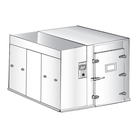
Section 1 Installation Requirements General Description The Getinge 7800A Series Floor Mounted Cart and Utensil Washer is a fully automatic, large capacity, hydro-spray washer that is used to clean and dry case carts, stands, utensils, containers, tote boxes, and similar bulk items. -
Page 10: Model Identification
Record the model type and serial number (S/N) from the rating plate. TYPE: _________________________________ SERIAL NO: ____________________________ Include the model type and serial number when communicating with Getinge, USA. Figure 1–2. Rating Plate Location Utilities and Specifications Utility requirements and specifications are included on sheet 2 of the appropriate rough-in drawing (pit mounted or floor mounted version). -
Page 11: Installation Advisory
Where applicable, installers should refer to specifications contained in the product information documents, such as Assembly drawings, that have been forwarded to local Getinge USA product support personnel. Rough-in drawings can be found in “Rough-In Drawings” on page 3-1. Washer Options There are a number of options that may be included with your washer. -
Page 12: Vented Vs. Non-Vented
Installation Requirements Vented vs. Non-vented A vented washer has an automatic damper that connects directly to the ventilation system of your facility. A non-vented washer has a condenser (with associated electric and plumbing connections) mounted on the top of the washer to remove moisture from the air that is exhausted from the washer. -
Page 13: Tools And Materials Required
7800A Series Floor Mounted Cart and Utensil Washer Tools and Materials Required The following tables list the specific tools and materials required at the installation site. Items marked with an asterisk * are supplied by Getinge USA. Table 1–1. Tools Required... - Page 14 Installation Requirements Material Quantity 1" x 4" x 6" Wood Block 2" x 4" x 52" Wood Block Four rigid 3/4" x 60" long pipes are recommended for use if a floor mounted washer is to be assembled out-of-position, then moved to its intended operational site.
-
Page 15: Section 2 Installation
Section 2 Installation Assemble the Washer Structure This section contains procedures for assembling the basic structure of the washer compartment. Refer to the following sections. • “Install the Base/Sump Assembly” on page 2-1 • “Position the Mechanical Core” on page 2-3 •... - Page 16 Installation Failure to critically level the base will result in the misalignment of mounting holes and will make assembly of the washer panels difficult. CAUTION If seismic anchoring is required, two 2 1/2" flanges (with anchor bolt holes) must be bolted to the bottom frame of the base (one flange on each end of the washer).
- Page 17 7800A Series Floor Mounted Cart and Utensil Washer Position the Mechanical Objective Core Position the mechanical core in its approximate location on the side of the washer. Installation Refer to Figure 2–3. Mechanical Core. Figure 2–3. Mechanical Core MOUNTING BRACKET...
- Page 18 Installation 1. Using a fork lift, move the mechanical core into place on the service side of the washer, approximately one inch away from where the washer side walls will be. If your washer has a left-hand service area, one of the adjustable legs rests NOTE on the pad on the right side of the sump box.
-
Page 19: Assemble The Washer Panels
7800A Series Floor Mounted Cart and Utensil Washer Assemble the Washer Panels Objective Assemble the door, side, and top panels. Install the required number of interior side panel seam cover strips. The 7800A washers have five or six side panels and three top panels. The middle panel on the front (service) side, the end panels on the rear, and the top panels at each end are common for all three washer lengths. - Page 20 Installation 1. Attach the load end door panels to the base. There are two vertical panels, each with three mounting holes at the top to attach to the horizontal panel. a. Position a vertical panel and use a C-clamp to hold the panel in place temporarily.
- Page 21 7800A Series Floor Mounted Cart and Utensil Washer Figure 2–5. Side Panels THRU BOLTS (5 EACH SIDE) Skip step 3 below if the washer does not have middle panel sections. NOTE 3. Attach the rear middle side panel to the base and to the load end panel.
- Page 22 Installation 4. Attach the unload end rear side panel to the base and to the middle side panels. a. Remove the pipe clamps. b. Position the unload end rear side panel. Extend the five thru bolts to stabilize and align this panels with the previously erected panels.
- Page 23 7800A Series Floor Mounted Cart and Utensil Washer 7. Attach the load end top panel to the door panel and to the load end side panels. a. Position the load end top panel. b. Secure the top panel to the door and load end side panels with 1/4-20 fasteners (1-3/4"...
- Page 24 Installation 10. Secure the mechanical core to the side panels. a. Use the adjustable legs to align the holes in the mounting bracket and in the dryer duct flange with the corresponding holes in the side of the washer. b. From inside the washer, apply silicone sealant to the surface of the dryer flange.
-
Page 25: Channel Fillers And Threshold Assemblies
7800A Series Floor Mounted Cart and Utensil Washer Channel Fillers and Objective Threshold Assemblies Install a channel filler on the floor just inside each washer door. Install a threshold assembly just outside each washer door. Installation Refer to Figure 2–6. Channel Fillers and Threshold Assemblies. -
Page 26: Door Assembly
Installation Door Assembly Objective Attach hardware to the doors and related door panels. Install the load and unload end doors on the washer. Plumb and square both door openings. Installation Refer to Figure 2–7. Door Assembly. Figure 2–7. Door Assembly DOOR LATCH DOOR LATCH RETAINERS... - Page 27 7800A Series Floor Mounted Cart and Utensil Washer 1. Attach the following items to each door panel: a. Attach three hinge mounts using 1/4-20 fasteners (nine 1" phillips head screws). b. Attach two door latch retainers, two door latch shims, and two spacers using 5/16-18 fasteners (four each 2"...
- Page 28 Installation Install Components on the Outside of the Washer This section provides instructions for installing equipment on the outside of the washer. The procedures are presented in a recommended order (some larger components are easier if they are done earlier, for example). Refer to the following sections.
-
Page 29: Return Pump
7800A Series Floor Mounted Cart and Utensil Washer Return Pump Objective Install the return pump. Installation The return pump may be shipped from the factory already installed in the NOTE sump. Refer to Figure 2–8. Return Pump. Figure 2–8. Return Pump RETURN PUMP 1. -
Page 30: Washer Light Assembly
Installation Washer Light Assembly Objective Install the interior light in the cutout located on the front (service side) wall. Installation 1. Align the holes in the light assembly with the holes surrounding the cutout in the front panel. 2. Secure the light assembly to the front panel with eight #10- 32 fasteners (phillips head screws and flat washers) as shown in Figure 2–9. -
Page 31: Spray Manifold Drive Motor
7800A Series Floor Mounted Cart and Utensil Washer Spray Manifold Drive Motor Objective Assemble the spray manifold drive’s flange bearing and the spray manifold drive motor. Installation Refer to Figure 2–10. Spray Manifold Drive Flange Bearing. Figure 2–10. Spray Manifold Drive Flange Bearing... -
Page 32: Control Box
Installation Control Box Objective Attach the control box to the load end side panel. Installation Refer to Figure 2–12. Control Box. Figure 2–12. Control Box 1/4-20 FASTENERS (4 PLACES) 1. Remove the pins from the door hinges and set the door aside. -
Page 33: Dispenser Float Switch Junction Box, Detergent Dispenser, And Rinse Aid Dispenser
7800A Series Floor Mounted Cart and Utensil Washer Dispenser Float Switch Objective Junction Box, Detergent Dispenser, and Rinse Aid Install the junction box for the detergent and rinse aid dispenser float switches on the front (service side) panel at the load end of the washer. - Page 34 Installation 3. Install the detergent dispenser. a. Align the mounting holes in the back plate with the set of threaded holes in the panel. b. Use two #10-32 fasteners to secure the dispenser in place. 2–20...
-
Page 35: Emergency Stop Switch
7800A Series Floor Mounted Cart and Utensil Washer Emergency Stop Switch Objective Attach the emergency stop switch to the side panel of the washer. The switch is mounted at the load end of the washer, under the control box. Installation Refer to Figure 2–14. -
Page 36: Unload End Indicator Panel Box
Installation Unload End Indicator Panel Objective Mount the indicator panel box on the unload end of the washer. Installation Refer to Figure 2–15. Unload End Indicator Panel Box. Figure 2–15. Unload End Indicator Panel Box 1. Remove the face plate of the box. 2. -
Page 37: Door Proximity Switches
7800A Series Floor Mounted Cart and Utensil Washer Door Proximity Switches Objective Install a proximity switch assembly on both the load and the unload end door panels. The sensors are interchangeable. Installation Refer to Figure 2–16. Door Proximity Switches. Figure 2–16. Door Proximity Switches... -
Page 38: Install Components On Top Of The Washer
Installation Install Components on Top of the Washer There are a number of components that are installed on the top panels of the washer. Although there is no specific order in which the components should be installed, the list below presents the items in a recommended order. -
Page 39: Power Floor Tilt Pulley System
7800A Series Floor Mounted Cart and Utensil Washer Power Floor Tilt Pulley Objective System Install the power tilt floor pulley system. The top panels have 1/4-20 threaded holes to mount the system’s three components. The actuator assembly is installed across the middle roof panel with the pulley end along the non-service side of the washer. - Page 40 Installation Figure 2–18. Pulley Mount PULLEY MOUNT 1/4-20 FASTENERS b. Secure the load end pulley mount to the corner of the load end top panel with 1/4-20 fasteners (two each 1/2" hex head screws, lock washers, and flat washers). Secure the unload end pulley mount to the corner of the unload end top panel with 1/4-20 fasteners (two each 1/2"...
-
Page 41: Transformer
7800A Series Floor Mounted Cart and Utensil Washer Transformer Objective If applicable, install the transformer to the top of the washer. The specific transformer used with your washer depends on the house-supplied voltage. Installation Refer to Figure 2–20. Transformer. Figure 2–20. Transformer... -
Page 42: Exhaust Assembly
Installation Exhaust Assembly Objective Mount the exhaust assembly on the roof panel at the load end of the washer. The exhaust assembly is installed on vented units only. Installation Figure 2–21. Exhaust Assembly DAMPER MOTOR #10-32 FASTENERS (6 PLACES) Silicone primer (orange) is extremely flammable, harmful if swallowed or inhaled, and harmful to eyes or skin. -
Page 43: Intake Assembly
7800A Series Floor Mounted Cart and Utensil Washer Intake Assembly Objective Mount the intake assembly on the top of the washer above the unload end door. Installation Refer to Figure 2–22. Intake Assembly. Figure 2–22. Intake Assembly #10-32 FASTENERS (4 PLACES) Silicone primer (orange) is extremely flammable, harmful if swallowed or inhaled, and harmful to eyes or skin. -
Page 44: Plumbing
Installation Plumbing The washer plumbing is designed with a number of quick-disconnect joints that enable service personnel to isolate problems and to replace components easily. When a washer is disassembled at the factory for shipment to a customer, plumbing sections are removed for efficient packing and quick assembly at the installation site. - Page 45 7800A Series Floor Mounted Cart and Utensil Washer Figure 2–23. Drain Box Assembly TANK DRAIN DRAIN TEMPERING NON-VENTED CONDENSER CONDENSER (OPTION) TANK OVERFLOW SUMP DRAIN SUMP OVERFLOW Refer to Figure 2–23. Drain Box Assembly for steps 6 through 11 below.
-
Page 46: Electrical Wiring
Installation Electrical Wiring Objective Make all required electrical wire connections between the electrical components and the control box. Installation 1. Route all component electrical cables, including thermocouple cables, from the control box to the appropriate electrical component. Refer to Table 2–2 for the routings. 2. - Page 47 7800A Series Floor Mounted Cart and Utensil Washer Table 2–2. Control Box Cable Connections Jack Cable P/N Cable Label Destination J1-J2 Not used. 61301604989 P3 – 1PX Load End Door Proximity Switch 1PX 61301604989 P4 – 2PX Unload End Door Proximity...
- Page 48 Installation Jack Cable P/N Cable Label Destination 61301604134 P36 – 1MTR Wash Pump 1MTR 61301603987 P37 – 2MTR Dryer Blower Motor 2MTR Not used. 61301603988 P39 – 4MTR Manifold Drive Motor 4MTR P40 – T Transformer T J41– Not used. 61301603976 P50 –...
-
Page 49: Install Components On The Inside Of The Washer
7800A Series Floor Mounted Cart and Utensil Washer Install Components on the Inside of the Washer This section provides instructions for installing equipment on the inside of the washer. The procedures are presented in a recommended order. Refer to the following sections. -
Page 50: Chain Drive Assembly
Installation Chain Drive Assembly Objective Install the drive shaft, drive chains, and push rod that comprise the chain drive assembly. Installation Refer to Figure 2–26. Chain Drive Assembly. Figure 2–26. Chain Drive Assembly 1. Insert the drive shaft key into the keyway in the spray manifold drive motor that you installed previously. - Page 51 7800A Series Floor Mounted Cart and Utensil Washer 7. Rotate the idler end of the shaft until its sprocket key is in alignment with the sprocket key at the shaft’s motor end. 8. Secure the shaft ends to the shaft coupling with two #10-32 bolts and jam nuts.
-
Page 52: Spray Manifold Supports And Spray Manifolds
Installation Spray Manifold Supports and Objective Spray Manifolds Install the two spray manifold supports, one on either side of the washer compartment, and then install the two spray manifolds. Installation Refer to Figure 2–27. Spray Manifold Support. Figure 2–27. Spray Manifold Support 1. - Page 53 7800A Series Floor Mounted Cart and Utensil Washer 3. Attach 1/4-20 bolts and nylock nuts to the captive brackets to ensure the ends of the spray manifold supports remain in place. Figure 2–28. Spray Manifold Assembly 4. Attach the rinse and the wash hose connectors to the inlet ports in the middle side panel.
- Page 54 Installation 7. Use 5/16-18 fasteners to connect the manifolds at the bottom with two connector bars. Use two sets of fasteners at the end of each connector bar. Figure 2–29. Wash and Rinse Manifold Hoses WASH MANIFOLD HOSES RINSE MANIFOLD HOSES 8.
-
Page 55: Manifold Cover, Manifold Guard Tubes, Wash Cart Tubes
7800A Series Floor Mounted Cart and Utensil Washer Manifold Cover, Manifold Objective Guard Tubes, Wash Cart Tubes Install the following components inside the washer: • Manifold cover • Four manifold guard tubes • Two wash cart guide tubes Installation Refer to Figure 2–30. Manifold Cover, Manifold Guard Tubes, Wash Cart Guide Tubes. - Page 56 Installation 2. Attach the four manifold guard tubes to the captive brackets welded to the load and unload end door panels. a. Place a 1/4-20 bolt through the manifold guard tube brackets on each end of the washer at the appropriate level and secure with a lock nut.
-
Page 57: Emergency Stop Switch Cable
7800A Series Floor Mounted Cart and Utensil Washer Emergency Stop Switch Objective Cable Install the emergency stop cable. The cable runs along the service side of the washer, passes through the side panel, and connects to the emergency stop switch on the service side of the washer. -
Page 58: Final Installation Tasks
Installation Final Installation Tasks This section provides instructions for completing the installation of the washer. Refer to the following sections. • “Final Door Assembly” on page 2-45 • “Dispenser Tubing” on page 2-46 • “Barrier Flanges” on page 2-48 • “Pit Covers” on page 2-49 •... -
Page 59: Final Door Assembly
7800A Series Floor Mounted Cart and Utensil Washer Final Door Assembly Objective Hang the load and unload doors back on their hinges. Installation Refer to Figure 2–33. Door Assembly. Figure 2–33. Door Assembly A washer door is heavy and awkward to handle. Take care to WARNING avoid crushing or strain injuries. -
Page 60: Dispenser Tubing
Installation Dispenser Tubing Objective Connect the detergent and rinse aid dispenser pump tubing. Installation 1. Connect the detergent tubing. a. Place the detergent float switch assembly (see Figure 2–34) in the detergent supply container. Figure 2–34. Detergent/Rinse Aid Float Switch b. - Page 61 7800A Series Floor Mounted Cart and Utensil Washer 2. Connect the rinse aid tubing. a. Place the rinse aid float switch assembly in the rinse aid supply container. b. Connect the supply tubing from the float switch assembly to the bottom plastic compression fitting on the rinse aid pump (Figure 2–36).
-
Page 62: Barrier Flanges
Installation Barrier Flanges Objective Attach the barrier flanges to the load and unload ends of the washer. The following instructions apply to units with structural walls situated at both the load and unload ends. Units with only one wall (generally at the unload end) receive a service area enclosure and an unload end top barrier flange. -
Page 63: Pit Covers
7800A Series Floor Mounted Cart and Utensil Washer 2. Secure the load and unload end side barrier flanges to the attachment angles with #10-32 fasteners. The interior edge of a flange seats between an angle and the side panel. 3. Attach the top barrier flanges. -
Page 64: Service Area Enclosure (Option)
Installation Service Area Enclosure Objective (Option) Assemble the service area enclosure. The service area enclosure is usually installed on units that do not have a structural wall at either the load or unload end. Installation Refer to Figure 2–39. Service Area Enclosure. Figure 2–39. -
Page 65: Ramps
7800A Series Floor Mounted Cart and Utensil Washer 4. Position the access panel divider on the mounting base frame. The upper end of the divider has two #10-32 threaded holes and the lower end has two 1/4" diameter holes. Secure the bottom of the divider to the frame with two #10-32 fasteners. -
Page 66: Exhaust Connection
Installation Exhaust Connection This procedure applies only to vented washers. Install a dedicated, corrosion-proof, watertight duct (800 CFM, negative 1/4" static pressure) from the 6 1/2" x 10" flanged exhaust assembly (Figure 2–21 on page 2–28) to the building’s exhaust system. The duct assembly should be sloped toward the washer. -
Page 67: Concluding Tasks
5. Perform the steps in the Installation Checkout Procedure included with your washer. Complete the SCR and return both to Getinge USA service headquarters. At this point, installation is complete. You must contact Getinge USA NOTE personnel to make mechanical adjustments and electrical performance tests before the equipment is operated. - Page 68 Installation 2–54...
-
Page 69: Section 3 Rough-In Drawings
Section 3 Rough-In Drawings Rough-in drawings for the pit mounted and floor mounted versions of the 7800A washer are included in the following pages. 61301604981 3–1... - Page 70 Rough-In Drawings Figure 3–1. 7800A Washer (HS4099, sheet 1 of 7) 3–2...
- Page 71 7800A Series Floor Mounted Cart and Utensil Washer Figure 3–1. 7800A Washer (HS4099, sheet 2 of 7) 61301604981 3–3...
- Page 72 Rough-In Drawings Figure 3–1. 7800A Washer (HS4099, sheet 3 of 7) 3–4...
- Page 73 7800A Series Floor Mounted Cart and Utensil Washer Figure 3–1. 7800A Washer (HS4099, sheet 4 of 7) 61301604981 3–5...
- Page 74 Rough-In Drawings Figure 3–1. 7800A Washer (HS4099, sheet 5 of 7) 3–6...
- Page 75 7800A Series Floor Mounted Cart and Utensil Washer Figure 3–1. 7800A Washer (HS4099, sheet 6 of 7) 61301604981 3–7...
- Page 76 Rough-In Drawings Figure 3–1. 7800A Washer (HS4099, sheet 7 of 7) 3–8...
- Page 77 Section 4 Seismic Anchoring Drawings Seismic anchoring drawings for the 7800A washer are included in the following pages. 61301604981 4–1...
- Page 78 Seismic Anchoring Drawings Figure 4–1. 7800A Washer (700488, sheet 1 of 12) 5/16/03 A 121179 4–2...
- Page 79 7800A Series Floor Mounted Cart and Utensil Washer Figure 4–1. 7800A Washer (700488, sheet 2 of 12) A 121179 5/16/03 61301604981 4–3...
- Page 80 Seismic Anchoring Drawings Figure 4–1. 7800A Washer (700488, sheet 3 of 12) A 121179 5/16/03 4–4...
- Page 81 7800A Series Floor Mounted Cart and Utensil Washer Figure 4–1. 7800A Washer (700488, sheet 4 of 12) A 121179 61301604981 4–5...
- Page 82 Seismic Anchoring Drawings Figure 4–1. 7800A Washer (700488, sheet 5 of 12) A 121179 5/16/03 4–6...
- Page 83 7800A Series Floor Mounted Cart and Utensil Washer Figure 4–1. 7800A Washer (700488, sheet 6 of 12) A 121179 5/16/03 61301604981 4–7...
- Page 84 Seismic Anchoring Drawings Figure 4–1. 7800A Washer (700488, sheet 7 of 12 A 121179 5/16/03 4–8...
- Page 85 7800A Series Floor Mounted Cart and Utensil Washer Figure 4–1. 7800A Washer (700488, sheet 8 of 12) A 121179 5/16/03 61301604981 4–9...
- Page 86 Seismic Anchoring Drawings 7800A Washer (700488, sheet 9 of 12) A 121179 5/16/03 4–10...
- Page 87 7800A Series Floor Mounted Cart and Utensil Washer Figure 4–1. 7800A Washer (700488, sheet 10 of 12) 5/16/03 A 121179 61301604981 4–11...
- Page 88 Seismic Anchoring Drawings Figure 4–1. 7800A Washer (700488, sheet 11 of 12) A 121179 5/16/03 4–12...
- Page 89 7800A Series Floor Mounted Cart and Utensil Washer Figure 4–1. 7800A Washer (700488, sheet 12 of 12) A 121179 5/16/03 61301604981 4–13...
- Page 90 Seismic Anchoring Drawings 4–14...
- Page 91 Index Float Switch Junction Box 2–19 Floor Grates 2–2 Actuator Assembly 2–25 Floor Mount Option 1–3 Floor Tilt Pulley System 2–25 Barrier Flanges 2–48 Base/Sump Assembly 2–1 General Description 1–1 Guard Tubes 2–41 Cables, Emergency Stop Switch 2–43 Chain Drive Assembly 2–36 Hinge Mounts 2–13 Channel Fillers 2–11 Control Box 2–18...
- Page 92 Index 2–41 Pit Covers 2–49 Plumbing System Connections 2–52 Options 1–3 Power Floor Tilt Pulley System 2–25 Ramps 2–51 Return Pump 2–15 Service Area Enclosure 2–50 Spray Manifold Drive Motor 2–17 Panels 2–5 Spray Manifold Supports and Manifold Assembly 2–38 Pit Covers 2–49 Threshold Assemblies 2–11 Transformer 2–27...
- Page 93 7800A Series Floor Mounted Cart and Utensil Washer Utilities and Specifications 1–2 Tension Idlers 2–35 Threshold Assemblies 2–11 Vented Option 1–4 Tools and Materials Required 1–5 Track/Frame Assembly 2–2 Transformer 2–27 Wash Cart Tubes 2–41 Tubing, Dispenser 2–46 Washer Options 1–3 Washer Panels 2–5...
- Page 94 Index I–4...
- Page 96 Getinge USA, Inc. 1777 East Henrietta Road Telephone (800) 950–9912 Rochester, New York 14623–3133 USA Facsimile (800) 950–2570...
Need help?
Do you have a question about the 7800A Series and is the answer not in the manual?
Questions and answers