Table of Contents
Advertisement
Quick Links
Advertisement
Table of Contents

Subscribe to Our Youtube Channel
Related Manuals for Gossen MetraWatt M234D


Summary of Contents for Gossen MetraWatt M234D
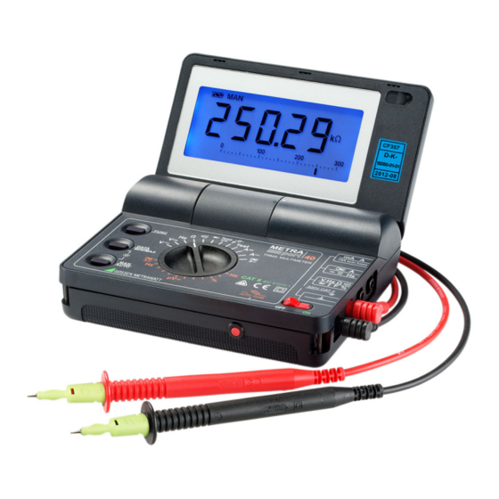
- Page 1 Operating Instructions METRAport40S 3-349-412-02 Digital Multimeter 8/12.18...
- Page 2 Control Elements 1 LCD 2 Battery compartment cover 3 mA, A connector jack for direct measurement of current to “max. 10 A” A connector jack for current clamp measurement to “max. 30 V” 5 Connector jack for all measuring ranges except current measuring ranges 6 “”connector jack for all measuring ranges 7 OFF/ON: ON/OFF switch 8 Resettable miniature circuit breaker (AUTO FUSE)
- Page 3 Digital Display Symbols 1 Continuous operation 2 Battery voltage display 3 Digital display with indication of decimal place and polarity 4 Manual measuring range selection 5 Display memory, “freeze measured value” 6 MIN-MAX storage 7 ZERO: zero balancing active 8 Selected current type, DC or DCAC ( ) 9 USB Interface display (when communication is active ...
-
Page 4: Table Of Contents
Contents......................... Page Safety Features and Precautions ................5 Initial Start-Up ......................7 Selecting Measuring Functions and Measuring Ranges .........8 Automatic Measuring Range Selection ................8 Manual Measuring Range Selection – MAN/AUTO Key ..........8 Quick Measurements ....................9 Display (LCD) ......................9 Display Illumination ....................9 Digital Display ......................9 Analog Display ......................9 Measured Value Storage –... -
Page 5: Safety Features And Precautions
Safety Features and Precautions You have selected an instrument which provides you with a high level of safety. This instrument fulfills the requirements of the applicable EU guidelines and national regulations. We confirm this with the CE marking. The relevant declara- tion of conformity can be obtained from GMC-I Messtechnik GmbH. - Page 6 • Be absolutely certain that the measuring ranges are not overloaded beyond their allowable capacities. Limit values can be found in the “Measuring Ranges” table in chapter 15, “Characteristic Values”. Meaning of symbols on the instrument Warning concerning a point of danger (Attention: observe documentation!) Earth Continuous doubled or reinforced insulation...
-
Page 7: Initial Start-Up
Initial Start-Up Installing Batteries Attention! Disconnect the instrument from the measuring circuit at all poles before opening the battery compartment! ➭ Fold the instrument closed. ➭ Insert a coin or a similar object into the slot between the housing and the battery compartment cover and press down until the battery compartment cover snaps open. -
Page 8: Selecting Measuring Functions And Measuring Ranges
Disabling Automatic Shutdown The instrument can be switched to “CONTINUOUS ON”. ➭ Press the FUNC key while switching the instrument on with the toggle switch until an acoustic signal is generated. The “CONTINUOUS ON” function is indicated at the display with the symbol. -
Page 9: Quick Measurements
Quick Measurements If you wish to perform quicker measurements than those possible with the auto- matic measuring range selection function, make sure to establish the appropriate measuring range: • by manual measuring range selection, i. e. by selecting the measuring range with the best resolution, see chapter 3.2. -
Page 10: Measured Value Storage - Data / Min-Max Key
Measured Value Storage – DATA / MIN-MAX Key DATA (hold / compare) Measured values can be automatically frozen at the display with the DATA (hold) function. This is especially useful when full attention is required for contacting the measuring point. After the measured value has been applied to the multimeter and the “condition”... -
Page 11: Storage Of Minimum And Maximum Values "Min/Max" With Time Stamp
Storage of Minimum and Maximum Values “MIN/MAX” with Time Stamp Minimum and maximum measured values which occur at the input of the mea- suring instrument after the MIN/MAX function has been activated can be saved to memory. The most important application for this function is the determination of minimum and maximum values during long-term observation of measured quantities (same function as the slave pointer at an analog display). -
Page 12: Voltage And Frequency Measurement
Voltage and Frequency Measurement ➭ Set the rotary switch to either V (TRMS) or V , depending upon the voltage to be measured. ➭ You can switch back and forth between voltage and frequency measurement in the V switch position by pressing the FUNC key. Connect the measurement cables as shown. -
Page 13: Low-Voltage Measurement
Low-Voltage Measurement The instrument is equipped with a special 30 mV measuring range for measuring voltage drop at fuses which is distinguished by high resolution (10 V) with a low input resistance of 50 k. ➭ Set the rotary switch to “Temp RTD”. ➭... -
Page 14: Current Measurement With Current (Clamp) Sensors With Voltage Output
• Eliminate the cause of overload after the fuse or breaker is tripped before placing the instrument back into service! Attention! If the secondary side of the current transformer with voltage output remains open during operation, e.g. if cables are defective or have not been connected, or due to a blown device fuse or incorrect connection, dangerous voltages may occur at the terminals. -
Page 15: Rpm Measurement At Combustion Engines
Please observe the specified operating conditions per IEC/EN 61010-2-32 regarding measurement category, etc. for the applied current sensor. Additional error caused by the current sensor must be taken into consideration. max. measuring range Current sensor Measuring ranges transformer ratio available in the multimeter A~ * V / A 0 ... -
Page 16: Resistance Measurement
Resistance Measurement Set the rotary switch to the ➭ position. Overload is indicated if no device under test has been connected: “0. L M”. ➭ Before connecting the device under test, make sure that it is voltage- free. Interference voltages distort measurement results! Perform a voltage test first if required. -
Page 17: Diode Testing
Diode Testing ➭ Turn the selector switch to the position. Overload is indicated if no device under test has been connected: “. 0 L V”. ➭ Make sure that the device under test is voltage-free. Interference voltages distort measurement results! Perform a voltage test first if required. ➭... -
Page 18: Capacitance Measurment
Capacitance Measurment ➭ Make sure that the device under test is voltage-free. Interference voltages distort measurement results! ➭ Turn the rotary switch to the “F” position. – ➭ Connect the (discharged!) device under test to the and V jacks with the measurement cables. -
Page 19: Temperature Measurement With Pt100 And Pt1000
Temperature Measurement with Pt100 and Pt1000 ➭ Set the rotary switch to “Temp RTD”. ➭ Connect the P sensor to the and V jacks. The instrument automatically recognizes type of connected sensor (Pt100 or Pt1000), and displays measured temperature in the selected unit of measure. -
Page 20: Characteristic Values
Characteristic Values Resolution at MUL Input Impedance Measuring Measuring Range Function 30 000 3 000 V DC 10 V 30 mV 50 k — 10 V 300 mV > 11 M 11 M // < 50 pF 100 V 11 M 11 M... - Page 21 Intrinsic Uncertainty under Reference Conditions Overload Capacity Measuring ( % rdg. + d) ( % rdg. + d) Range 2) 6) Value Duration 30 mV 1 + 5 — 600 V 4) 7 300 mV 0.2 + 5 1 + 30 (DC) 0.2 + 3...
- Page 22 Influence Quantities and Influence Error Influence Sphere Measured Quantity / Influence Error ( % + d) / 10 K Quantity of Influence Measuring Range 0.2 + 10 0.4 + 10 300 A 300 mA 0.5 + 10 0 C 3 A / 10 A 1 + 10 +21 C...
- Page 23 Influence Sphere of Measured Quantity / Influence Error Quantity Influence Measuring Range 1 2 1% rdg. Crest > 2 4 5% rdg. factor V ~, A ~ > 4 5 7% rdg. Allowable crest factor CF for the periodic quantity to be measured Measured depends upon the displayed value:...
- Page 24 Response Time (after manual range selection) Measured Quantity / Digital Display Measured Quantity Measuring Range Response Time Jump Function , V ~, from 0 to 80% 1.5 s of the measuring range upper limit , A ~ 30 3 M 30 M...
- Page 25 Service Life with alkaline-manganese batteries: approx. 100 hours Battery Test Battery capacity display with battery symbol in 4 segments: “ ” Battery Saving Circuit The instrument is switched off automatically – if the measured value remains unchanged for a period of approximately 10 minutes, and if none of the control elements are operated during this period.
-
Page 26: Maintenance
Maintenance Attention! Disconnect the instrument from the measuring circuit before opening to replace batteries or fuses! 16.1 Batteries Make sure that no battery leakage has occurred before placing your instrument into service for the first time, or after long periods of storage. Repeat this inspection on a regular basis thereafter. -
Page 27: Housing / Opening Of Equipment / Repair
Attention! Inspect the measuring circuit and eliminate the cause of overload before activating the reset button at the miniature circuit breaker. The fuse link connected in series to the auto-fuse may only be replaced by authorized service personnel. 16.3 Housing / Opening of Equipment / Repair No special maintenance is required for the housing. -
Page 28: Repair And Replacement Parts Service Calibration Center* And Rental Instrument Service
Repair and Replacement Parts Service Calibration Center* and Rental Instrument Service When you need service, please contact: GMC-I Service GmbH Service-Center Beuthener Straße 41 90471 Nürnberg • Germany Phone +49 911 817718-0 +49 911 817718-253 E-Mail service@gossenmetrawatt.com www.gmci-service.com This address is only valid in Germany. Please contact our representatives or subsidiaries for service in other countries.
Need help?
Do you have a question about the M234D and is the answer not in the manual?
Questions and answers