Table of Contents
Advertisement
Quick Links
Advertisement
Table of Contents

Related Manuals for Mark-10 TT02 Series


Summary of Contents for Mark-10 TT02 Series
- Page 1 TT02 Series TORQUE TOOL TESTERS User’s Guide...
-
Page 2: Table Of Contents
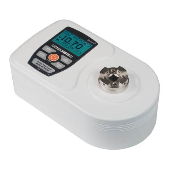
Series TT02 Digital Torque Tool Testers User’s Guide Thank you… Thank you for purchasing a Mark-10 Series TT02 digital torque tool tester, designed to measure the torque produced by manual, electric, and pneumatic torque tools. With proper usage, we are confident that you will get many years of great service with this product. -
Page 3: Overview
User’s Guide ® ® Download at: www.mark-10.com/resources 1.2 Safety / Proper Usage Caution! Note the torque tester’s capacity before use and ensure that the capacity is not exceeded. Producing a torque greater than 150% of the tester’s capacity can damage the internal sensor. An overload can occur whether the tester is powered on or off. -
Page 4: Power
Series TT02 Digital Torque Tool Testers User’s Guide 2 POWER The TT02 is powered either by an 8.4V NiMH rechargeable battery or by an AC adapter. Since these batteries are subject to self discharge, it may be necessary to recharge the unit after a prolonged period of storage. -
Page 5: Setup
2. Install the USB driver before physically connecting the tester to a PC with the USB cable. Download the USB driver at: www.mark-10.com/resources Further instructions for configuring and using the tester’s outputs are provided in the Communications and Outputs section. - Page 6 Series TT02 Digital Torque Tool Testers User’s Guide 3.3 Proper alignment Align the tool axially with respect to the square drive in the receptacle. Side loading or off-center loading may produce erroneous readings, and can damage the instrument. Note: It is normal to detect a small amount of mechanical play in the receptacle. 3.4 Mounting to a bench The tester can be mounted to a bench for horizontal or other orientations using the optional bench mounting kit, as shown below:...
-
Page 7: Home Screen And Controls
Series TT02 Digital Torque Tool Testers User’s Guide 4 HOME SCREEN AND CONTROLS 4.1 Home Screen Name Description Measurement – indicates clockwise direction direction – indicates counter-clockwise direction indicator These indicators are used throughout the display and menu. The maximum measured clockwise and counter-clockwise readings. 2A and 2B refer to First and Second peaks, respectively, when the tester is in Peaks First / Second Peak mode (see First/Second Peak section for details). - Page 8 Series TT02 Digital Torque Tool Testers User’s Guide On/Off Break Detection section for details. The current measurement mode. Abbreviations are as follows: RT – Real Time PCW – Peak Clockwise Mode PCCW – Peak Counter-clockwise 2PK – First / Second Peak BRK –...
-
Page 9: Operating Modes
Series TT02 Digital Torque Tool Testers User’s Guide item, or press ESCAPE to revert back to the sub-menu item without saving. Press ESCAPE to revert one step back in the menu hierarchy until back into normal operating mode. Refer to the following sections for details about setting up particular functions and parameters. 5 OPERATING MODES Caution! In any operating mode, if the capacity of the instrument has been exceeded by more than 110%,... -
Page 10: Changing The Units
Series TT02 Digital Torque Tool Testers User’s Guide 6 CHANGING THE UNITS The TT02 can display five different measurement units. To change the unit, select Units from the menu. The display will list the available units, as follows: UNITS ozFin lbFin kgFcm The tester will always power on with the unit selected in this sub-menu. -
Page 11: Set Points
Series TT02 Digital Torque Tool Testers User’s Guide 8 SET POINTS 8.1 General Information Set points are useful for tolerance checking (pass/fail) and triggering an external device in process control applications. Two limits, high and low, are programmed in the tester, and the primary reading is compared to these limits. -
Page 12: Break Detection
Series TT02 Digital Torque Tool Testers User’s Guide 8.2.1 Set Point Outputs Schematic Diagram 9 BREAK DETECTION The break detection function identifies when the tool has clicked, slipped, or stopped – or applications in which the torque value has reached a peak, then dropped. Upon detection of the break, the tester can perform several automatic functions, as follows: 1. - Page 13 Series TT02 Digital Torque Tool Testers User’s Guide Automatically zeroes the display following data transmission and/or storage. A Auto Zero time delay may be configured in Break Detection Settings. Refer to the next sub-section for details. If tones are enabled, a tone will sound when the output, storage, and zero functions have occurred. 9.2 Break Settings Select Break Settings from the Break Detection menu to configure the settings.
-
Page 14: First / Second Peak
Series TT02 Digital Torque Tool Testers User’s Guide 10 FIRST / SECOND PEAK This function is designed to accurately capture the true peak torque a tool generates at slip or click (first peak), before a mechanical stop causes an artificial spike in torque (second peak). 10.1 Configuration Several functions can be triggered automatically upon first and second peaks: 1. - Page 15 Series TT02 Digital Torque Tool Testers User’s Guide 10.2 Settings The display appears as follows: PEAK SETTINGS Thresh. 1: % Drop 1: 10 % Thresh. 2: % Drop 2: 10 % Auto Zero Delay 3 sec. Threshold 1 Sets the percentage of full scale at which the first/second peak detection feature becomes active.
-
Page 16: Data Memory And Statistics
Series TT02 Digital Torque Tool Testers User’s Guide 10.3 Auto Output Settings Select the output type. Select RS-232/USB and/or Mitutoyo outputs, and select First and/or Second peaks. The display appears as follows: AUTO OUTPUT SETTINGS RS232/USB Output Mitutoyo Output First Peak Second Peak 11 DATA MEMORY AND STATISTICS Series TT02 testers have storage capacity of 1,000 data points. - Page 17 Press ENTER to output data to an external device. The display will show, “SENDING DATA…”, then “DATA SENT”. If there was a problem with communication, the display will show, “DATA NOT SENT”. Saved data can be downloaded by some Mark-10 data collection programs. Refer to their respective user’s guides for details.
-
Page 18: Communications And Outputs
Series TT02 Digital Torque Tool Testers User’s Guide 12 COMMUNICATIONS AND OUTPUTS Communication with the TT02 tester is achieved through the micro USB or 15-pin serial ports located in the rear of the housing, as shown in the illustration in the Power section. Communication is possible only when the tester is in the main operating screen (i.e. - Page 19 Series TT02 Digital Torque Tool Testers User’s Guide Individual data points may be transmitted by pressing DATA. Series TT02 testers may also be controlled by an external device through the RS-232 or USB channels. The following is a list of supported commands and their explanations.
- Page 20 Series TT02 Digital Torque Tool Testers User’s Guide 12.4 DATA Key Settings To configure the functions of the DATA key, select DATA Key from the menu. The display appears as follows: DATA KEY RS232/USB Output Mitutoyo Output Memory Storage RS232/USB Output Outputs data via the serial and USB ports Mitutoyo Output Outputs data via Mitutoyo (Digimatic) through the serial port...
- Page 21 Series TT02 Digital Torque Tool Testers User’s Guide 12.5 I/O Connector Pin Diagram (DB-15HD female) Pin No. Description Input / Output Signal Ground Counter-clockwise Overload Output RS-232 Receive Input RS-232 Transmit Output +12V DC Input / Output Analog Output Output Clockwise Overload Output Mitutoyo Clock...
-
Page 22: Calibration
Series TT02 Digital Torque Tool Testers User’s Guide 13 CALIBRATION 13.1 Initial Physical Setup The TT02 should be mounted to a fixture rugged enough to withstand a load equal to the full capacity of the tester. Suitable certified calibration equipment is required, and caution should be taken while handling such equipment. - Page 23 Series TT02 Digital Torque Tool Testers User’s Guide CALIBRATION OFFSET Place torque sensor horizontally, then press ZERO. 5. Place the tester on a level surface free from vibration, then press ZERO. The tester will calculate internal offsets, and the display appears as follows: CALIBRATION OFFSET Please wait…...
- Page 24 Series TT02 Digital Torque Tool Testers User’s Guide CALIBRATION CLOCKWISE Gain adjust Apply full scale load 50.00 lbFin +/-20%, then press ENTER. Apply a weight equal to the full scale of the instrument, then press ENTER. 9. After displaying “Please wait…” the display appears as follows: CALIBRATION CLOCKWISE Ensure no load,...
- Page 25 Series TT02 Digital Torque Tool Testers User’s Guide CALIBRATION COMPLETE Save & exit Exit w/o saving To save the calibration information, select “Save & exit”. To exit without saving the data select “Exit without saving”. 14. Any errors are reported by the following screens: CALIBRATION Units must be lbFin.
-
Page 26: Passwords
Series TT02 Digital Torque Tool Testers User’s Guide 14 PASSWORDS Two separate passwords may be set to control access to the Calibration section and to the menu and other keys. To access the passwords setup screen, select Passwords from the menu. The display appears as follows: PASSWORDS Calibration... -
Page 27: Other Settings
If the password has been misplaced, it can be reset. Press ENTER to generate a request code. The request code must be supplied to Mark-10 or a distributor, who will then provide a corresponding activation code. Enter the activation code to disable the password. - Page 28 Series TT02 Digital Torque Tool Testers User’s Guide 15.2 Backlight Although the backlight may be turned on and off at any time by pressing the BACKLIGHT key, there are several available initial settings (applicable upon powering on the tester). To access these settings, select Backlight from the menu.
- Page 29 15.7 Information / Welcome Screen The following screen is displayed at power-up and can be accessed at any time by selecting Information from the menu: Digital Torque Tester Series TT02 Model No: MTT02-50 Serial No: 1234567 Version: 1.0 (c) Mark-10 Corp.
-
Page 30: Specifications
Weight: 5.8 lb [2.6 kg] Included accessories: AC adapter, battery, USB cable, NIST-traceable certificate of calibration Environmental 40 - 100°F, max. 93% humidity, non-condensating requirements: Warranty: 3 years (see individual statement for further details) Literature & Software: Download at: www.mark-10.com/resources... - Page 31 Series TT02 Digital Torque Tool Testers User’s Guide 16.2 Factory Settings Parameter Setting Set points Upper Disabled (defaults to 80% of full scale, clockwise, when enabled) Lower Disabled (defaults to 40% of full scale, clockwise, when enabled) Filters Current Displayed DATA Key Functions RS-232/USB Output Enabled...
- Page 32 Series TT02 Digital Torque Tool Testers User’s Guide 16.3 Capacity x Resolution Model No. ozFin lbFin kgFcm MTT02-12 192 x 0.1 12 x 0.005 14 x 0.01 135 x 0.1 1.35 x 0.001 MTT02-25 400 x 0.2 25 x 0.01 28 x 0.02 290 x 0.2 2.9 x 0.002...
- Page 33 Series TT02 Digital Torque Tool Testers User’s Guide NOTES:...
- Page 34 Series TT02 Digital Torque Tool Testers User’s Guide Mark-10 Corporation has been an innovator in the force and torque measurement fields since 1979. We strive to achieve 100% customer satisfaction through excellence in product design, manufacturing and customer support. In addition to our standard line of products we can provide modifications and custom designs for OEM applications.
Need help?
Do you have a question about the TT02 Series and is the answer not in the manual?
Questions and answers