Table of Contents
Advertisement
Quick Links
Advertisement
Table of Contents

Related Manuals for Mark-10 TSTM-DC Series


Summary of Contents for Mark-10 TSTM-DC Series
- Page 1 TSTM-DC Series Motorized Torque Test Stands User’s Guide...
-
Page 2: Table Of Contents
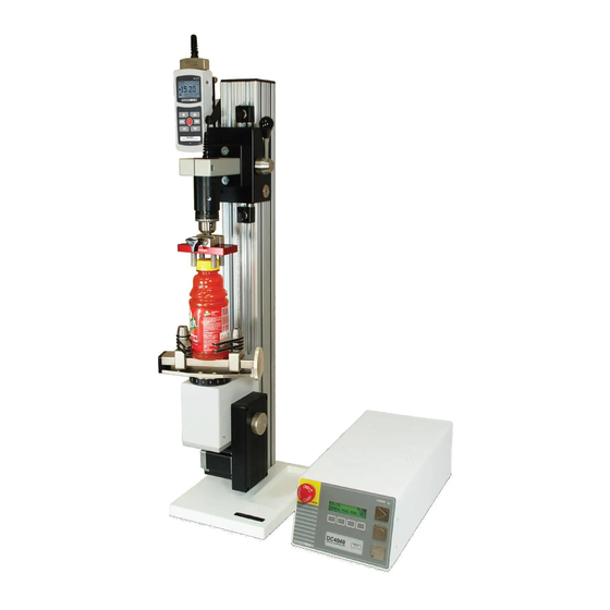
TSTMH-DC-2 With proper usage, we are confident that you will get many years of great service with this product. Mark-10 test stands are ruggedly built for many years of service in laboratory and industrial environments. This User’s Guide provides setup, safety, and operation instructions. -
Page 3: List Of Included Items
Series TSTM-DC Test Stands User’s Guide 1 LIST OF INCLUDED ITEMS Qty. Vertical models Indicator mounting kit Indicator mounting screws, #6-32 x 1/2 Series DC4040 control panel Cable, control panel to test frame Encoder cable Base Column cap with hardware Allen wrench set Power cord Horizontal models... - Page 4 Series TSTM-DC Test Stands User’s Guide In general, the control panel can be mounted at any angle, although extra care should be taken during installation and operation. IMPORTANT: Do not fasten any screws more than 0.25 in [6 mm] into the base of the control panel, or damage to internal components can occur.
- Page 5 Series TSTM-DC Test Stands User’s Guide 2.3 Connections and outputs The power plug and control panel cable must be connected to the rear of the control panel, as shown in the illustration below: 7 1. Fuse 2. Control Panel Cable Connector Plug one end of the cable into this connector, and the other end into the connector as shown in the illustration on the right.
- Page 6 When using a grip, ensure that it secures the sample in such a way that it is prevented from slipping out during a test, preventing a potential safety risk to the operator and others in the vicinity. If using a grip or fixture from a supplier other than Mark-10, ensure that it is constructed of suitably rugged materials and components.
-
Page 7: Operation Basics
Series TSTM-DC Test Stands User’s Guide 4. The test stand should be serviced by a trained technician only. After the above safety checks and procedures have been performed, the test stand may be powered on and is ready for operation. ... - Page 8 Series TSTM-DC Test Stands User’s Guide 3.3 Controls SOFT KEYS Functions are determined by the corresponding text on the display. Initiates movement in the clockwise direction. Initiates movement counterclockwise direction. STOP Stops movement. EMERGENCY Stops movement and disables the test stand until reset. STOP 3.4 Modes overview The TSTM-DC has two functional modes:...
-
Page 9: Test Function Setup
Series TSTM-DC Test Stands User’s Guide 4 TEST FUNCTION SETUP This section provides configuration instructions for each function. After pressing menu, the initial Test Function Setup screen appears as follows: S P E E D : 2 0 . 0 0 E S C <... - Page 10 Series TSTM-DC Test Stands User’s Guide Default setting: off Available settings: off, on A U T O R E T U R N o f f E S C − E N T R Label Description + or – Cycles through the available settings ENTR Returns to the Test Function Setup menu...
- Page 11 Series TSTM-DC Test Stands User’s Guide 4.4 Dwell times (DWELL CW and DWELL CCW) This setting corresponds to the amount of time, in seconds, for which the torque plate stops at the limit during a cycle sequence. Individually set dwell times can be applied to the CW and CCW limits. Note: The dwell time setting is unavailable for an auto return sequence.
- Page 12 The TSTM-DC protects a torque sensor from overload by measuring incoming analog voltage and stopping test stand travel when the programmed percentage of full scale has been reached. The default setting is for Mark-10 instruments (±1V full scale), however, the setting may be changed to ±2V or ±4V to accommodate other instruments.
- Page 13 Series TSTM-DC Test Stands User’s Guide on the front panel, these settings will be ignored, except for Auto Return or Cycling. If either of these functions is turned on, PC control will be turned off. Default setting: CONSOLE Available settings: CONSOLE, PC C O N T R O L : C O N S O L E E S C...
- Page 14 Series TSTM-DC Test Stands User’s Guide Label Description + or – Increases or decreases the value ENTR Returns to the Test Function Setup menu Exits the function without saving changes 4.10 Units of speed (UNITS) This setting corresponds to units of speed and travel measurement. Default setting: RPM Available settings: RPM, °/sec U N I T S :...
- Page 15 Mode, press and hold STOP, then press menu simultaneously, and release both buttons. Scroll to the right until “DISABLE PASSWORD” is displayed. Press ENTR to generate a request code, then provide it to Mark-10, who will supply a corresponding activation code. The process for entering the activation code is as follows: 1.
-
Page 16: Operating Modes
Series TSTM-DC Test Stands User’s Guide 2. Press –> to advance to subsequent digits, and change them in the same manner. 3. Press ENTR when complete. If an incorrect code is entered, the display will revert to the password reset menu. If this happens the above process must be repeated. ... - Page 17 Series TSTM-DC Test Stands User’s Guide 2. Cycling Mode: 1 . 2 7 0 0 0 2 4 me n u m i n ma x S E T 3. PC Control Mode Appears the same as in Basic and Auto Return modes. Label Description menu...
- Page 18 5.3.2 Overload protection The available interface cable is required for overload protection of a Mark-10 torque sensor. If overload protection is enabled, the test stand will stop when the programmed percentage of full scale of the instrument has been reached.
-
Page 19: Communication
Torque sensor / indicator to test stand: Part no. 09-1162 Test stand to PC (RS232): Part no. 09-1056 Test stand to PC (USB): Part no. 09-1056 and RSU100 If not using Mark-10 data collection software, ensure that the software’s communication settings match. ... - Page 20 Series TSTM-DC Test Stands User’s Guide 6.2 PC control mode Motion control and data collection functions may be sent by an external device via user-developed applications. A list of supported ASCII commands is provided below. All commands must be lowercase. Command Description Example...
-
Page 21: Maintenance And Service
2. Attempt to loosen subcomponents of the test stand (ex. fasteners, brackets, etc). All components should be firmly attached. If any looseness is detected, stop using the test stand and contact Mark-10 or a distributor for instructions. 8 TROUBLESHOOTING 1. The control panel displays several error messages, as follows:... -
Page 22: Specifications
Series TSTM-DC Test Stands User’s Guide 1. Ensure all cables are plugged in properly, as described in Setup and Safety section. 2. Ensure that the torque value has not exceeded the overload limits configured in the stand. 3. Ensure that instrument’s set points have been configured properly. Both set points must be enabled, regardless of test direction, with upper limit in the CCW direction, and lower limit in the CW direction. -
Page 23: Dimensions
Series TSTM-DC Test Stands User’s Guide DIMENSIONS in [mm] TSTM-DC ... - Page 24 Series TSTM-DC Test Stands User’s Guide TSTMH-DC CONTROL PANEL ...
- Page 25 Series TSTM-DC Test Stands User’s Guide NOTES ...
- Page 26 Mark-10 Corporation has been an innovator in the force and torque measurement fields since 1979. We strive to achieve 100% customer satisfaction through excellence in product design, manufacturing and customer support. In addition to our standard line of products we ...
Need help?
Do you have a question about the TSTM-DC Series and is the answer not in the manual?
Questions and answers