Advertisement
Advertisement
Table of Contents

Related Manuals for Mark-10 ESM301


Summary of Contents for Mark-10 ESM301
- Page 1 ESM301 / ESM301L Force Test Stand Model User’s Guide...
-
Page 2: Table Of Contents
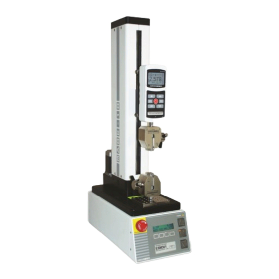
Thank you for purchasing a Mark-10 ESM301 / ESM301L Force Test Stand, designed for producing up to 300 lbF (1.5 kN) of tension or compression force. The ESM301 is an essential component of a force testing system, typically also comprising a force gauge and grips. -
Page 3: Overview
#10-32 coupler, Allen wrench set) Resource CD Note: Unless otherwise indicated, all references to the model ESM301 also apply to the ESM301L. 1.2 Physical Features Note the following physical features of the ESM301. The user’s guide will reference this terminology. -
Page 4: Setup And Safety
The test stand can also be mounted using the ESM301-003 mounting kit. Screws of various lengths are supplied with this kit to accommodate a range of bench thicknesses. Refer to the illustration below for... - Page 5 2.4 Safety / proper usage Typical materials able to be tested by the ESM301 include many manufactured items, such as springs, electronic components, fasteners, caps, films, mechanical assemblies, and many others. Items that...
-
Page 6: Operation Basics
If using a grip or fixture from a supplier other than Mark-10, ensure that it is constructed of suitably rugged materials and components. - Page 7 Model ESM301 / ESM301L Test Stand User’s Guide 4. In those applications where samples can shatter, or other applications that could lead to a hazardous situation, use of a machine guard is strongly recommended. 5. When the test stand is not in use, ensure that the power is turned off to prevent accidental engagement of any of the controls.
-
Page 8: Test Feature Setup
Password protection Standard All ESM301 test stands are shipped in Demo Mode, as explained in the Overview section. After Demo Mode expires, only installed functions will be displayed in Test Feature Setup. The initial Test Feature Setup screen appears as follows: S P E E D : 1 0 . -
Page 9: Setup Menu
Model ESM301 / ESM301L Test Stand User’s Guide Label Description Exits Test Feature Setup, reverts to Operating Mode Scrolls to the previous feature < – – > Scrolls to the next feature ENTR Selects the feature, allowing it to be modified When the features have been configured as desired and are ready to be saved, press ESC to exit Test Feature Setup. - Page 10 Model ESM301 / ESM301L Test Stand User’s Guide 4.1 Speed, Up Speed, Down Speed (SPEED, UP SPEED, DOWN SP) If the independent up and down speed option has not been installed, the up and down speeds will be the same, and is programmed in the SPEED feature. If the independent up and down speed option is installed, UP SPEED and DN SPEED features will be present, and may be set individually.
- Page 11 The programmed distances are relative to the zero position of the crosshead. The travel indicator can be zeroed by pressing and holding STOP for 3 seconds. Default settings: +12.000 in, -12.000 in (ESM301) or +19.000 in., -19.000 in (ESM301L) Available settings: From -19.000 to +19.000 in L I M I T : 2 .
- Page 12 The ESM301 protects a force gauge from overload by measuring incoming analog voltage and stopping crosshead travel when the programmed percentage of full scale has been reached. The default setting is for Mark-10 gauges (±1V), however, the setting may be changed to ±2V or ±4V to accommodate other force gauges.
- Page 13 Model ESM301 / ESM301L Test Stand User’s Guide P R E L O A D : Z E R O , G O E S C − E N T R Label Description + or – Cycles through the available settings listed below:...
- Page 14 Model ESM301 / ESM301L Test Stand User’s Guide Label Description + or – Cycles through the available settings Returns to the Test Feature Setup menu ENTR Exits the feature without saving changes 4.9.1 Break Detection This setting directs the test stand to stop when a sample break has occurred. The test stand stops when the force has decreased to a specified percentage of peak.
- Page 15 Model ESM301 / ESM301L Test Stand User’s Guide Label Description + or – Increases or decreases the value. Returns to the Test Feature Setup menu ENTR Exits the feature without saving changes 4.10 Control Source (CONTROL) This setting corresponds to the source of test stand control. The default value CONSOLE sets the test stand to accept commands only from the console (front panel).
- Page 16 Model ESM301 / ESM301L Test Stand User’s Guide S T O P & P A R : 8 - 1 n E S C − E N T R Label Description + or – Increases or decreases the value. ENTR...
- Page 17 Model ESM301 / ESM301L Test Stand User’s Guide 4.15 Return to Default Settings (DEFAULT SETTINGS) This setting provides a quick return to factory settings, as follows: SPEED: 10 in/min UP SPEED: 10 in/min DOWN SP: 10 in/min AUTO RETURN: CYCLING:...
-
Page 18: Operating Modes
Model ESM301 / ESM301L Test Stand User’s Guide 5 OPERATING MODES 5.1 Mode Overview The ESM301 can be operated in several modes, including combinations of these modes: 1. Basic Mode Manual control of crosshead motion. 2. Auto Return Mode Crosshead moves to a limit switch or force set point, travel distance, preload, or sample break (referred to as soft limits), whichever occurs first. - Page 19 Model ESM301 / ESM301L Test Stand User’s Guide 1. Basic & Auto Return Modes (travel indication option not installed): S P E E D : 0 . 0 0 me n u m i n ma x S E T 2.
- Page 20 5.3.3 Overload Protection The 09-1162 cable is required for overload protection of a Mark-10 force gauge. If overload protection is installed and enabled, the crosshead will stop when the programmed percentage of full scale of the force gauge has been reached.
- Page 21 Model ESM301 / ESM301L Test Stand User’s Guide 5.4 Auto Return Mode In this mode the crosshead moves to whichever limit it encounters first and stops. Then, the crosshead returns at maximum speed to the other limit, whichever occurs first, and stops. The speed at which the crosshead travels is dictated by the SPEED setting or UP SPEED and DN SPEED settings (if the independent up and down speeds option is installed).
- Page 22 Model ESM301 / ESM301L Test Stand User’s Guide 1. Cancel the cycle sequence: Press RESET to stop and reset the cycle sequence. The cycle counter will revert to the number of cycles originally programmed. 2. Resume the cycle sequence: Press UP or DOWN to resume.
-
Page 23: Communication
6 COMMUNICATION 6.1 Setup The ESM301 can transmit force and travel (optional) data to a PC. The following settings are required for proper functioning of all test stand functions and data output: Force gauge / indicator (Series 5 / 7 only):... - Page 24 Model ESM301 / ESM301L Test Stand User’s Guide 6.2 PC Control Mode Motion control and data collection functions may be sent by an external device via user-developed applications. A list of supported ASCII commands is provided below. PC Control is required for all commands, except those highlighted in blue.
-
Page 25: Function Activation
Manual mode Crosshead at upper limit Limit switch status Crosshead at lower limit Commands relating to Mark-10 instruments are not the same as indicated in their respective user’s guides. A list of supported ASCII commands is provided below: Command Description... - Page 26 E S C − E N T R The request code must be supplied to Mark-10 or a distributor, who will then provide a corresponding authorization code to activate the function. The process for entering the authorization code is as follows: 1.
-
Page 27: Troubleshooting
Model ESM301 / ESM301L Test Stand User’s Guide 8 TROUBLESHOOTING 1. The ESM301 displays several error messages, as follows: Error Message Description The force gauge is powered off, in a menu, or not connected to the stand controller. Message appears when overload protection is CHECK GAUGE turned on. -
Page 28: Maintenance And Service
Model ESM301 / ESM301L Test Stand User’s Guide 9 MAINTENANCE AND SERVICE The ESM301 should be operated in a dry and clean area. Under these circumstances only a few periodic maintenance operations are required: 9.1 Acme screw lubrication – twice per year 1. -
Page 29: Specifications
Model ESM301 / ESM301L Test Stand User’s Guide 10 SPECIFICATIONS Load capacity: < 24 in [610 mm]/min: 300 lbF [1.5 kN] > 24 in [610 mm]/min: 200 lbF [1 kN] Standard speed range: 0.5 – 13 in/min [13 – 330 mm/min] Optional speed range: 0.02 –... - Page 30 Model ESM301 / ESM301L Test Stand User’s Guide Mark-10 Corporation has been an innovator in the force and torque measurement fields since 1979. We strive to achieve 100% customer satisfaction through excellence in product design, manufacturing and customer support. In addition to our standard line of products we can provide modifications and custom designs for OEM applications.
Need help?
Do you have a question about the ESM301 and is the answer not in the manual?
Questions and answers