Mark-10 7 Series User Manual
Digital force gauges
Hide thumbs
Also See for 7 Series:
- Quick start manual (3 pages) ,
- Quick start manual (2 pages) ,
- Quick start manual (2 pages)
Table of Contents
Advertisement
Quick Links
Advertisement
Table of Contents

Related Manuals for Mark-10 7 Series


Summary of Contents for Mark-10 7 Series
- Page 1 Series DIGITAL FORCE GAUGES User’s Guide...
-
Page 2: Table Of Contents
User’s Guide Thank you… Thank you for purchasing a Mark-10 Series 7 digital force gauge, designed for tension and compression testing applications from 0.12 lb to 1,000 lb (0.5 N to 5,000 N) full scale. The Series 7 is an essential component of a force testing system, typically also comprising a test stand, grips, and data collection software. -
Page 3: Overview
Series 7 Digital Force Gauges User’s Guide 1 OVERVIEW 1.1 List of included items Part No. Description M7-012 – M7-50 – M7-200 – Qty. M7-20 M7-100 M7-500 12-1049 12-1049 12-1049 Carrying Case 08-1022 08-1022 08-1022 AC adapter body with US, EU, or UK prong 08-1026 08-1026 08-1026... -
Page 4: Power
Series 7 Digital Force Gauges User’s Guide 6. In certain applications, such as the testing of brittle samples that can shatter, or other applications that could lead to a hazardous situation, it is strongly recommended that a machine guarding system be employed to protect the operator and others in the vicinity from shards or debris. 7. -
Page 5: Setup
If using a grip or fixture from a supplier other than Mark-10, ensure that... -
Page 6: Home Screen And Controls
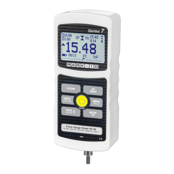
3.2 Installing the USB driver If communicating via USB, install the USB driver provided on the Resource CD. Installation instructions may also be found on the CD or may be downloaded from www.mark-10.com. Caution! Install the USB driver before physically connecting the gauge to a PC with the USB cable. - Page 7 Series 7 Digital Force Gauges User’s Guide Analog indicator to help identify when an overload condition is imminent. The bar increases either to the right or to the left from the midpoint of the graph. Increasing to the right indicates compression load, increasing to the left indicates tension load.
-
Page 8: Digital Filters
Series 7 Digital Force Gauges User’s Guide 4.2 Controls Secondary Primary Function Label Secondary Function Powers the gauge on and off. Press ENTER Various uses, as described in the briefly to power on, press and hold following sections. to power off. Active only when the home screen is displayed. -
Page 9: Set Points
Series 7 Digital Force Gauges User’s Guide DIGITAL FILTERS (1 = Fastest) Current Reading Displayed Reading Two filters are available: Current Reading – Applies to the peak capture rate of the instrument. Displayed Reading – Applies to the primary reading on the display. Available settings: 1,2,4,8,16,32,64,128,256,512,1024,2048,4096,8192. -
Page 10: Break Detection
6.3 Using Set Points to Control Mark-10 Motorized Test Stands When using set points to stop/cycle crosshead motion on certain Mark-10 test stands, the upper set point must always be a value in the tension direction, and the lower set point must always be a value in the compression direction. - Page 11 Series 7 Digital Force Gauges User’s Guide 7.1 Configuration To enable Break Detection and configure the automatic functions, select Break Detection from the main menu. The display appears as follows: BREAK DETECTION Disabled Enabled-End Test Enabled-Abort + Break Settings + Auto Output + More Select “+ More”...
-
Page 12: Operating Modes
Automatically toggle the SP1, SP2, or SP3 pins (active low). If not required, select “NONE”. To stop certain Mark-10 test stands when a break occurs, specify SP2 if the break is in the tension (upwards) direction, or SP1 for the compression Output Pin (downwards) direction. - Page 13 Series 7 Digital Force Gauges User’s Guide External Trigger (ET) Data Capture (CAPT) Peak (2PK) To cycle between the modes, press MODE while in the home screen. Refer to the following sections for details for each mode: 8.1 Real Time (RT) The primary reading corresponds to the live measured reading.
- Page 14 Automatically toggle the SP1, SP2, or SP3 pins (active low). If not required, select “NONE”. To stop a Mark-10 test stand when averaging is completed, specify SP2 Output Pin if moving in the tension (upwards) direction, or SP1 for the compression...
- Page 15 “snapshot” view of applied forces. It is possible to capture the reading with a normally open contact (high to low transition of the trigger signal) or a normally closed contact (low to high transition). Certain Mark-10 test stand may be automatically stopped when an external trigger has occurred.
- Page 16 0.1 uF GAUGE USER - SUPPLIED Note: Custom cabling is required to connect to a switch, or to connect a switch and a Mark-10 test stand simultaneously. 8.6 Data Capture (CAPT) This mode of operation is used to capture and store continuous data in the gauge’s memory. The capture frequency can be adjusted to accommodate quick-action as well as longer duration tests.
- Page 17 Series 7 Digital Force Gauges User’s Guide DATA CAPTURE Enabled Period (H:M:S.x) 00 :00 :00 .00007 + Start Condition + Stop Condition + Auto Settings Function Description Enabled If enabled, CAPT appears as one of the operating modes. Period The capture period may be adjusted by pressing the keys to change the value of the hours (H), minutes (M), seconds (S), and fractions of seconds (x) fields.
- Page 18 The DATA key is manually pressed. When data capture has stopped, the data may be automatically transmitted in bulk to a PC application (not supported by Mark-10 data collection software). Data may also be transmitted manually through the Memory section.
- Page 19 Series 7 Digital Force Gauges User’s Guide 8.7.1 Configuration Several functions can be performed automatically upon detection of the second peak: 1. Transmit the first peak reading and/or… 2. Transmit the second peak reading and/or… 3. Save the first peak value to memory and/or… 4.
- Page 20 Output Pin Automatically toggle the SP1, SP2, or SP3 pins (active low). If not required, select “NONE”. To stop certain Mark-10 test stands when a 1 peak capture sequence is completed, specify SP2 if moving in the tension (upwards) direction, or SP1 for the compression (downwards) direction.
-
Page 21: Data Memory And Statistics
Series 7 Digital Force Gauges User’s Guide 9 DATA MEMORY AND STATISTICS Series 7 gauges have storage capacity of 5,000 data points. Readings may be stored, viewed, and output to an external device. Individual or all data points may be deleted. Statistics are calculated for the data in memory. -
Page 22: Footswitch
Series 7 Digital Force Gauges User’s Guide 9.5 Output Data & Stats Press ENTER to output data and statistics to an external device. The display will show, “SENDING DATA”, then “SENDING STATS…”, then “DATA SENT”, then “STATS SENT”. If there was a problem with communication, the display will show, “DATA NOT SENT”... -
Page 23: Coefficient Of Friction
Series 7 Digital Force Gauges User’s Guide FOOTSWITCH 2 Step 3: NONE * Active Low (NO) Active High (NC) Function Description Enabled Press ENTER to enable, and an asterisk appears. Step 1 / 2 / 3 Set the desired command. Available commands: ?, ?C, ?PT, ?PC, ?A, Z, CLR, PM, DATA Key, and NONE. -
Page 24: Custom Unit
Series 7 Digital Force Gauges User’s Guide 12 CUSTOM UNIT A user-defined unit of measurement may be configured for special applications. A base unit is specified, along with a multiplier, and 5-character name. Typical applications: 1. To measure the torque produced by pressing on a lever in a mechanical assembly, configure the multiplier based on the length of the lever, thereby converting a unit such as N into Ncm. - Page 25 Select the baud rate as required for the application. It must be set to the same value as the receiving device. When communicating with a Mark-10 test stand controller, the baud rate must be set to 115,200. 13.1.2 Data Format Select the desired data format.
- Page 26 Series 7 Digital Force Gauges User’s Guide After the settings have been saved, revert to the home screen. An icon appears in the lower left corner of the display, as follows: This indicates that automatic data output has been armed. Automatic output of data may be initiated by pressing DATA or by sending the appropriate ASCII command from an external device (see Command Set sub-section for details).
- Page 27 Series 7 Digital Force Gauges User’s Guide 13.5 I/O Connector Pin Diagram (DB-9HD-15 female) Input / Pin No. Description Output Signal Ground Tension Overload * Output * RS-232 Receive Input RS-232 Transmit Output +12V DC Input / Output Analog Output Output Compression Overload * Output *...
- Page 28 Series 7 Digital Force Gauges User’s Guide 13.6 Command Set / Gauge Control Language 2 (GCL2) Series 7 force gauges may be controlled by an external device through the RS-232 or USB channels. The following is a list of supported commands and their explanations. All commands must be terminated by a CR (Carriage Return) character, 0x0D, or a CR-LF (Carriage Return –...
- Page 29 Series 7 Digital Force Gauges User’s Guide USB/RS-232 Communication FULL USB/RS-232 transmission with units USB/RS-232 transmission without units (only numeric values) AOUTn Auto-transmit n times per second n=1, 2, 5, 10, 25, 50, 125, 250. 0=disabled Note: n = 1 = yields 50 times per second. This is provided for backward compatibility with legacy gauges.
-
Page 30: Calibration
Series 7 Digital Force Gauges User’s Guide Example return strings: -0.486 lbF<CR><LF> 0.486 lbF of tension force 1.724 N<CR><LF> 1.724 N of compression force The number of digits after the decimal point is dependent of the instrument’s capacity and resolution. By default, the minus sign (-) indicates tension, and the absence of a sign indicates compression. - Page 31 Series 7 Digital Force Gauges User’s Guide CALIBRATION Enter # cal points (1 to 10) Compression: Tension: The gauge can be calibrated at up to 10 points in each direction. Enter the number of calibration points for each direction (compression and tension). At least one point must be selected for each direction.
- Page 32 Series 7 Digital Force Gauges User’s Guide CALIBRATION CALIBRATION OFFSET OFFSET Sensor passed Sensor failed Analog passed Analog failed If failed: 6. The following screen appears after the offsets have been calculated: CALIBRATION COMPRESSION Attach necessary weight fixtures, then press ENTER. Attach weight fixtures (brackets, hooks, etc), as required.
- Page 33 Series 7 Digital Force Gauges User’s Guide 10. The display appears as follows: CALIBRATION COMPRESSION Apply load 1 OF 5 Enter load: 2.000 lbF Press ENTER. Use the UP and DOWN keys to adjust the load value as required. The load values default to even increments, as indicated by the previously entered number of data points (even increments are recommended for best results).
-
Page 34: Passwords
Series 7 Digital Force Gauges User’s Guide 14. Any errors are reported by the following screens: CALIBRATION Units must be gF. Please try again Press ENTER. Displayed at the start of calibration if a disallowed unit is selected. CALIBRATION Load not stable. Please try again. - Page 35 Series 7 Digital Force Gauges User’s Guide Select “+ More” for additional options: PASSWORDS 2 DATA Key CLEAR Key POWER Key 15.1 Calibration Password Select Calibration from the sub-menu. The display appears as follows: CALIBRATION PASSWORD Disabled Enabled Set Password (0000 –...
-
Page 36: Other Settings
If the password has been misplaced, it can be reset. Press ENTER to generate a request code. The request code must be supplied to Mark-10 or a distributor, who will then provide a corresponding authorization code. Enter the activation code to disable the password. - Page 37 Series 7 Digital Force Gauges User’s Guide Selection Description Backlight to be off upon powering on the gauge. Backlight to be on upon powering on the gauge. Auto Backlight to be on upon powering gauge, but will shut off after a period of inactivity (as defined in the Automatic Shutoff sub-section).
-
Page 38: Specifications
The following screen is displayed at power-up and can be accessed at any time by selecting Information from the menu: Digital Force Gauge Series 7 Model No: M7-50 Serial No: 1234567 Version: 1.0 (c) Mark-10 Corp. 17 SPECIFICATIONS 17.1 General Accuracy: ±0.1% of full scale Sampling rate: 14,000 Hz Power: AC or rechargeable battery. - Page 39 Series 7 Digital Force Gauges User’s Guide 17.2 Factory Default Settings Parameter Setting Set points Upper Disabled (defaults to 80% of full scale, compression, when enabled) Lower Disabled (defaults to 40% of full scale, compression, when enabled) Filters Current Displayed 2048 Average mode Disabled...
- Page 40 Series 7 Digital Force Gauges User’s Guide Keys Enabled Alerts Enabled Set Points Momentary Automatic Shutoff Enabled Set Minutes Backlight Auto Set Minutes Initial Settings Units Mode Real Time Passwords All disabled 17.3 Capacity x Resolution Model M7-012 0.12 x 0.00002 2 x 0.0005 50 x 0.01 0.5 x 0.0001...
- Page 41 Series 7 Digital Force Gauges User’s Guide 17.5 Dimensions IN [MM] Thread Flat M7-012 – M7-100 #10-32M UNF 5/16 [7.94] M7-200 – M7-500 5/16-18M UNC 5/16 [7.94]...
- Page 42 Series 7 Digital Force Gauges User’s Guide Mark-10 Corporation has been an innovator in the force and torque measurement fields since 1979. We strive to achieve 100% customer satisfaction through excellence in product design, manufacturing and customer support. In addition to our standard line of products we can provide modifications and custom designs for OEM applications.
Need help?
Do you have a question about the 7 Series and is the answer not in the manual?
Questions and answers