Table of Contents
Advertisement
Advertisement
Table of Contents

Related Manuals for Mark-10 MTT03C-12


Summary of Contents for Mark-10 MTT03C-12
- Page 1 TT03 Series DIGITAL TORQUE GAUGES User’s Guide...
-
Page 2: Table Of Contents
Series TT03 Digital Torque Gauges User’s Guide Thank you… Thank you for purchasing a Mark-10 Series TT03 digital torque gauge, designed for handheld or test stand use. With proper usage, we are confident that you will get many years of great service with this product. -
Page 3: Overview
User’s Guide ® ® Download at: www.mark-10.com/resources 1.2 Safety / Proper Usage Caution! Note the torque gauge’s capacity before use and ensure that the capacity is not exceeded. Producing a torque greater than 150% of the gauge’s capacity can damage the internal sensor. An overload can occur whether the gauge is powered on or off. -
Page 4: Power
Series TT03 Digital Torque Gauges User’s Guide 2 POWER The TT03 is powered either by an 8.4V NiMH rechargeable battery or by an AC adapter. Since these batteries are subject to self discharge, it may be necessary to recharge the unit after a prolonged period of storage. -
Page 5: Setup
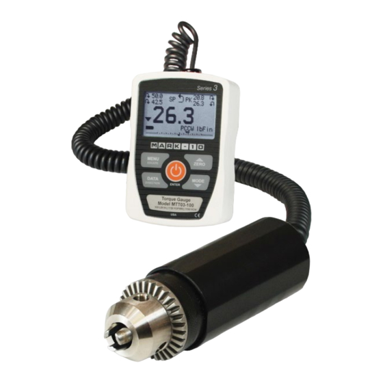
The torque sensor portion of the gauge (shown in Figure 3.1) can be mounted directly to a Mark-10 torque test stand or tabletop mounting kit without the need for any additional adapters. Flat surfaces are provided to prevent rotation within a fixture. -
Page 6: Home Screen And Controls
Series TT03 Digital Torque Gauges User’s Guide 4 HOME SCREEN AND CONTROLS 4.1 Home Screen Name Description Measurement – indicates clockwise direction direction – indicates counter-clockwise direction indicator These indicators are used throughout the display and menu. Peaks The maximum measured clockwise and counter-clockwise readings. These readings are reset by pressing ZERO or by powering the gauge off and on. - Page 7 Series TT03 Digital Torque Gauges User’s Guide Battery / AC Either the AC adapter icon or battery power icon will be shown, depending on adapter indicator power conditions. Refer to the Power section for details. High / low limit Correspond to the programmed set points. Indicator definitions are as follows: indicators –...
-
Page 8: Operating Modes
Series TT03 Digital Torque Gauges User’s Guide 5 OPERATING MODES Caution! In any operating mode, if the capacity of the instrument has been exceeded by more than 110%, the display will show “OVER” to indicate an overload. A continuous audible tone will be sounded (if beeps are enabled) until the MENU key has been pressed or the load has been reduced to a safe level. -
Page 9: Digital Filters
Series TT03 Digital Torque Gauges User’s Guide 7 DIGITAL FILTERS Digital filters are provided to help smooth out the readings in situations where there is mechanical interference in the work area or test sample. These filters utilize the moving average technique in which consecutive readings are pushed through a buffer and the displayed reading is the average of the buffer contents. -
Page 10: Set Point Indicators
Series TT03 Digital Torque Gauges User’s Guide 8 SET POINT INDICATORS 8.1 General Information Set points are useful for tolerance checking (pass/fail). Two limits, high and low, are specified and stored in the non-volatile memory of the instrument and the primary reading is compared to these limits. 8.2 Configuration To configure set points, select Set Points from the menu. -
Page 11: Communications And Outputs
Series TT03 Digital Torque Gauges User’s Guide 9 COMMUNICATIONS AND OUTPUTS 9.1 Communication Settings To set up communication settings, select USB Settings from the menu. The screen appears as follows: USB SETTINGS + Baud Rate + Data Format Communication settings are permanently set to the following: Data Bits: Stop Bits: Parity:... - Page 12 Series TT03 Digital Torque Gauges User’s Guide 9.2 Data Output Communication with Series TT03 torque gauges is achieved through the micro USB port located along the left side of the housing, as shown in the illustration in the Power section. Communication is possible only when the gauge is in the main operating screen (i.e.
-
Page 13: Calibration
Series TT03 Digital Torque Gauges User’s Guide 10 CALIBRATION 10.1 Initial Physical Setup The sensor should be mounted vertically to a test stand or fixture rugged enough to withstand a load equal to the full capacity of the instrument. Vertical orientation is preferable to avoid side loading, which can affect the readings. - Page 14 Series TT03 Digital Torque Gauges User’s Guide 10.2 Calibration Procedure 1. Select Calibration from the menu. The display appears as follows: CALIBRATION Enter # cal points (1 to 10) Clockwise: Counter-clockwise: The sensor can be calibrated at up to 10 points in each direction. Enter the number of calibration points for each direction.
- Page 15 Series TT03 Digital Torque Gauges User’s Guide CALIBRATION CALIBRATION OFFSET OFFSET Sensor passed Sensor failed Analog passed Analog failed If failed: 5. The following screen appears after the offsets have been calculated: CALIBRATION CLOCKWISE Attach necessary weight fixtures, then press ENTER. Keep the sensor in a vertical position, as explained in the previous sub-section.
- Page 16 Series TT03 Digital Torque Gauges User’s Guide Remove the torque applied in Step 7, leave the fixtures in place, then press ZERO. 9. The display appears as follows: CALIBRATION CLOCKWISE Apply load 1 OF 5 Enter load: 10.00 lbFin Press ENTER. Use the UP and DOWN keys to adjust the torque value as required.
-
Page 17: Other Settings
Series TT03 Digital Torque Gauges User’s Guide CALIBRATION Load not stable. Please try again. Ensure that the load is not swinging, oscillating, or vibrating in any manner. Then try again. CALIBRATION CLOCKWISE Load too low. Please try again. The calibration load does not match the set value. CALIBRATION COUNTER-CLOCKWISE Load too close... - Page 18 Series TT03 Digital Torque Gauges User’s Guide 11.2 Backlight Several initial settings are available, upon powering on the gauge. To access these settings, select Backlight from the menu. The display appears as follows: BACKLIGHT Auto Set Minutes Selection Description Backlight to be off upon powering on the gauge. Backlight to be on upon powering on the gauge.
- Page 19 11.7 Information / Welcome Screen The following screen is displayed at power up and can be accessed at any time by selecting Information from the menu: Digital Torque Gauge Series TT03 Model No: MTT03-50 Serial No: 1234567 Version: 1.0 (c) Mark-10 Corp.
-
Page 20: Specifications
1.8 lb [0.8 kg] Carrying case, AC adapter, battery, USB cable, NIST-traceable certificate of Included accessories: calibration Environmental 40 - 100°F, max. 96% humidity, non-condensating requirements: Warranty: 3 years (see individual statement for further details) Literature & Software: Download at: www.mark-10.com/resources... - Page 21 Series TT03 Digital Torque Gauges User’s Guide 12.2 Factory Settings Parameter Setting Set points Upper Disabled (defaults to 80% of full scale, clockwise, when enabled) Lower Disabled (defaults to 40% of full scale, clockwise, when enabled) Filters Current Displayed Backlight Auto Minutes USB Output...
- Page 22 Series TT03 Digital Torque Gauges User’s Guide Mark-10 Corporation has been an innovator in the force and torque measurement fields since 1979. We strive to achieve 100% customer satisfaction through excellence in product design, manufacturing and customer support. In addition to our standard line of products we can provide modifications and custom designs for OEM applications.
Need help?
Do you have a question about the MTT03C-12 and is the answer not in the manual?
Questions and answers