Table of Contents
Advertisement
Advertisement
Table of Contents

Related Manuals for Mark-10 TT01 Series


Summary of Contents for Mark-10 TT01 Series
- Page 1 TT01 Series DIGITAL CAP TORQUE TESTERS User’s Guide...
-
Page 2: Table Of Contents
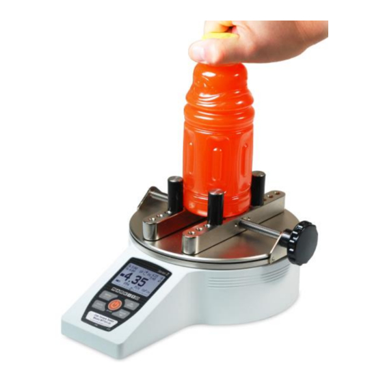
User’s Guide Series TT01 Digital Cap Torque Testers Thank you… Thank you for purchasing a Mark-10 Series TT01 digital cap torque tester, designed to measure bottle cap application and removal torque. With proper usage, we are confident that you will get many years of great service with this product. -
Page 3: Overview
09-1165 USB cable gauge evaluation software, User’s Guide ® ® USB driver, MESUR Lite software, MESUR Download at: www.mark-10.com/resources Optional Items CT001 Flat jaws set, 2 CT002 Carrying case CT003 Adjustable jaws set, 2 Set of 2.5” sample gripping posts, 4 CT005 Set of 4”... -
Page 4: Power
User’s Guide Series TT01 Digital Cap Torque Testers 6. In certain applications, such as the testing of brittle samples that can shatter, or other applications that could lead to a hazardous situation, it is strongly recommended that a machine guarding system be employed to protect the operator and others in the vicinity from shards or debris. -
Page 5: Setup
The tester can be mounted to a bench using the four threaded holes on the underside of the base. 3.2 Installing the USB driver If communicating via USB, install the USB driver available at: www.mark-10.com/downloads Caution! Install the USB driver before physically connecting the tester to a PC with the USB cable. -
Page 6: Home Screen And Controls
User’s Guide Series TT01 Digital Cap Torque Testers 4 HOME SCREEN AND CONTROLS 4.1 Home Screen Name Description – indicates clockwise direction Measurement – indicates counter-clockwise direction direction indicator These indicators are used throughout the display and menu. The maximum measured clockwise and counter-clockwise readings. These Peaks readings are reset by pressing ZERO or by powering the tester off and on. - Page 7 User’s Guide Series TT01 Digital Cap Torque Testers Battery / AC Either the AC adapter icon or battery power icon will be shown, depending on adapter indicator power conditions. Refer to the Power section for details. Correspond to the programmed set points. Indicator definitions are as follows: –...
-
Page 8: Operating Modes
User’s Guide Series TT01 Digital Cap Torque Testers 5 OPERATING MODES Caution! In any operating mode, if the capacity of the instrument has been exceeded by more than 110%, the display will show “OVER” to indicate an overload. A continuous audible tone will be sounded (if tones are enabled) until the MENU key has been pressed or the load has been reduced to a safe level. -
Page 9: Set Points
User’s Guide Series TT01 Digital Cap Torque Testers DIGITAL FILTERS (1 = Fastest) Current Reading Displayed Reading Two filters are available: Current Reading – Applies to the peak capture rate of the instrument. Displayed Reading – Applies to the primary reading on the display. Available settings: 1,2,4,8,16,32,64,128,256,512,1024. -
Page 10: Break Detection
User’s Guide Series TT01 Digital Cap Torque Testers – the displayed value is greater than the upper force limit (NO GO HIGH) – the displayed value is between the limits (GO) – the displayed value is less than the lower force limit (NO GO LOW) Note: Set point indicators reference the displayed reading, not necessarily the current live load. - Page 11 User’s Guide Series TT01 Digital Cap Torque Testers BREAK DETECTION Enabled + Break Settings + Auto Output Auto Storage Auto Zero Any combination of the above functions may be selected. Function Description Arms the break detection function. When enabled, the letter “B” will appear on the home screen, between the Mode and Unit indicators.
-
Page 12: First / Second Peak
User’s Guide Series TT01 Digital Cap Torque Testers AUTO OUTPUT SETTINGS RS232/USB Output Mitutoyo Output Output Pin: NONE Parameter Description RS232/USB Output Automatically output the peak when the break (% Drop) is detected. Mitutoyo Output Automatically output the peak when the break (% Drop) is detected. Automatically toggle the SP1, SP2, or SP3 pins (active low). - Page 13 User’s Guide Series TT01 Digital Cap Torque Testers Function Description Enabled If enabled, 2PK appears as one of the operating modes. In the main display, the Peak readings will reference the first and second peaks – first peak on top, second peak below.
-
Page 14: Data Memory And Statistics
User’s Guide Series TT01 Digital Cap Torque Testers 10.3 Auto Output Settings Select the output type. Select RS-232/USB and/or Mitutoyo outputs, and select First and/or Second peaks. The display appears as follows: AUTO OUTPUT SETTINGS RS232/USB Output Mitutoyo Output First Peak Second Peak 11 DATA MEMORY AND STATISTICS Series TT01 testers have storage capacity of 1,000 data points. - Page 15 Press ENTER to output data to an external device. The display will show, “SENDING DATA…”, then “DATA SENT”. If there was a problem with communication, the display will show, “DATA NOT SENT”. Saved data can be downloaded by some Mark-10 data collection programs. Refer to their respective user’s guides for details.
-
Page 16: Communications And Outputs
User’s Guide Series TT01 Digital Cap Torque Testers *** WARNING *** DATA IN MEMORY WILL BE LOST CANCEL POWER OFF If no option is selected, this screen will be displayed indefinitely, or until battery power has been depleted. 12 COMMUNICATIONS AND OUTPUTS Communication with the TT01 tester is achieved through the micro USB or 15-pin serial ports located in the rear of the housing, as shown in the illustration in the Power section. - Page 17 User’s Guide Series TT01 Digital Cap Torque Testers Selection Description Numeric + Units Output format includes the value and unit of measure. Clockwise values have positive polarity, counter-clockwise values have negative polarity. Numeric Only Output format includes the value only. Polarity same as above. Invert Polarity Clockwise values have negative polarity, counter-clockwise values have positive polarity.
- Page 18 User’s Guide Series TT01 Digital Cap Torque Testers polarity of the signal is positive for clockwise and negative for counter-clockwise. 12.4 DATA Key Settings To configure the functions of the DATA key, select DATA Key from the menu. The display appears as follows: DATA KEY RS232/USB Output...
- Page 19 User’s Guide Series TT01 Digital Cap Torque Testers 12.5 I/O Connector Pin Diagram (female) Pin No. Description Input / Output Signal Ground Counter-clockwise Overload Output RS-232 Receive Input RS-232 Transmit Output +12V DC Input/Output Analog Output Output Clockwise Overload Output Mitutoyo Clock Output Output Bit 2...
-
Page 20: Calibration
Suitable calibration equipment is required, and caution should be taken while handling such equipment. The AC1036 calibration kit is available from Mark-10, shown at left. Note the circular groove in the top plate, shown right, which accommodates a cable for suspension of deadweights. - Page 21 User’s Guide Series TT01 Digital Cap Torque Testers 3. To escape the Calibration menu at any time, press ESCAPE. The display appears as follows: CALIBRATION NOT COMPLETE Cancel Exit w/o saving Selecting “Cancel” will revert back to the Calibration setup. Selecting “Exit w/o saving” will return to the menu without saving changes.
- Page 22 User’s Guide Series TT01 Digital Cap Torque Testers 7. The display appears as follows: CALIBRATION CLOCKWISE Optionally exercise sensor, then press ENTER. Optionally exercise the torque sensor several times (at full scale, if possible), then press ENTER. 8. The display appears as follows: CALIBRATION CLOCKWISE Gain adjust...
- Page 23 User’s Guide Series TT01 Digital Cap Torque Testers CALIBRATION CLOCKWISE COMPLETE Reverse direction for counter-clockwise. Attach necessary weight fixtures, then press ENTER. Press ENTER. 12. Attach weight fixtures. The following screens will step through the same procedure as with the compression direction.
-
Page 24: Passwords
User’s Guide Series TT01 Digital Cap Torque Testers CALIBRATION COUNTER-CLOCKWISE Load too close to previous. Please try again. The entered calibration point is too close to the previous point. 14 PASSWORDS Two separate passwords may be set to control access to the Calibration section and to the menu and other keys. -
Page 25: Other Settings
If the password has been misplaced, it can be reset. Press ENTER to generate a request code. The request code must be supplied to Mark-10 or a distributor, who will then provide a corresponding activation code. Enter the activation code to disable the password. - Page 26 User’s Guide Series TT01 Digital Cap Torque Testers BACKLIGHT Auto Set Minutes Selection Description Backlight to be off upon powering on the tester. Backlight to be on upon powering on the tester. Auto Backlight to be on upon powering tester, but will shut off after a period of inactivity (as defined in the Automatic Shutoff sub-section).
- Page 27 RESTORE DEFAULT SETTINGS? 15.7 Information / Welcome Screen The following screen is displayed at power-up and can be accessed at any time by selecting Information: Digital Torque Tester Series TT01 Model No: MTT01-50 Serial No: 1234567 Version: 1.0 (c) Mark-10 Corp.
-
Page 28: Specifications
Set of four posts, AC adapter, battery, USB cable, NIST-traceable certificate of calibration Environmental requirements: 40 - 100°F, max. 93% humidity, non-condensating Warranty: 3 years (see individual statement for further details) Literature & Software: Download at: www.mark-10.com/resources 16.2 Dimensions IN [MM]... - Page 29 User’s Guide Series TT01 Digital Cap Torque Testers 16.3 Factory Settings Parameter Setting Set points Upper Disabled (defaults to 80% of full scale, clockwise, when enabled) Lower Disabled (defaults to 40% of full scale, clockwise, when enabled) Filters Current Displayed DATA Key Functions RS-232/USB Output Enabled...
- Page 30 User’s Guide Series TT01 Digital Cap Torque Testers Mark-10 Corporation has been an innovator in the force and torque measurement fields since 1979. We strive to achieve 100% customer satisfaction through excellence in product design, manufacturing and customer support. In addition to our standard line of products we can provide modifications and custom designs for OEM applications.
Need help?
Do you have a question about the TT01 Series and is the answer not in the manual?
Questions and answers