Table of Contents
Advertisement
Quick Links
Advertisement
Table of Contents

Related Manuals for Mark-10 WT3-200


Summary of Contents for Mark-10 WT3-200
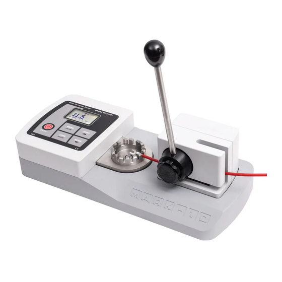
- Page 1 WT3-200 Model WIRE TERMINAL PULL TESTER User’s Guide...
-
Page 2: Table Of Contents
Our technical support and engineering teams are eager to assist you. Before use, each person who is to use the WT3-200 should be fully trained in appropriate operation and safety procedures. TABLE OF CONTENTS OVERVIEW ............2... -
Page 3: Overview
Model WT3-200 Wire Terminal Pull Tester User’s Guide 1 OVERVIEW 1.1 List of included items Qty. Part No. Description 08-1026 Battery (inside the tester) Certificate of calibration 09-1165 USB cable Resource CD (USB driver, user’s guides, MESUR Lite software, MESUR gauge DEMO software, User’s Guide) -
Page 4: Power
Model WT3-200 Wire Terminal Pull Tester User’s Guide 2 POWER The tester is powered either by an 8.4V NiMH rechargeable battery or by an AC adapter. Since these batteries are subject to self discharge, it may be necessary to recharge the unit after a prolonged period of storage. -
Page 5: Mechanical Setup
Model WT3-200 Wire Terminal Pull Tester User’s Guide 3 SETUP 3.1 Assembly The lever is shipped disassembled from the unit to prevent damage in transit. To install, match the pin on the cam mechanism with the corresponding blind hole in the lever hub. Then, tighten the plastic knob into the threaded hole in the lever hub. - Page 6 Model WT3-200 Wire Terminal Pull Tester User’s Guide Fig. 3.4 Rotating the lever 5. When the test is complete, rotate the lever clockwise until the end of travel. The cams will open and the wire will be released. 3.4 Installing the ring terminal fixture To install or uninstall the standard terminal fixture or optional ring terminal fixture, loosen the screw in the center of the fixture, remove, place the other fixture in the receptacle, and re-tighten the screw.
-
Page 7: Home Screen And Controls
Model WT3-200 Wire Terminal Pull Tester User’s Guide 4 HOME SCREEN AND CONTROLS 4.1 Home Screen Name Description Tension / - Tension (pull) direction. compression indicator - Compression (push) direction. Not typically used. These indicators are used throughout the display and menu. - Page 8 Model WT3-200 Wire Terminal Pull Tester User’s Guide Battery / AC Either the AC adapter icon or battery power icon will be shown, depending on adapter indicator power conditions. Refer to the Power section for details. High / low limit Correspond to the programmed set points.
-
Page 9: Operating Modes
“OVER” to indicate an overload. A continuous audible tone will be sounded until the MENU key has been pressed or the load has been reduced to a safe level. Three operating modes are possible with the WT3-200. To cycle between the modes, press MODE while in the home screen. -
Page 10: Set Points
Model WT3-200 Wire Terminal Pull Tester User’s Guide DIGITAL FILTERS (1 = Fastest) Current Reading Displayed Reading Two filters are available: Current Reading – Applies to the peak capture rate of the instrument. Displayed Reading – Applies to the primary reading on the display. -
Page 11: Data Memory And Statistics
8.2 Set Point Outputs Schematic 9 DATA MEMORY AND STATISTICS The WT3-200 has storage capacity of 1,000 data points. Readings may be stored, viewed, and output to an external device. Individual, or all, data points may be deleted. Statistics are calculated for the data presently in memory. - Page 12 Press ENTER to output data to an external device. The display will show, “SENDING DATA…”, then “DATA SENT”. If there was a problem with communication, the display will show, “DATA NOT SENT”. Saved data can be downloaded by Mark-10 data collection programs. Refer to their respective user’s guides for details.
-
Page 13: Communications
User’s Guide 10 COMMUNICATIONS Communication with the WT3-200 is achieved through the micro USB or 15-pin serial ports located at the bottom of the instrument, as shown in the illustration in the Power section. Communication is possible only when the tester is in the main operating screen (i.e. not in a menu or configuration area). - Page 14 5. After Windows as restarted, plug in the device. The following will occur: Windows 7 Operating Systems – When the Mark-10 USB device has been plugged into a USB port, the driver will automatically be found. When the driver installation is complete, a message will appear as follows: “The MARK-10 USB DEVICE driver is now installed and ready to use”.
- Page 15 8. The next, and final, screen appears as follows: Click “Finish”. The Mark-10 USB device is now installed and ready to use. The COM port number assigned by Windows may be identified in Device Manager, or in the communication application being used, such as MESURgauge or HyperTerminal.
- Page 16 Both directions are formatted with positive polarity. May be selected in addition to the Numeric + Units / Numeric Only selection. 10.2.3 Data Communication Individual data points may be transmitted by pressing DATA. The WT3-200 will also respond to the following ASCII commands: Request the displayed reading...
- Page 17 Model WT3-200 Wire Terminal Pull Tester User’s Guide MITUTOYO BCD Disabled Ena w/o Polarity Ena w/Polarity 10.4 Break Detection Three functions can be triggered automatically upon sample break (break detection), defined as a 50% drop in load from the peak: 1.
- Page 18 Model WT3-200 Wire Terminal Pull Tester User’s Guide Trig. Threshold Sets the percentage of full scale at which the break detection feature becomes active. This threshold is provided to ignore peaks that can occur during sample loading and unloading. Available settings: 5-50%, in 5% increments.
-
Page 19: Calibration
Model WT3-200 Wire Terminal Pull Tester User’s Guide 10.7 I/O Connector Pin Diagram (DB-9HD-15 female) Pin No. Description Input / Output Signal Ground Tension Overload Output RS-232 Receive Input RS-232 Transmit Output +12V DC Output Analog Output Output Compression Overload... - Page 20 Model WT3-200 Wire Terminal Pull Tester User’s Guide The tester can be calibrated at up to 10 points. Enter the number of calibration points (at least one point must be selected). Note: To achieve the accuracy specification of ±0.2%, it is recommended to calibrate the tester at 5 or more evenly spaced increments, such as 40, 80, 120, 160, and 200 lb loads.
- Page 21 Model WT3-200 Wire Terminal Pull Tester User’s Guide CALIBRATION Attach necessary weight fixtures. THEN PRESS ENTER Attach weight fixtures (brackets, hooks, etc), as required. Do not yet attach any weights or apply any calibration loads. Then press ENTER. 7. The display will appear as follows:...
- Page 22 Model WT3-200 Wire Terminal Pull Tester User’s Guide Use the UP and DOWN keys to adjust the load value as required. The load values default to evenly spaced increments, as indicated by the previously entered number of data points. Apply the calibration load.
-
Page 23: Passwords
Model WT3-200 Wire Terminal Pull Tester User’s Guide CALIBRATION LOAD TOO CLOSE TO PREVIOUS PLEASE TRY AGAIN The entered calibration point is too close to the previous point. 12 PASSWORDS Two separate passwords may be set to control access to the Calibration section and to the menu and other keys. -
Page 24: Other Settings
If the password has been misplaced, it can be reset. Press ENTER to generate a request code. The request code must be supplied to Mark-10 or a distributor, who will then provide a corresponding authorization code. Enter the activation code to disable the password. - Page 25 Model WT3-200 Wire Terminal Pull Tester User’s Guide 13.2 Backlight Several initial settings are available upon powering on the tester. To access these settings, select Backlight from the menu. The display will appear as follows: BACKLIGHT Auto Set Minutes Select Off for the backlight to be off upon powering on the tester.
- Page 26 Model WT3-200 Wire Terminal Pull Tester User’s Guide 13.5 Initial settings This section is used to configure the initial settings upon powering on the tester. The initial units of measurement and the primary reading measurement mode may be configured. To access these settings, select Initial Settings from the menu.
-
Page 27: Specifications
Model WT3-200 Wire Terminal Pull Tester User’s Guide 14 SPECIFICATIONS 14.1 General Force Capacity: 200 x 0.1 lbF | 3200 x 2 ozF | 100 x 0.05 kgF | 1000 x 0.5 N | 1 x 0.0005 kN Accuracy: ±0.2% of full scale Wire diameter range: AWG30 - AWG 3 [0.03 - 0.25 in (0.8 - 6.3 mm)]... - Page 28 Model WT3-200 Wire Terminal Pull Tester User’s Guide RS-232/USB Output Disabled Mitutoyo Output Disabled Automatic Storage Disabled Automatic Zero Disabled Break Detection Settings Trigger Threshold Auto Zero Delay 3 sec. Automatic Shutoff Enabled Minutes Beeps Keys Enabled Alerts Enabled Set Points...
- Page 29 Model WT3-200 Wire Terminal Pull Tester User’s Guide Mark-10 Corporation has been an innovator in the force and torque measurement fields since 1979. We strive to achieve 100% customer satisfaction through excellence in product design, manufacturing and customer support. In addition to our standard line of products we can provide modifications and custom designs for OEM applications.
Need help?
Do you have a question about the WT3-200 and is the answer not in the manual?
Questions and answers