Mark-10 F Series User Manual
Easymesur software
Hide thumbs
Also See for F Series:
- User manual (89 pages) ,
- Quick start manual (2 pages) ,
- Quick start manual (2 pages)

Subscribe to Our Youtube Channel
Related Manuals for Mark-10 F Series


Summary of Contents for Mark-10 F Series
- Page 1 Series TEST FRAMES Models: F105 | F305 | F505 | F505H F755 | F755S | F1505 | F1505S EasyMESUR Software ® User’s Guide TABLE OF CONTENTS ...
-
Page 2: Table Of Contents
Series F Test Frames + EasyMESUR Software User’s Guide ® TABLE OF CONTENTS 1 OVERVIEW ..........................4 1.1 Intended purpose ......................4 1.2 Models F105 / F305 / F505 / F505H ................4 1.3 Models F755 / F755S / F1505 / F1505S ................. 6 1.4 EasyMESUR Control Panel - Physical Features ............. - Page 3 Series F Test Frames + EasyMESUR Software User’s Guide ® 7.3 Break Test (optional function) ..................35 7.4 Load Hold Test (optional function) ................. 36 7.5 Cycle Test (optional function) ..................36 7.6 Averaging Test ....................... 37 8 OPENING AND RUNNING A TEST ..................39 8.1 Favorite Tests ........................
-
Page 4: Overview
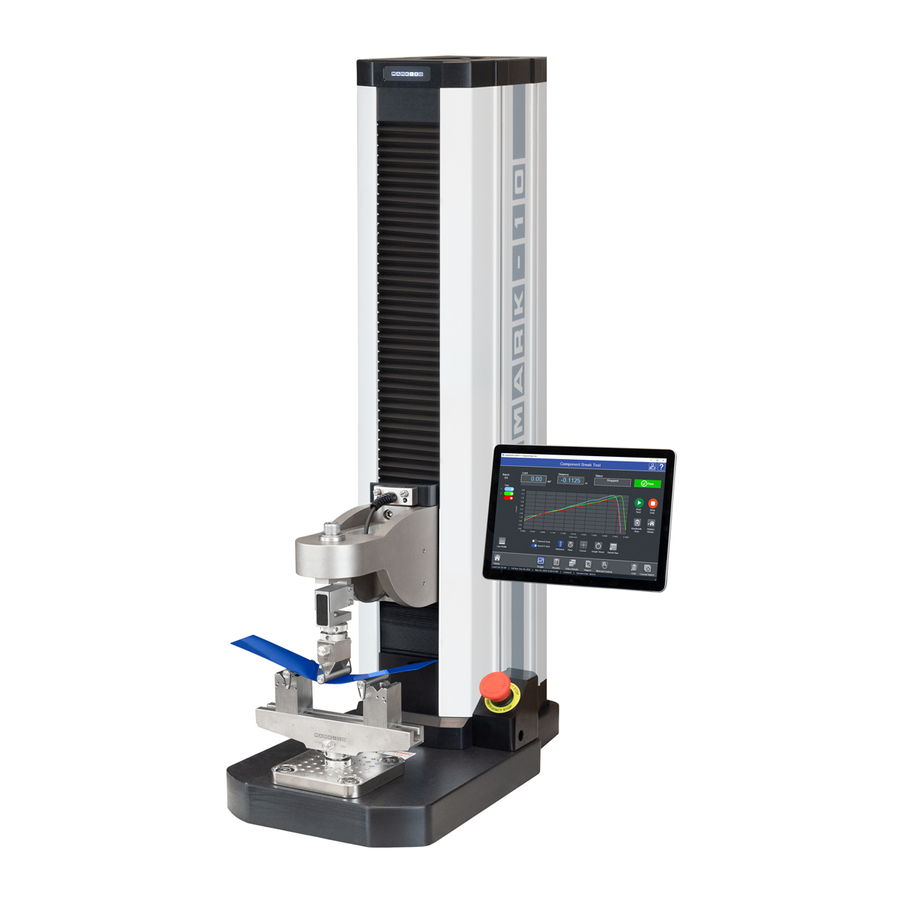
Series F Test Frames + EasyMESUR Software User’s Guide ® 1 OVERVIEW 1.1 Intended purpose Series F test frames with EasyMESUR control panels produce tension and compression loads. When combined with a force sensor, users can measure load and distance, set up a test, record, analyze, and output data. - Page 5 Series F Test Frames + EasyMESUR Software User’s Guide ® 1.2.2 Physical features Note the following physical features. The user’s guide will reference this terminology. Model F305-EM is shown below: Column Power indicator (logo illuminates when powered on) Column Upper limit Bellows switch (lower limit...
-
Page 6: Models F755 / F755S / F1505 / F1505S
Series F Test Frames + EasyMESUR Software User’s Guide ® 1.2.3 Installing the Column End Cap for F505H The end cap is shipped in a separate box within the main box for the F505H test frame. Line it up with the right end of the column, then install with the four included screws, as shown below: 1.3 Models F755 / F755S / F1505 / F1505S 1.3.1 Included items... - Page 7 Series F Test Frames + EasyMESUR Software User’s Guide ® 1.3.2 Physical features Note the following physical features. The user’s guide will reference this terminology. Model F1505-EM is shown below: Column cap Power indicator (logo illuminates when powered on) Column Limit Bellows switches...
-
Page 8: Easymesur Control Panel - Physical Features
Series F Test Frames + EasyMESUR Software User’s Guide ® 1.4 EasyMESUR Control Panel - Physical Features Note the following physical features: Boot-up indicator This LED blinks during boot- up until the EasyMESUR welcome screen appears. 7” touch display Test frame connection cable USB-C –... -
Page 9: Safety
If using a grip or fixture from a supplier other than Mark-10, ensure that it is constructed of suitably rugged materials and components. -
Page 10: Connecting Power
Series F Test Frames + EasyMESUR Software User’s Guide ® 2.2 Connecting power Plug one end of the power cord into its receptacle at the rear of the stand and the other end into a wall outlet with local earth ground (3-prong connector). Before turning on power, the following safety checks and procedures should be performed: 1. -
Page 11: Setup
Series F Test Frames + EasyMESUR Software User’s Guide ® 3 SETUP 3.1 Intended Use Series F test frames with EasyMESUR control panel are designed for tension and compression measurement applications. The test frame applies load, while a force sensor measures the applied loads. EasyMESUR displays load and position information, and includes analytical tools to help quality control, engineering, and manufacturing professionals determine the mechanical properties and quality of materials and assemblies. -
Page 12: Connections And Outputs
Series F Test Frames + EasyMESUR Software User’s Guide ® 3.5 Connections and outputs The following connections and outputs are supplied in the rear of the test frame, as shown in the illustration below: Auxiliary Limits For interfacing an external limit switch, such as an interlock for a shield door. -
Page 13: Installing Series Fs05 Force Sensors To Models F105 / F305 / F505 / F505H
Series F Test Frames + EasyMESUR Software User’s Guide ® 3.6 Installing Series FS05 Force Sensors to Models F105 / F305 / F505 / F505H To avoid overload and damage, select a force sensor with sufficient capacity to accommodate the application. Series FS05 force sensors mount directly to the crosshead. -
Page 14: Installing Series Fs06 Force Sensors To Models F755 / F755S / F1505 / F1505S
Series F Test Frames + EasyMESUR Software User’s Guide ® Grips and fixtures may be threaded onto the threaded shaft protruding from the bottom of the force sensor, for example: To avoid damage to the internal load cell or shaft, do not use tools to tighten grips or attachments onto the shaft. -
Page 15: Installing Series Fs05 Force Sensors To Models F755 / F755S / F1505 / F1505S
Series F Test Frames + EasyMESUR Software User’s Guide ® Grips and fixtures may be threaded onto the underside of the sensor. 3.9 Installing Series FS05 Force Sensors to Models F755 / F755S / F1505 / F1505S Series FS05 force sensors may be installed via the optional AC1083 adapter, as shown below: 3.10 Installing a Third-Party Force Sensor Before installing the sensor, refer to the Model PTA / PTAF user’s guide for complete instructions. -
Page 16: Installing The Easymesur Control Panel
Series F Test Frames + EasyMESUR Software User’s Guide ® 3.11 Installing the EasyMESUR Control Panel The mounting arm is pre-installed into the front right slot in the test frame column via two screws, as shown below: Loosen the knob sufficiently to slide the ball, mounted to the rear of the control panel, into the arm. Adjust the viewing angle as desired, then tighten the knob. - Page 17 The control panel will boot up automatically when the test frame is powered on. Power is indicated when the Mark-10 logo at the top of the column is illuminated. While booting up, the LED in the upper right corner of the EasyMESUR control panel will flash until the welcome screen appears.
-
Page 18: Easymesur Basics
Series F Test Frames + EasyMESUR Software User’s Guide ® 4 EASYMESUR BASICS 4.1 Evaluation Mode EasyMESUR control panels have a number of standard and optional functions. All systems are shipped in Evaluation Mode, a 160-hour period in which all available functions are temporarily enabled. At boot-up, a counter displays the number of hours remaining. - Page 19 Series F Test Frames + EasyMESUR Software User’s Guide ® EasyMESUR launches into the Home Screen, with the following selections: Open Test Recall a previously saved test. Manual Control Manually control the up and down motion of the test frame, and see live load, peak load, and live distance.
-
Page 20: Settings
Series F Test Frames + EasyMESUR Software User’s Guide ® 5 SETTINGS 5.1 Information Contains serial numbers, software and firmware versions, and other information about the equipment. The screen appears as follows: TOC ... -
Page 21: Preferences
Series F Test Frames + EasyMESUR Software User’s Guide ® 5.2 Preferences Default units of measure, date and time format, and other settings may be accessed from the Preferences screen. The screen appears as follows: TOC ... - Page 22 Delete User Files Delete all user-created files, such as tests and results. Export All Log Files Export all system log files to a USB flash drive. Only necessary if requested by Mark-10’s technical support or engineering personnel. Backup User Data and Settings Create a complete system backup file, including all settings, test files, and results files.
-
Page 23: Overload History
Series F Test Frames + EasyMESUR Software User’s Guide ® 5.3 Overload History EasyMESUR constantly monitors the force sensor, and stops the crosshead when the load reaches 120% of capacity. However, it is still possible to overload a force sensor when it is stationary by manually applying excessive force to it. -
Page 24: Optional Functions
Series F Test Frames + EasyMESUR Software User’s Guide ® 5.6 Optional Functions 5.6.1 List of Available Functions and Packages Individual Functions Model No.* Function Description EMF001-1 / -2 Distance Measurement Measure distance, with the ability to zero the reading. EMF002-1 / -2 Distance Limits Stop at user-defined upper and lower distance limits. - Page 25 Installed functions are denoted with a green checkmark. Uninstalled functions are denoted with a “padlock” icon. To activate a function or multiple functions, check the appropriate boxes. Contact Mark-10 with the list of requested functions, along with the serial number, and an Activation Code will be assigned. Type this code into the space provided, then press Enter.
-
Page 26: Manual Control
Series F Test Frames + EasyMESUR Software User’s Guide ® 6 MANUAL CONTROL Manual Control allows the user to move the crosshead up and down and observe load and distance data, without creating a test. Manual control is useful when needing to manually adjust the crosshead prior to starting a test. -
Page 27: Load And Distance Measurement
Series F Test Frames + EasyMESUR Software User’s Guide ® 6.2 Load and Distance Measurement Load Load is displayed in the unit of measurement selected in Preferences. Use the Mode button to toggle between three display modes: Load The real-time load. Peak Compression Load Maximum observed compression load. -
Page 28: Set Home
Series F Test Frames + EasyMESUR Software User’s Guide ® Maintained Mode The crosshead will move continuously after selecting the Up or Down button. Set the speed in the same manner as Momentary Mode. FollowMe Mode ® The crosshead responds to pushing or pulling on the force sensor’s load cell shaft by hand. Increasing load produces greater speeds. -
Page 29: Creating A Basic Test
Series F Test Frames + EasyMESUR Software User’s Guide ® 7 CREATING A BASIC TEST To create a basic test, press New Test on the Home screen, then select one of the following test types: Load Crosshead stops at a specified load limit. Distance / Limit Switch Crosshead stops at a specified distance limit (optional Distance Measurement function required) or limit switch. -
Page 30: Load Test
Series F Test Frames + EasyMESUR Software User’s Guide ® 7.1 Load Test The test creation process is divided into three sections: 1. Basic Settings 2. Data Collection & Results 3. Graphing 7.1.1 Basic Settings Test Direction Specify Tension (moving up) or Compression (moving down). Zero Load Zero the load value at the start of the run. - Page 31 Series F Test Frames + EasyMESUR Software User’s Guide ® Load Target The crosshead will stop when the specified load is reached. Test Speed The speed at which the crosshead travels. The speed range depends on whether the optional Low Speed Extension and High Speed Extension options are activated.
- Page 32 Series F Test Frames + EasyMESUR Software User’s Guide ® 7.1.3 Graphing Show Graph Display a graph for the test. Graph Type Select a graphing type: Continuous The graph plots one run continuously at the specified Data Collection Rate. Single Plots a single result for each run.
- Page 33 Series F Test Frames + EasyMESUR Software User’s Guide ® The most common method to plot a curve is to plot up and to the right. To achieve this trajectory, or other type of trajectory, data for each axis may be inverted to compensate for the plotting protocol mentioned above.
- Page 34 Series F Test Frames + EasyMESUR Software User’s Guide ® Press Next to save the test. The screen appears as follows: Internal storage USB flash drive storage Create new folder Search and sort Select the desired file location – internal storage within the EasyMESUR control panel’s hard drive or USB flash drive.
-
Page 35: Distance Test / Limit Switch Test
Series F Test Frames + EasyMESUR Software User’s Guide ® 7.2 Distance Test / Limit Switch Test If the optional Distance Measurement function is not installed, this test is labeled as “Limit Switch”, since the only target type is a limit switch. 7.2.1 Basic Settings Same as in a Load Limit test, except for available target types: Limit Switch... -
Page 36: Load Hold Test (Optional Function)
Series F Test Frames + EasyMESUR Software User’s Guide ® 7.4 Load Hold Test (optional function) 7.4.1 Basic Settings Same as in a Load Limit test, except for parameters which define a load hold: Load Target The crosshead will stop at this specified load and automatically adjust in either direction to maintain the load for a specified period of time. -
Page 37: Averaging Test
Series F Test Frames + EasyMESUR Software User’s Guide ® Dwell Time Specify the time the crosshead waits at a target between strokes. Lower Target Same parameters as Upper Target. 7.5.3 Data Collection & Results Same as in a Load Limit test, except for available results: Max Load The maximum load which occurred during the run. - Page 38 Series F Test Frames + EasyMESUR Software User’s Guide ® Distance Specify one of the following distance conditions: Limit Switch The crosshead will stop when it reaches the upper or lower limit switch. Distance (requires the optional Distance Measurement function) The crosshead will stop when it reaches the specified distance.
-
Page 39: Opening And Running A Test
Series F Test Frames + EasyMESUR Software User’s Guide ® 8 OPENING AND RUNNING A TEST 8.1 Favorite Tests Saved tests may be designated as favorites, for quick access when selecting Open Test from the Home screen. The screen appears as follows: The list of tests may be rearranged by using the up and down arrows. -
Page 40: Other Tests
Series F Test Frames + EasyMESUR Software User’s Guide ® 8.2 Other Tests Press Other Tests to view a complete list of all tests. The screen appears as follows: Select the desired file location – internal storage within the EasyMESUR control panel or USB flash drive. Optionally create a new folder in which to save an imported file. -
Page 41: Running A Test
Series F Test Frames + EasyMESUR Software User’s Guide ® 8.3 Running a Test Upon opening a test, the screen appears as one of the following: 8.3.1 Running a Load vs. Distance Test with Graphing This example view includes Load, Distance, a graph of Load vs. - Page 42 Series F Test Frames + EasyMESUR Software User’s Guide ® If the crosshead reaches a limit switch before reaching a non-limit switch target, the run will be marked as an “exception”. Graph The graph is displayed according to the configuration specified in the test setup. Possible configurations are as follows: Continuous Graph of Load vs.
- Page 43 Series F Test Frames + EasyMESUR Software User’s Guide ® Results Go to the Results view. Refer to the next section for instructions. 8.3.2 Running a Load vs. Distance Test without Graphing This example view includes Load and Distance, without a graph. Either the Distance Measurement option is not installed, or graphing was not enabled in the test setup.
- Page 44 Series F Test Frames + EasyMESUR Software User’s Guide ® 8.3.3 Running a Load Test without Graphing This example view includes Load only, without a graph. Either the Distance Measurement option is not installed, or graphing was not enabled in the test setup.
-
Page 45: Results (Requires The Optional Graphing & Reporting Function)
Series F Test Frames + EasyMESUR Software User’s Guide ® 8.4 Results (requires the optional Graphing & Reporting function) Press Results to view a table of results for each test run and continuous data from the most recent run. The default view is Run Results. Press either Run Results or Last Run, and switch views as needed. Data may be saved, exported, or converted into a report. - Page 46 Series F Test Frames + EasyMESUR Software User’s Guide ® The status bar, measurements, start / stop functions, and functions along the bottom of the screen are the same as in other views. 8.4.2 Last Run The table displays the reading number and associated elapsed time, load, and distance values (if the optional Distance Measurement function is installed).
- Page 47 Series F Test Frames + EasyMESUR Software User’s Guide ® 8.4.3 Report A report may be created, containing the results, graph, equipment used, and other pertinent information. Press Report to access the report creation template. The report template appears as shown at left. Create a template by filling out any of the following information: Company Name...
- Page 48 Series F Test Frames + EasyMESUR Software User’s Guide ® ^ .pdf report TOC ...
-
Page 49: Pc Control
Series F test frames can be controlled by a third-party custom software application, largely bypassing the EasyMESUR control panel. Mark-10 publishes a library of serial commands which may be used for motion control and data collection. While PC Control is active, users only have access to the Manual Control screen in EasyMESUR. -
Page 50: Command Set
Series F Test Frames + EasyMESUR Software User’s Guide ® 9.2 Command Set A list of supported ASCII commands is provided below. Note: All commands are a fixed format and do not require a terminating character. Responses from request commands are terminated with a CR-LF pair. (CR = 0xD, LF = 0xA) Command Description Example... - Page 51 TCD software (not available from Mark-10). Note: Series F test frames do not respond to Mark-10 force gauge commands which may be present in a legacy application (Mark-10 commands are denoted with a forward slash “ / “ (no quotations), followed by the commands, followed by a back slash “...
-
Page 52: Calibration
10 CALIBRATION 10.1 Force Sensor Calibration Mark-10 recommends calibrating force sensors at least once per year. Series FS05, FS06, and R07 force sensors may be calibrated while installed on a Series F test frame, or may be removed the frame and calibrated with a Mark-10 Model M5I or Model M7I indicator. - Page 53 Series F Test Frames + EasyMESUR Software User’s Guide ® Optionally configure a Calibration Reminder, in days. To save the settings and return to the Home screen without calibrating, press Save and Exit. To continue with calibration, press Save & Continue. The calibration date is intended for informational purposes only.
- Page 54 Series F Test Frames + EasyMESUR Software User’s Guide ® The force sensor can be calibrated at up to 10 points in each direction. Enter the number of calibration points for each direction (tension and compression). At minimum, the sensor must be calibrated at full scale in both directions.
- Page 55 Series F Test Frames + EasyMESUR Software User’s Guide ® Optionally load and unload the force sensor to full scale several times, then press Next. Zero the indicator associated with the master load cell. Engage the calibration fixtures, and ensure that there is no load applied to the force sensor. Then press Next. Apply the indicated compression load using the crosshead motion controls.
- Page 56 Series F Test Frames + EasyMESUR Software User’s Guide ® Configure the calibration fixtures and equipment for tension loading. Then press Next. 12. Subsequent steps are the same as in compression: Exercise the force sensor Install necessary fixtures Apply the required loads 13.
-
Page 57: Speed And Distance Calibration
For calibration instructions, refer to the indicator’s user’s guide. 10.2 Speed and Distance Calibration Mark-10 recommends verification of speed and distance accuracy once per year. Note that no adjustments may be made. Calibration is offered by Mark-10, as well as certain distributors and third- party laboratories. TOC ... -
Page 58: Maintenance & Service - Models F105 / F305 / F505 / F505H
Series F Test Frames + EasyMESUR Software User’s Guide ® 11 MAINTENANCE & SERVICE – MODELS F105 / F305 / F505 / F505H 11.1 Physical Maintenance Series F test frames should be operated in a dry and clean area. Under these circumstances the main consideration is lubrication of the ball screw and slider. - Page 59 Series F Test Frames + EasyMESUR Software User’s Guide ® 11.1.2 Slider lubrication – once per year Slider lubrication frequency should increase when used in in adverse conditions. Follow these instructions: Two people are recommended for this procedure, due to the risk of tipping. 1.
- Page 60 ® 3. Remove the base, then remove the two screws on the right, as shown below: 4. Remove the Mark-10 logo strip, then remove all screws from the side of the test frame, as shown below: 5. Locate the grease receptacle on the slider, as identified below:...
- Page 61 1. Remove the test sample from the test frame. 2. Attempt to loosen subcomponents of the test frame (ex. fasteners, brackets, etc.). All components should be firmly attached. If any looseness is detected, stop using the test frame and contact Mark-10 or a distributor for instructions. TOC ...
-
Page 62: Removing The Motor Drive Unit (Mdu)
The MDU is the self-contained location of most of the test frame’s electronics, and is designed for quick removal and replacement in the event of service or repair. If requested by Mark-10 or a distributor to remove and/or replace the MDU, follow these instructions: 1. -
Page 63: Maintenance & Service - Models F1505 / F1505S / F755 / F755S
Series F Test Frames + EasyMESUR Software User’s Guide ® 12 MAINTENANCE & SERVICE – MODELS F1505 / F1505S / F755 / F755S 12.1 Physical Maintenance Series F test frames should be operated in a dry and clean area. Under these circumstances the main consideration is lubrication of the ball screw and slider. - Page 64 Series F Test Frames + EasyMESUR Software User’s Guide ® 12.1.2 Slider lubrication As with the ball screw, periodic lubrication of the slider improves performance and increases the longevity of test frame components. Frequency depends on environmental conditions and usage. Follow these instructions for proper slider lubrication: 1.
-
Page 65: Removing The Motor Drive Unit (Mdu)
The MDU is the self-contained location of most of the test frame’s electronics, and is designed for quick removal and replacement in the event of service or repair. If requested by Mark-10 or a distributor to remove and/or replace the MDU, follow these instructions: 1. -
Page 66: Accessory Installation
When a shield is used, the standard emergency stop switch is located within the enclosure, preventing its use during a test. An external limit switch is, therefore, included with Mark-10 shields. For all Series F test frames, the connector must be installed in the rear of the MDU. It may be factory- installed if ordered at time of order (reference part no. - Page 67 Series F Test Frames + EasyMESUR Software User’s Guide ® 3. Remove the back panel from the MDU housing with the four screws, highlighted below: 4. Route the two wires from the rear of the connector through the hole, as shown below: 5.
-
Page 68: Separating The Column From The Base / Column Extension Installation - F105 / F305 / F505 / F505H
Series F Test Frames + EasyMESUR Software User’s Guide ® 6. Install the connector to the housing by inserting the spacer over the body of the connector, then tightening the nut, as shown below: 7. Reassemble the MDU and reinstall, as instructed in earlier sections. 8. - Page 69 User’s Guide ® 13.2.2 Retrofitting a Mark-10 AC1094-1 / -2 / -3 single column extension (optional) If a single column extension is ordered upfront, it is pre-installed at the factory and shipped assembled. To retrofit in the field, follow these instructions: 1.
- Page 70 Series F Test Frames + EasyMESUR Software User’s Guide ® 3. Attach the top flange to the bottom of the test frame column utilizing the 6 supplied screws, as shown in the image below: 4. Position the test frame vertically and reinstall the sheet metal covers, as shown below: Vertical column extensions present an increased tipping hazard.
-
Page 71: Installing A Double Column Extension - F105 / F305 / F505
Series F Test Frames + EasyMESUR Software User’s Guide ® 13.3 Installing a double column extension – F105 / F305 / F505 Models AC1095-1 / -2 / -3 column extensions are shipped fully assembled. To mount the test frame to the assembly, locate the 6 thru holes, match them up to the corresponding threaded holes on the underside of the frame, and install the screws. -
Page 72: Updating Software And Firmware
14.1 Update EasyMESUR Press Update EasyMESUR. The screen appears as follows: The file will be supplied by Mark-10 or a distributor. Save the file to a PC or USB flash drive, browse to it, then press Start Update. Do not power off the test frame or disconnect the EasyMESUR control panel until the update is complete. -
Page 73: Update Test Frame Firmware
Select “Use latest firmware version ( )” to install the latest available firmware version associated with the current EasyMESUR version. Otherwise, browse to the desired location and install another firmware file. For best performance, Mark-10 strongly recommends using the latest firmware version. TOC ... -
Page 74: Specifications & Dimensions
Series F Test Frames + EasyMESUR Software User’s Guide ® 15 SPECIFICATIONS & DIMENSIONS 15.1 Specifications F105 F305 F505 F505H F755 F755S F1505 F1505S 100 lbF 300 lbF 500 lbF 750 lbF 1,500 lbF Load capacity*: [0.5 kN] [1.3 kN] [2.2 kN] [3.4 kN] [6.7 kN]... -
Page 75: Dimensions In [Mm]
Series F Test Frames + EasyMESUR Software User’s Guide ® 15.2 Dimensions IN [MM] 15.2.1 Models F105 / F305 / F505 TOC ... - Page 76 Series F Test Frames + EasyMESUR Software User’s Guide ® 15.2.2 Model F505H TOC ...
- Page 77 Series F Test Frames + EasyMESUR Software User’s Guide ® 15.2.3 Models F755 / F755S / F1505 / F1505S F755 F755S F1505 F1505S 50.85 33.39 51.35 33.89 [1291.6] [848.1] [1304.3] [860.9] 8.13 – 40.13 8.13 – 22.33 8.13 – 40.13 8.13 –...
- Page 78 Software User’s Guide Mark-10 Corporation has been an innovator in the force and torque measurement fields since 1979. We strive to achieve 100% customer satisfaction through excellence in product design, manufacturing and customer support. In addition to our standard line of products we can provide modifications and custom designs for OEM applications.
Need help?
Do you have a question about the F Series and is the answer not in the manual?
Questions and answers