ALFAMATIC Press-Right User Manual
For electric press
Hide thumbs
Also See for Press-Right:
- User manual (53 pages) ,
- Installation manual (21 pages) ,
- User manual (42 pages)
Table of Contents
Advertisement
Quick Links
Advertisement
Table of Contents

Related Manuals for ALFAMATIC Press-Right


Summary of Contents for ALFAMATIC Press-Right
- Page 1 U S E R M A N U A L RESS IGHT FOR ELECTRIC PRESS • User manual...
-
Page 3: Table Of Contents
Absolute and relative positions .................. 6 Control of position-force curve................... 7 Installation of Press-Right ..................9 Getting started ....................10 The keyboard of Press-Right ................... 10 First approach ......................10 Create a job ......................10 Set the movement ....................11 Set the view ...................... - Page 4 11.1 Additional force transducer ..................29 11.2 Tool recognition ...................... 29 12 Password ......................30 13 Computer connection ..................31 13.1 Connection via USB port ..................31 13.3 Connection via LAN port (Ethernet) ................. 31 14 Field bus ......................33 14.1 Organization ......................
-
Page 5: General Information
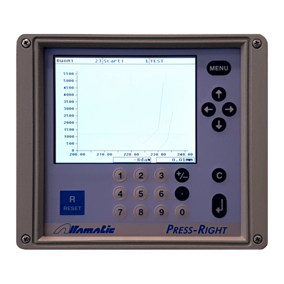
1 General information Press-Right is a monitor and measuring device that is connected to a press and monitors the quality of productive processes. Being interfaced with a displacement transducer and a load cell, it continuously monitors its positions and instantaneous force. -
Page 6: Absolute And Relative Positions
Press-Right may set both the absolute and the relative positions. In order to measure the contact point on the manufactured piece, Press-Right use the force transducer: when the force measured exceeds the Force for contact detection value, the relative zero point is set. -
Page 7: Control Of Position-Force Curve
Control of position-force curve Press-Right enjoys different functions. The curve monitoring is performed by a tolerance range (chapter 6) and its limits (chapter 0). The limits are the following: minimum and maximum force, minimum and maximum position; they can be set or excluded and they monitor the maximum value obtained during the production. - Page 8 Press-Right also monitors the cylinder return at the end of the production process. Such return may result from the exertion of a specific force (stop force) or at a specific position (final position).
-
Page 9: Installation Of Press-Right
2 Installation of Press-Right For the installation of the device on the machine, please refer to the specific manual. -
Page 10: Getting Started
To turn the device on use the key on the rear side. When it is pressed, after a few seconds, the display turns on and the graph appears. The keyboard of Press-Right If you press the menu key, the items that make up the main menu are displayed. To select... -
Page 11: Set The Movement
To create a job: • press the menu key • press the Jobs management item • press the Create a new job item. • Enter the name that identifies the job (example TEST 1) and press the enter key. Set the movement Note: in the rest of this manual, when it is indicated, for example, to select the command Jobs management >... - Page 12 The Show measured values item displays the values measured during the last cycle. The Tools allows the modification of the instrument configuration and the possibility to move the cylinder manually. The item Piece counter is used to reset the counter of processed pieces. The item Part number allows you to enter the identification number of the piece being processed.
-
Page 13: The Job
4 The JOB The Press-Right stores all the settings (parameters, band and counters) relating to the various jobs in an internal memory. Each group of settings is called “Job”. Each job has its own name. In the main menu there is the item Jobs management. Through this menu it is possible to choose a job among those present, create a new one, or delete the job in use. -
Page 14: Job Counters
Managing the automatic selection of jobs as an external user When the automatic job selection is activated, the Press-Right prepares the selectable jobs. These jobs are initially empty. To make an empty job usable, access the Job management>... -
Page 15: Channel Management
4.12 Channel management Up to six force transducers can be connected to the Press-Right to control as many displacement-force curves. While each force transducer detects the force of a channel, the position transducer is only one in common to all channels. It is possible to exclude one or more channels from the control thanks to the CONFIGURE OPERATION>... - Page 16 It does not measure The additional check is not performed. Measure at the start The additional check is carried out when the instrument receives the START command. Measure at stop The additional check is carried out when the tool wants to command the stop and the piece is good.
-
Page 17: Parameters
5 Parameters Note: in general, the parameters set equal to zero will be ignored by the instrument. Motion management Once a new job has been created, the movement of the cylinder must be defined. The motion profile parameters are as follows and can be found in the Edit job > Movement management menu. - Page 18 Maximum force limits, maximum altitude limits, initial altitude limits and checkpoints can be set. Note: Control limits, set equal to zero, are not used. Contact position limits They control the contact dimension of the machining. For a piece to be classified as good, the measured contact height must be above the minimum contact height limit and below the maximum contact height limit.
-
Page 19: Check Points
Limits with machining without mechanical stop In this case the force limits are not very useful other than to check that the force does not exceed the maximum force supported by the workpiece. The force check must be performed with the band or check points. Dimension limits can be used to verify that the final assembly size is actually what is required. - Page 20 Do not use waste basket Disable the control of the waste basket in the job.
-
Page 21: The Tolerance Bande
6 The tolerance bande The band is used to control the curve and consequently to control the quality of the piece. The band consists of two lines called the upper edge and lower edge. For the piece to be classified as good the points representing the curve cannot be above the top edge, and they cannot be below the bottom edge. -
Page 22: Rejected Piece
When a scrap piece is detected, the tool stops, preventing the execution of new pieces. In the standard configuration, to re-enable the instrument, RESET must be performed. If the work has several phases, the Press-Right can request confirmation of the rejection. Causes rejection A piece can be good or bad. -
Page 23: Rejected Management
For instance, it is possible to sort reusable scraps from not recyclable materials. When a special scrap is detected, Press-Right activates the second scrap port ad count the piece separately. This way, it is possible to know whether the pieces are rejected by mistake by the operator. -
Page 24: The Tools Menu
Counters and self-verification Press-Right can be set up so that, at fixed intervals, the tool must be replaced, the transducers calibrated and the self-verification system monitored. The self-verification function is described in chapter 4.13. - Page 25 With this command the cylinder descends until it touches the piece. The feed speed and contact force is set in the cylinder configuration menu.
-
Page 26: Intrument Configuration
9 Intrument configuration In general, when the Press-Right is supplied already connected to the machine, it is not necessary to configure it. Thanks to the many configuration options, the Press-Right can adapt to your needs. To configure the Press-Right, access the TOOLS> CONFIGURE menu. -
Page 27: Automatic Selection Of Jobs
By activating this option, the Press-Right will not increase the piece counter if it has not measured a starting position, that is, if it has not met the piece. DIFFERENT WASTE CLASS IN EVERY JOB By activating this option, each job has a different waste management (chapter 7). -
Page 28: Diagnosis
10 Diagnosis The diagnostic function enables: the visualization of the input status, the visualization and the forcing of outputs, the calibration of the transducers. Given the complexity of these operations, we recommend the use of qualified personnel. The activated inputs and outputs that are highlighted with a black rectangle. To force the outputs, move the cursor with the keys on the desired output and press... -
Page 29: Special Configurations
It is possible to provide the instrument with a small force transducer for greater precision in processes that require reduced forces. The Alfamatic pressure transducer has been designed to withstand the maximum force that can be exerted by the cylinder. -
Page 30: Password
12 Password Press-Right can store a list of users with their identification codes. The identification code is a four or five-digit code. The last three digits are never displayed, and serve as a password. Each user can define permissions, that is, the functions that can be accessed to. -
Page 31: Computer Connection
13 Computer connection Press-Right can be connected to a computer. It is possible to connect the tool to the computer via USB or the Ethernet port (optional). The tool is provided together with the Winscope software, enhancing the tool capabilities. - Page 32 Select the tool to which the IP address is to be assigned in the list that is shown. If the list is empty, monitor the status of the firewall in your computer, if any. The firewall can be disabled in the Windows monitor Panel. If you cannot find the tool to be set up, just turn it off, reload the list and see which one is missing.
-
Page 33: Field Bus
14 Field bus The Press-Right instrument can communicate via Modbus TCP field buses (standard), PROFINET or EtherNet/IP (optional). 14.1 Organization The instrument has a list of registers that can be read or written via fieldbus communication. Each register has an address. From the field bus it is possible to access the registers by indicating the address of the same. - Page 34 The default content of these words is the following: 14.3.1 Access via address / data 14.3.1.1 Initialization Load the value 0x00 into CTRL_OUTPLC Wait for CTRL_INPLC to contain 0x00 14.3.1.2 Reading a 16-bit register Load the register address into INDEX_OUTPLC Load the value 0x40 into CTRL_OUTPLC Wait for CTRL_INPLC to contain 0x10 Read the value from PV_INPPLC...
- Page 35 To install the GSD file in the library, select Tools> Device Description File Management. You can find it in the library under Additional field devices> PROFINET IO> General> Alfamatic> PressRight. The name and address of the device is set by TIA: Open the TIA, under "Online access"...
-
Page 36: Organization Of Registers
15 Organization of registers 15.1 Command execution By writing in the CONTROL_WORD_OUTPLC the press is controlled. The command must be written until the STATUS_WORD_INPLC command busy bit becomes high; at this point it is necessary to write zero in CONTROL_WORD_OUTPLC. Regardless of whether the command involves a movement or not, as long as the command is present, bit 11 of STATUS_WORD_INPLC will remain high. -
Page 37: Logs Table
The high byte of the register contains the first character of the pair. The low byte of the register contains the second character of the pair. Below is an example of reading the name of the job that we assume to be "Job 2": ASCII Codes: 0x4A 0x6F... - Page 38 ForceAct Current force INT32 6 Read only Control Word 0 no command UINT16 24 Write Write 1 to reset fault Write 2 to select job by text code (&45) Write 3 to select job by name (&45) Write 4 to set the part number (&45) Write 5 to save data on persistent memory Write 7 to reset flags (from version 1.58) Write 8 to delete the curves in memory...
- Page 39 JobNumNOK Number of rejected pieces (to reset use control UINT32 99 Read only word = 18) MaxNumOK Maximum number of good pieces UINT32 101 Write/read PartNumber Code STRING 28L 103 Read only Read only InstrumentName Name of the instrument STRING 15L 200 Read only DecimalsY Number of decimals digit of force values...
- Page 40 PeakForceMin Value minimum of reached force UINT16 1029 Write/read PeakForceMax Value maximum of reached force UINT16 1030 Write/read InitPosMin Value minimum of conctact position UINT16 1031 Write/read InitPosMax Value maximum of conctact position UINT16 1032 Write/read CP1par1 First value of check point 1 UINT16 1033 Write/read CP1par2...
- Page 41 CP4par5 Fifth value of check point 4 UINT16 1052 Write/read CP5par1 First value of check point 5 UINT16 1053 Write/read CP5par2 Second value of check point 5 UINT16 1054 Write/read CP5par3 Third value of check point 5 UINT16 1055 Write/read CP5par4 Fourth value of check point 5 UINT16...
- Page 42 BIT7: LOW SPEED Issue B BIT0: MAX POSITION UINT16 2001 Read only BIT1: MIN POSITION BIT2: MAX CONTACT BIT3: MIN CONTACT BIT4: MAX CHECK POINT BIT5: MIN CHECK POINT BIT6: TEST INPUT 2 BIT7: TEST INPUT 3 Issue C BIT4: MAX FORCE UINT16 2002 Read only BIT5: MIN FORCE...
-
Page 43: Description Of Check Point Registers
15.5 Description of Check Point registers The check points are described by five different parameters: CPxPar1, CPxPar2, CPxPar3, CPxPar4, CPxPar5. The function of these parameters varies according to the type of check point. With check points, for each piece worked, the instrument measures one or two values. These values are available in the CPxValueA and CPxValueB registers. - Page 44 15.5.5 Registers for check point setpoint Register Function Data type CPxPar1 Quota attivazione setpoint 1 Position CPxPar2 Quota attivazione setpoint 2 Position CPxPar3 Quota attivazione setpoint 3 Position...
-
Page 45: Specifications And Troubleshooting
Depth: 240 mm 16.5 Characteristics of the instrument The Press-Right detects the position-force curve during work. Manages and controls the cylinder speed profile. Work on a continuous tolerance band by controlling the entire position-force curve. Check the height and the peak force values. - Page 46 All control parameters are stored in 200 independent and selectable jobs. Advanced user management with personal passwords and permissions. It is possible to connect the Press-Right to the computer and, thanks to the WinScope program, to save the curves, modify the settings, perform statistical analysis, print the data.
Need help?
Do you have a question about the Press-Right and is the answer not in the manual?
Questions and answers