Table of Contents
Advertisement
Quick Links
Advertisement
Table of Contents

Related Manuals for ALFAMATIC Check Point 4


Summary of Contents for ALFAMATIC Check Point 4
- Page 1 Check Point 4 Version 1.24 and later User and installation manual Jan. 19, 2024...
-
Page 3: Table Of Contents
Introduction ..........................4 Operation of the instrument ......................4 Notes ..............................4 Password ............................. 4 Introduction on the use of the CHECK POINT ..................5 Entering a value ..........................5 Menu Description.......................... 6 Max value reached ..........................6 Result ..............................6 Good pieces ............................ -
Page 4: Introduction
You cannot accidentally change configuration values without entering the configuration password. A second password can be entered to prevent changing control parameter values. Password management is possible through the Check Point 4 setup program. 1.3 Password The configuration of the instrument is protected by the configuration password which is initially 9724. -
Page 5: Introduction On The Use Of The Check Point
Management of these passwords is possible through the Check Point 4 setup program. Memory formatting is protected by password 9724, which cannot be changed. When you enter a password, the instrument remains unprotected for one minute or until you press RESET out of the menus. -
Page 6: Menu Description
2 Menu Description If you press ENTER, the display will show the menu, which you can scroll through with the up and down arrow keys The following paragraphs show the menu items with a description of their function. To change the operating parameters, press the ENTER key. -
Page 7: Output Value N
2.8 Output value n This item allows you to set the threshold value for the activation of the relative output. The deactivation of the same output will occur when the value falls below the threshold minus the hysteresis value V.HYSTERESIS 2.9 Configuration This item gives access to a submenu that allows configuration of the instrument. -
Page 8: Configuration Menu
3 Configuration menu In the configuration menu you can set up the instrument for your needs. The items that make up this menu are listed in the following paragraphs. To change the configuration values, the configuration password is required (chap. 1.3). 3.1 Start value This item reports the value of the threshold. -
Page 9: Introduction To Installation
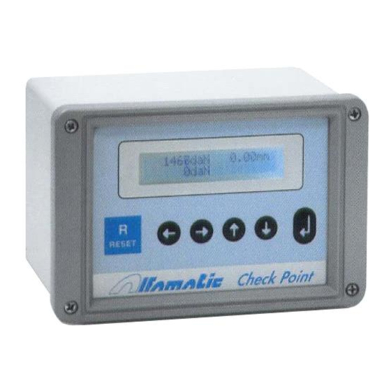
4 Introduction to installation This manual describes the steps required to connect the CHECK POINT to the machine and to make it operational. The CHECK POINT is powered by 24VDC. Check the supply voltage before connecting the instrument. Figure 4.1 Features of the instrument The CHECK POINT has two operating conditions WAIT and MEASURE. -
Page 10: Inputs And Outputs
4.1.5 END The end determines the end of the measure; the end does not coincide with the stop. Ending will lead to the stop of the measurement. The measurement will be terminated when the measured value falls below the programmable value minus the value . - Page 11 Useful for connecting the press down solenoid valve. WORKING Activated during measurement. BOOSTER/CONTACT Triggered when the start value is exceeded. This signal is used to control the working stroke of Alfamatic cylinders. CLOSE THE DOOR. Mobile protection closing command. OPEN THE DOOR Mobile protection opening command.
-
Page 12: Electrical Connections
5 Electrical connections Please read these notes: Always check the supply voltage required by the instrument before wiring the instrument. This manual refers ONLY to the version with CP4CPU2 and CP4BUS2 electronic boards. Check the wording on the boards themselves. This tool is not (and could not be) a safety device: the movement of the machine must be entrusted to elements external to it. -
Page 13: Wiring Instructions
Signal Jumper Resistive bridge 2mV/V, power supply 10 Vdc. J10 absent One-way. J11 absent J12 inserted J13 absent J14 absent J15 position A J16 position B J17 position A Resistive bridge 2mV/V, power supply 10 Vdc. J10 absent Bidirectional. J11 absent J12 absent J13 absent J14 position B... - Page 14 Figure 5.3.1 Power supply terminal block (X24) 24 VDC power supply. Name Clamp Description 0VDC X24.1 Negative power supply +24VDC X24.2 Positive power supply 5.3.2 Input and output terminal block (X1) Inputs for dry contact signals or with 24 VDC PNP transistor output. PNP outputs for 24 VDC consumers.
- Page 15 5.3.3 Encoder terminal block (X2) Name Clamp Description Phase Z X2.1 Zero mark signal Phase A X2.2 PHASE A signal Phase B X2.3 PHASE B signal X2.4 Encoder power supply X2.5 Encoder mass X2.6 Shielded cable braid DAC1 X2.7 DAC2 X2.8 Encoder power supply: 5 VDC ±20% or 12 VDC...
-
Page 16: Assembly Instructions
To position the encoder in the correct way, you must first reset the offset and then follow the instructions below: 5.5.1 For Alfamatic MOP-type presses. Turn on the instrument and remove the cover that covers the encoder the rack and the top dead center limit switch by unscrewing the two screws. - Page 17 Lower the cylinder with the lever and return it to top dead center: at this point the instrument should display a negative altitude of a few millimeters. 5.5.2 For standard Alfamatic presses First press the emergency mushroom on the press, turn on the instrument, and open the top cover of the rack block, which is closed by two self-tapping Phillips-head screws.
-
Page 18: Configuration Program
Open the update file with the extension .atm Wait for the end of the transfer. Note: To update the instrument, the update file is required to be requested from Alfamatic. 6.2 Instrument setup The configuration of the instrument is stored in the profile. The profile can be saved, uploaded,... - Page 19 The following figure shows the initial configuration of the instrument as it is set at the factory: Figure...
Need help?
Do you have a question about the Check Point 4 and is the answer not in the manual?
Questions and answers