Table of Contents
Advertisement
Quick Links
Advertisement
Table of Contents

Related Manuals for ALFAMATIC Visual Point


Summary of Contents for ALFAMATIC Visual Point
- Page 1 Visual Point Version with VP2STEP1 card Installation manual Sep. 26, 2019...
-
Page 3: Table Of Contents
Introduction..........................4 Important notes for installation ...................... 4 Dimensions ............................5 Implementing VISUAL POINT....................7 Operating of the instrument ......................7 Information for connection to an external controller (PLC) ............8 Wiring instructions........................... 9 Typical connection.......................... 14 Instructions for assembling the instrument with cabinet............15 Switching on the instrument ...................... -
Page 4: Introduction
1 Introduction This manual describes the operations necessary to connect the machine to VISUAL POINT. There are two versions of VISUAL POINT: for external mounting and for panel mounting. The panel version is only available with 24VDC power. The external mounting version is available in versions: 24VDC or 100-240VAC. -
Page 5: Dimensions
1.2 Dimensions All dimensions in millimeters. Panel mounting To the depth indicated, you have to add the dimension of the teminal blocks and of cables whith minimum lenght of 55mm Hole dimensions:... - Page 6 External mounting To the depth indicated, you have to add the dimension of cables whith minimum lenght of 80mm...
-
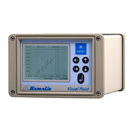
Page 7: Implementing Visual Point
Picture 2 2.1 Operating of the instrument Attention: the VISUAL POINT is not (and could not be) a safety device: the descent of the press must be entrusted to external elements. The VISUAL POINT synchronises the descent for its operation. The GO Output is usually connected serially to the chain of the cylinder descent. In... -
Page 8: Information For Connection To An External Controller (Plc)
2.2 Information for connection to an external controller (PLC) To connect the VISUAL POINT to a PLC, the latter must have PNP positive logic. The inputs and outputs of the instrument are opto-isolated from the instrument’s control electronics. The power supply of the instrument’s inputs and outputs must be the same that powers the inputs and outputs... -
Page 9: Wiring Instructions
2.3.2 Serial port terminal (CONN1) Only present in version with cabinet for external mounting. On the back of the VISUAL POINT is a D-Sub 9-male for the RS232 serial connection. The connector pin-out is as follows: Pin 2: RX input line of Visual Point. - Page 10 2.3.3 Serial Port terminal (X2) Only present in version for panel mounting. On the back of VISUAL POINT for panel mounting is the X9 terminal block to connect serial RS232. The connector pin-out is as follows: Name Terminal Function X9.1 Do not use X9.2...
- Page 11 Input functions: Function Description START Request for new cycle start T.D.C. “Top dead point” signal, used to reset for a new cycle and in AND with the zero notch of the encoder for the zero of the absolute positions RESET Re-enables the instrument after a reject (rejects basket) ENABLE Start enable...
- Page 12 Force or position trigger. See Chapter 2.8 PULLUP Command for return cylinder. TANK Segnale chiusura serbatoio del cilindro Alfamatic tipo PK RETURN Enable return of cyinder 2.3.6 Encoder and 0-10V input terminal block (X12) An incremental encoder and a 0-10V signal can be connected to the X12 terminal block. A 12VDC power supply is available for the encoder.
- Page 13 Name Terminal Function X11.1 Positive input X11.2 Negative input X11.3 Screened wire sheath X11.4 +10V X11.5 Power (60mA max) It is extremely important for the end of the wire of the load cell which is not covered by a sheath to be as short as possible. 2.3.8 Analog output terminal block (X10) Name Terminal...
-
Page 14: Typical Connection
2.4 Typical connection Wiring an encoder ELCIS and a load cell AEP: picture 3... -
Page 15: Instructions For Assembling The Instrument With Cabinet
2.5 Instructions for assembling the instrument with cabinet picture 4 To open the container with VISUAL POINT unscrew the four screws in the corners of the back and front panel. Dismantle the groups of terminal blocks. Pull out the electronic boards from the front (Figure 10). -
Page 16: Setpoint Output
2.8 SETPOINT output The VISUAL POINT SETPOINT has an exit which is normally activated when the share is measured starting (see user manual) and is off when the value of arrest. This can be used to start the phase of work, after the phase approach.
Need help?
Do you have a question about the Visual Point and is the answer not in the manual?
Questions and answers