ALFAMATIC PRESS-RIGHT User Manual
For electric cylinder
Hide thumbs
Also See for PRESS-RIGHT:
- User manual (53 pages) ,
- Installation manual (21 pages) ,
- User manual (43 pages)

Subscribe to Our Youtube Channel
Related Manuals for ALFAMATIC PRESS-RIGHT


Summary of Contents for ALFAMATIC PRESS-RIGHT
- Page 1 USER MANUAL RESS IGHT For electric cylinder • User manual Issue 2 - August 8, 2023...
-
Page 3: Table Of Contents
Rejected piece ......................7 Traction cycle ......................7 Installation Press-Right ..................8 How to start ......................9 Press-Right user interface ..................9 First approach ......................9 Create a job ......................9 Set the movement ....................10 Set the view ......................10 The main menu ....................... - Page 4 Verification ......................25 Codes of the job ...................... 25 Measured values ....................26 The measured value page ..................26 Analysis cursor ......................26 10 The tools menu ....................27 10.1 Display options ......................27 10.2 Manual moving ......................27 11 Instrument configuration ..................29 11.1 General options .......................
-
Page 5: General Informations
1 General informations Press-Right is a control and measurement instrument which, when connected to a press, guarantees the quality control of the production processes. Interfaced to a position transducer and a load cell, it continuously detects the position and the instantaneous force. -
Page 6: Absolute And Relative Positions
The positions referred to the zero of the cylinder are called absolute positions. The positions referred to the contact position on the piece are called relative positions. The Press-Right can use both absolute and relative positions. The load cell is used to detect the contact position: when the force measured by the load cell exceeds CONTACT DETECTION a programmed value, the position values is set to zero. -
Page 7: Control Of The Position-Force Curve
In practice, the Press-Right controls the curve through a tolerance range, check points and limits. The tolerance range positioned around the sample curve is such that if the curve obtained from the current machining does not pass within this range, the piece is rejected. -
Page 8: Installation Press-Right
2 Installation Press-Right To install the instrument on the machine, consult the specific manual. -
Page 9: How To Start
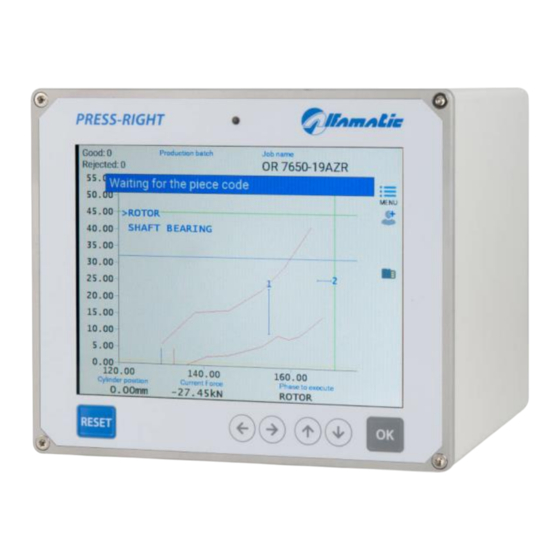
3 How to start This chapter will walk you through the basics of programming and using the Press-Right instrument. To better illustrate the operations, it is advisable to carry out the tests in practice. Figure2 To turn on the instrument there is a button on the back. When it is pressed, after a few seconds, the display lights up and the graph appears: 3.1 Press-Right user interface... -
Page 10: Set The Movement
To create a job: • Touch the menu button • Touch the JOBS LIST item • Touch the CREATE A NEW JOB item • Enter the name that identifies the job (example TEST 1) and press the enter key. Note: in the rest of this manual, when it is indicated, for example, “JOBS LIST > CREATE A NEW JOB”... - Page 11 The item RESET COUNTERS is used to reset the counters of processed pieces. When the batch number is managed, this menu will be replaced by the NEW PRODUCTION BATCH menu which allows the batch number to be entered. This number will be stored together with the curve. The PART NUMBER item allows the insertion of the identification number of the piece being processed.
-
Page 12: Jobs
4 Jobs The Press-Right memorizes all the settings (parameters, tolerance range, limits and counters) relating to the various jobs in an internal memory. Each group of settings is called Job. Each job has its own name. JOBS LIST item is present in the main menu. Through this menu it is possible to choose a job among those present, create a new one, or delete the job in use. -
Page 13: Selection Of A Job Via Fieldbus
4.6 Selection of a job via fieldbus It is possible to select the job to be used via the fieldbus in three different ways: via the job name, via the identification code or via an index number. 4.6.1 Selection from fieldbus by name To select a job, first write the code of the desired job in the string buffer at the address 45, then write command 3 in the CONTROL_WORD_OUTPLC. -
Page 14: Job Counters
4.11 Job counters Each job has a piece counter. To access the counter options, select the menu EDIT JOB > SCHEDULING. In this menu it is possible to reset the piece counter or choose a maximum number of pieces to block the instrument. - Page 15 The phases will be performed automatically in sequence. If you want to carry out a phase individually out of sequence, select the Do not perform the phases in sequence option in the TOOLS > SETUP > JOBS SELECTION menu. In this case it is not possible to change the phase that will be performed from the menu. It is also possible to have a single phase repeat several times by activating the Phase repeat options in the TOOLS >...
-
Page 16: Parameters
5 Parameters After creating a new job, the first thing to do is to set the job options in the EDIT JOB > PROPERTY AND OPTIONS menu. Once this is done, it is possible to set the operating parameters. Note: In the jobs the parameters set equal to zero will be ignored by the instrument. 5.1 Movement management The movement profile parameters are the following and can be found in the EDIT JOB >... -
Page 17: Checkpoints
Contact position limits They control the contact dimension of the working. For a part to be classified as good, the measured contact dimension must be above the minimum contact dimension limit and below the maximum contact dimension limit. Peak Position limits They control the maximum position reached during machining. - Page 18 Check force Measure and control the force at a pre-set position. This check point is also useful for having a discrete value at the end of pressing to be displayed or sent via fieldbus. Check position Measure and control the position at a pre-set force. This check point is useful for checking deformation at a pre-set load.
-
Page 19: Job Options
The piece code can also be set via a barcode scanner. To use this option, it is necessary to activate the Part number management option in TOOLS > SETUP > VISIBLE OPTIONS menu. Contact Alfamatic to find out which barcode readers are compatible with the instrument. Save curves of pieces good Save the curves of the good pieces on the internal flash memory. - Page 20 Save curves Activates the saving of the curves in the internal memory of the instrument. Save a good curve every If you only want to save some curves, with this parameter you can set every how many pieces you want the curve to be saved.
-
Page 21: The Tolerance Range
7 The tolerance range The tolerance rage is used to control the curve and consequently to control the quality of the piece. The tolerance rage consists of two lines called the upper border and the lower border. For the piece to be classified as good the points representing the curve cannot be above the upper edge, and cannot be below the lower edge. -
Page 22: Remove The Tolerance Range
7.3 Remove the tolerance range To eliminate the tolerance range use the EDIT JOB > TOLERANCE RANGE > DELETE menu. -
Page 23: Rejected Pieces
If the job has multiple phases, the Press-Right can request confirmation for the rejected. If the tolerance band is not reached by the curve and if the minimum quota limit is not present, the piece is signaled as reject due to the minimum quota not being reached. -
Page 24: Rejected Management
For example, it is possible to separate recoverable rejected from unrecoverable rejected. When there is a special reject the Press-Right activates the second reject signal and counts the piece separately. In this way it is possible to know, for example, how many pieces are rejects due to operator error. -
Page 25: Verification
8.7 Verification With this command it is possible to configure the self-verification of the job. 8.8 Codes of the job In this menu it is possible to indicate the job name, the selection index and which part of the barcode identifies the job code. -
Page 26: Measured Values
9 Measured values The Press-Right stores the displacement-force curve and measures some quantities that can be controlled thanks to the limits. The last curve can be analyzed with the analysis cursor. The quantities measured can be displayed at the end of each process. -
Page 27: The Tools Menu
This option doesn't work with phases. Light up the working area This option is available if a Press-Right output is configured to control the work area light. Displays the status of the command signals By activating this option, the status of the inputs and outputs is displayed above the graph. - Page 28 ENABLE MANUAL MOVEMENT With this command you can use the arrow buttons to move the cylinder. In the manual movement, the first section takes place very slowly, then the speed increases. If the cylinder is under stress the speed will be limited. GO TO POSITION With this command it is possible to move the cylinder to a known position.
-
Page 29: Instrument Configuration
By activating this option, the Press-Right is blocked and enabled by the supervision system connected via fieldbus. Wait for computer connection By activating this option, the Press-Right does not allow the machining of the pieces if it is not connected to the WinScope program. Count the piece when it senses a force By activating this option, the Press-Right will not increase the piece counter if it has not measured an initial position. -
Page 30: Job Selection
If several load cells are connected to the instrument, activating this option will use a different cell for each phase. This option allows you to connect up to four identical presses working in sequence one after the other to a single Press-Right. 11.2 Job selection These options modify the method used by the instrument to automatically select jobs and phases. -
Page 31: Diagnosis
(outside the menus). 12.1 Firmware version The Press-Right has several microprocessors inside. To find out the version of the software contained in the microprocessors, it is possible to view the diagnosis window TOOLS > DIAGNOSIS. -
Page 32: Special Configurations
13 Special configurations The Press-Right tool is very versatile. Thanks to Alfamatic's years of experience in pressing, the instrument is set up to solve the most varied customer needs. In order not to unnecessarily complicate the use of the instrument, these functions are hidden and must be made visible manually in the instrument configuration. -
Page 33: Management Of Supplementary Controls
In practice, the outcome of the machining can be conditioned by the logic status of three inputs. This logical state can be checked at various times during the working. For additional control number 1, the Press-Right can also activate an output before carrying out the control and, after a pre-set time, read the state of the input. - Page 34 13.4.4 Automatic selection of work with tool To automatically select the job according to the tool mounted on the press, activate the relative option in the TOOLS > SETUP > JOB SELECTION menu.
-
Page 35: Data Storage
14 Data storage The Press-Right is able to memorize the production data in the internal memory. In practice, for each piece produced, a file is created which contains the following information: • The recorded force-displacement curve. • The job settings used when recording the curve. -
Page 36: Password
The admin user cannot be deleted and has full permissions. To change the password, you need to know the old password or, if it has been lost, you need to contact Alfamatic to send him the code that appears in the old password entry window. The default administrator password is 9724. -
Page 37: Calibration
16 Calibration The calibration operation must be performed by trained and qualified personnel. To calibrate the transducers connected to the Press-Right you need to access the TOOLS > DIAGNOSIS menu. For each transducer, the raw output value from the converter and the real value of the measured quantity are shown. -
Page 38: Connection To Computer
17 Connection to computer The Press-Right can be connected to a computer. It is possible to connect the instrument to the computer via USB port or LAN (Ethernet) port. WinScope program is supplied together with the instrument, through which the potential of the instrument is extended. - Page 39 Choose the instrument you want to assign the IP address to from the list that appears. If the list is empty, check the Firewall status of your computer, if any. The Firewall can be disabled from the Windows Control Panel. If you can't tell which instrument to configure, just turn it off, redisplay the list, and see who's missing.
-
Page 40: Field Bus
PROFINET and EtherNet/IP buses , there is also direct access to 11 read registers and 11 write registers. You can decide which registers should be accessible directly. To do this you need the Press-Right setup program. Access to a greater number of registers requires accessing through the address of the same. - Page 41 The default content of these words is as follows: 18.4.1 Access via address/data 18.4.1.1 Initialization Load the value 0x00 into CTRL_OUTPLC Wait for CTRL_INPLC to contain 0x00 18.4.1.2 Reading a 16-bit register Load the register address into INDEX_OUTPLC Load the value 0x40 into CTRL_OUTPLC Wait for CTRL_INPLC to contain 0x10 Read the value from PV_INPPLC Load the value 0x00 into CTRL_OUTPLC...
-
Page 42: Strings
18.4.2 PROFINET interface To install the GSD file in the library, select tools > device description file management. In the library, it can be found under Additional field devices > PROFINET IO > General > Alfamatic > PressRight. The device name and address are set by TIA: Open the TIA, under "Online access"... -
Page 43: Registry Organization
19 Registry organization 19.1 Execution of commands By writing commands in the CONTROL_WORD_OUTPLC the press is commanded. When a command is written, the “command busy” bit of STATUS_WORD_INPLC goes high; at this point it is possible to reset the command in the CONTROL_WORD_OUTPLC. Regardless of whether the command involves motion or not, bit 11 of STATUS_WORD_INPLC will remain high as long as the command is present. -
Page 44: Register Table
19.2.1 Note Rest Position behaves differently depending on whether an input is configured as "Start return" or not. With a "Start return" input, the Rest Position bit is active if it is at the rest position. Without a "Start return" input, the Rest Position bit is active if it is at the rest position or further behind it. - Page 45 The outcome of the cycle performed is rejected because the measured values do not fall Result KO within the control parameters set in the job. Bits 2 Note: This bit can be reset by command 16 or command 17. Command Indicates the presence of a command received on the fieldbus.
- Page 46 Command 13 – Start to touch Commands the start of the slow feed until contact with the piece. Command 14 – Disable driver Disable the driver. The driver goes from RUN state to RDY state. Command 16 – Enable start TOOLS >...
- Page 47 PositionAct Current position of the cylinder INT32 Read only SupplAct Current value of additional transducer INT32 Read only ForceAct Current force INT32 Read only Control Word See chapter 19.3.2 UINT16 Write InfoFB Field bus information UINT16 Read only Position1 Target position for basic movement UINT16 Write/read Speed1...
- Page 48 CP1par4 Fourth value of check point 1 UINT16 1036 Write/read CP1par5 Fifth value of check point 1 UINT16 1037 Write/read CP2par1 First value of check point 2 UINT16 1038 Write/read CP2par2 Second value of check point 2 UINT16 1039 Write/read CP2par3 Third value of check point 2 UINT16...
-
Page 49: Description Of Check Point Logs
PeakPosition Position reached UINT16 2014 Read only ContactPos Contact position UINT16 2015 Read only ProbeValue Value measured by the micrometric probe UINT16 2016 Read only CP1ValueA Value A at check point 1 UINT16 2017 Read only CP1ValueB Value B at check point 1 UINT16 2018 Read only... -
Page 50: Description Unit Of Measure
CPxValueA Minimum measured value Force CPxValueB Maximum measured value Force 19.4.4 Log check point speed Register Function Value type CPxPar1 Speed measurement start position Quote CPxPar2 Speed measurement end value Quote CPxValueA Speed Speed 19.5 Description unit of measure The following table contains the correspondence between the contents of the register with the unit of measure and the unit of measure to be used: Index First name... -
Page 51: Technical Data
All control parameters are stored in 250 independent and selectable jobs. Advanced management of users with passwords and personal authorizations. It is possible to connect the Press-Right to the computer and, thanks to the WinScope program, save the curves, modify the settings, carry out statistical analyses, print the data. - Page 52 This image indicates that this appliance cannot be disposed of with unsorted domestic waste but must be disposed of separately. At the end of use, please send the appliance to Alfamatic to reduce the waste of materials and resources.
Need help?
Do you have a question about the PRESS-RIGHT and is the answer not in the manual?
Questions and answers