Table of Contents
Advertisement
Quick Links
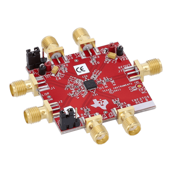
This user's guide provides instructions for evaluating the TRF37T05 modulator with a TRF37T05EVM
evaluation module. The TRF37T05 is a quadrature modulator for up-converting the in-phase (I) and
quadrature-phase (Q) signals to RF signals in the transmit chain, typically used between the digital-to-
analog converter and the RF power amplifier.
1
1.1
1.2
2
2.1
2.2
2.3
3
3.1
3.2
1
2
3
1
Default Jumper Connections
SLWU084 - June 2013
Submit Documentation Feedback
TRF37T05EVM Evaluation Module
..................................................................................................................
............................................................................................
.......................................................................................
......................................................................................
................................................................................................
.....................................................................................................
...........................................................................................................
.......................................................................................................
.................................................................................
..............................................................................................
.......................................................................................
.................................................................................................
........................................................................................
..............................................................................................
Copyright © 2013, Texas Instruments Incorporated
Contents
List of Figures
List of Tables
User's Guide
SLWU084 - June 2013
TRF37T05EVM Evaluation Module
2
2
2
3
3
3
3
4
4
5
2
3
5
2
1
Advertisement
Table of Contents

Related Manuals for Texas Instruments TRF37T05EVM


Summary of Contents for Texas Instruments TRF37T05EVM
-
Page 1: Table Of Contents
SLWU084 – June 2013 TRF37T05EVM Evaluation Module This user's guide provides instructions for evaluating the TRF37T05 modulator with a TRF37T05EVM evaluation module. The TRF37T05 is a quadrature modulator for up-converting the in-phase (I) and quadrature-phase (Q) signals to RF signals in the transmit chain, typically used between the digital-to- analog converter and the RF power amplifier. -
Page 2: Introduction
(EVM). Table 1. Default Jumper Connections Jumper Description Default Notes Power Down Pins 2-3 Powered On Gain Control Pins 2-3 Low Gain Mode TRF37T05EVM Evaluation Module SLWU084 – June 2013 Submit Documentation Feedback Copyright © 2013, Texas Instruments Incorporated... -
Page 3: Trf37T05 Evm Test Configuration
Measure the insertion loss of the RF output cable, and use this value to compensate for the measured output power. • Measure the insertion loss of the LO input cable, and use this value to compensate for the desired LO power. SLWU084 – June 2013 TRF37T05EVM Evaluation Module Submit Documentation Feedback Copyright © 2013, Texas Instruments Incorporated... -
Page 4: Evm Test Procedure
= 1005.5 MHz. The RF power must be 3.5 dBm ± 1 dBm after the RF cable loss is compensated. TRF37T05EVM Evaluation Module SLWU084 – June 2013 Submit Documentation Feedback Copyright © 2013, Texas Instruments Incorporated... -
Page 5: Two-Tone Oip3 Test
RF attenuation setting. 0_low 0_high IM3_low IM3_low +(f -f ) LO 2 LO 1 LO 1 LO 2 Figure 3. Two-Tone OIP3 Output Spectrum SLWU084 – June 2013 TRF37T05EVM Evaluation Module Submit Documentation Feedback Copyright © 2013, Texas Instruments Incorporated... - Page 6 Any exceptions to this are strictly prohibited and unauthorized by Texas Instruments unless user has obtained appropriate experimental/development licenses from local regulatory authorities, which is responsibility of user including its acceptable authorization.
- Page 7 FCC Interference Statement for Class B EVM devices This equipment has been tested and found to comply with the limits for a Class B digital device, pursuant to part 15 of the FCC Rules. These limits are designed to provide reasonable protection against harmful interference in a residential installation. This equipment generates, uses and can radiate radio frequency energy and, if not installed and used in accordance with the instructions, may cause harmful interference to radio communications.
- Page 8 Also, please do not transfer this product, unless you give the same notice above to the transferee. Please note that if you could not follow the instructions above, you will be subject to penalties of Radio Law of Japan. Texas Instruments Japan Limited (address) 24-1, Nishi-Shinjuku 6 chome, Shinjuku-ku, Tokyo, Japan http://www.tij.co.jp...
- Page 9 FDA Class III or similar classification, then you must specifically notify TI of such intent and enter into a separate Assurance and Indemnity Agreement. Mailing Address: Texas Instruments, Post Office Box 655303, Dallas, Texas 75265 Copyright © 2013, Texas Instruments Incorporated...
- Page 10 IMPORTANT NOTICE Texas Instruments Incorporated and its subsidiaries (TI) reserve the right to make corrections, enhancements, improvements and other changes to its semiconductor products and services per JESD46, latest issue, and to discontinue any product or service per JESD48, latest issue.
Need help?
Do you have a question about the TRF37T05EVM and is the answer not in the manual?
Questions and answers