
Subscribe to Our Youtube Channel
Related Manuals for Texas Instruments TRF370 Series


Summary of Contents for Texas Instruments TRF370 Series
- Page 1 TRF370x Quadrature Modulator Evaluation Module User's Guide Literature Number: SLWU062 March 2010...
- Page 2 SLWU062 – March 2010 Submit Documentation Feedback Copyright © 2010, Texas Instruments Incorporated...
- Page 3 TRF370x EVM Operating Procedure ......................Physical Description ......................PCB Layout ........................ Parts List ......................Circuit Description ......................Circuit Function ........................Circuit Board ......................... Schematic SLWU062 – March 2010 Table of Contents Submit Documentation Feedback Copyright © 2010, Texas Instruments Incorporated...
-
Page 4: Table Of Contents
Drill Pattern ..................... Silkscreen Top Layer ....................TRF370x EVM Schematic List of Tables ..................Bill of Materials for TRF370x EVM ....................Power Supply Connection List of Figures SLWU062 – March 2010 Submit Documentation Feedback Copyright © 2010, Texas Instruments Incorporated... - Page 5 Header TP4 supplies 5 V to the LO circuitry, and TP2 supplies 5 V to the modulator circuitry. CAUTION Voltage Limits Exceeding 5.6 V may damage the TRF370x. SLWU062 – March 2010 TRF370x Quadrature Modulator Evaluation Module Submit Documentation Feedback Copyright © 2010, Texas Instruments Incorporated...
-
Page 6: Unadjusted Sideband Suppression
This suppression is the one specified in the TRF370x data sheet. See Figure TRF370x Quadrature Modulator Evaluation Module SLWU062 – March 2010 Submit Documentation Feedback Copyright © 2010, Texas Instruments Incorporated... -
Page 7: Optimized Sideband Suppression
DAC is used, then the user must provide this level of adjustment by controlling the regular digital inputs to the DAC. See Figure SLWU062 – March 2010 TRF370x Quadrature Modulator Evaluation Module Submit Documentation Feedback Copyright © 2010, Texas Instruments Incorporated... - Page 8 0.85 V, depending on device) → I/Q → I/Q output control → I/Q output atten (adjust to get desired transmit power to either 0 or –5 dBm). Figure TRF370x Quadrature Modulator Evaluation Module SLWU062 – March 2010 Submit Documentation Feedback Copyright © 2010, Texas Instruments Incorporated...
-
Page 9: Gsm Edge Evm At 1800 Mhz
TRF370333 with options for selecting the desired amount of attenuation between the two. Additional interfacing networks for each modulator can be found in their respective data sheets or by using the DAC interface calculator (SLWC083). SLWU062 – March 2010 TRF370x Quadrature Modulator Evaluation Module Submit Documentation Feedback Copyright © 2010, Texas Instruments Incorporated... -
Page 10: V Interface Network For 19.2 Ma Full Scale
3 dB 4 dB 5 dB Pullup Pulldown Series 37.4 45.3 Shunt Figure 5. 3.3-V Interface Network for 19.2 mA Full Scale TRF370x Quadrature Modulator Evaluation Module SLWU062 – March 2010 Submit Documentation Feedback Copyright © 2010, Texas Instruments Incorporated... -
Page 11: Top Layer
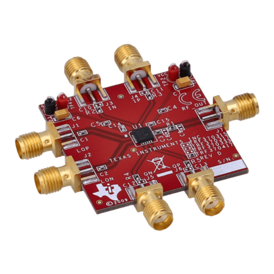
The EVM is constructed on a four-layer, 38,1-mm × 38,1-mm × 1,579-mm thick PCB using FR-4 material. Figure 6 through Figure 12 show the individual layers. K001 Figure 6. Top Layer 1 SLWU062 – March 2010 TRF370x Quadrature Modulator Evaluation Module Submit Documentation Feedback Copyright © 2010, Texas Instruments Incorporated... -
Page 12: Top Layer
Physical Description www.ti.com K002 Figure 7. Top Layer 2 K003 Figure 8. Ground Plane 1 TRF370x Quadrature Modulator Evaluation Module SLWU062 – March 2010 Submit Documentation Feedback Copyright © 2010, Texas Instruments Incorporated... -
Page 13: Ground Plane
Physical Description www.ti.com K004 Figure 9. Ground Plane 2 K005 Figure 10. Bottom Layer 1 SLWU062 – March 2010 TRF370x Quadrature Modulator Evaluation Module Submit Documentation Feedback Copyright © 2010, Texas Instruments Incorporated... -
Page 14: Bottom Layer
Physical Description www.ti.com K006 Figure 11. Bottom Layer 2 TRF370x Quadrature Modulator Evaluation Module SLWU062 – March 2010 Submit Documentation Feedback Copyright © 2010, Texas Instruments Incorporated... -
Page 15: Drill Pattern
Physical Description www.ti.com D001 Figure 12. Drill Pattern SLWU062 – March 2010 TRF370x Quadrature Modulator Evaluation Module Submit Documentation Feedback Copyright © 2010, Texas Instruments Incorporated... -
Page 16: Bill Of Materials For Trf370X Evm
Two SMA connectors are provided for LO input: J1 = LOP and J2 = LON. Terminate whichever LO port is not being used through 50 Ω to ground. • One SMA connector is for RF_OUT: J7. TRF370x Quadrature Modulator Evaluation Module SLWU062 – March 2010 Submit Documentation Feedback Copyright © 2010, Texas Instruments Incorporated... -
Page 17: Silkscreen Top Layer
This chapter shows the circuit board test points. +5 V +5 V BBIN BBIP RF_OUT 50 W BBQP BBQN K007 Figure 13. Silkscreen Top Layer SLWU062 – March 2010 TRF370x Quadrature Modulator Evaluation Module Submit Documentation Feedback Copyright © 2010, Texas Instruments Incorporated... -
Page 18: Trf370X Evm Schematic
GND6 100pF SMA_END TRF370333 TRF370317 TRF370315 SMA_END SMA_END TRF370417 .1uF .1uF S0214-03 DNI = Do not install. Figure 14. TRF370x EVM Schematic TRF370x Quadrature Modulator Evaluation Module SLWU062 – March 2010 Submit Documentation Feedback Copyright © 2010, Texas Instruments Incorporated... - Page 19 EVALUATION BOARD/KIT IMPORTANT NOTICE Texas Instruments (TI) provides the enclosed product(s) under the following conditions: This evaluation board/kit is intended for use for ENGINEERING DEVELOPMENT, DEMONSTRATION, OR EVALUATION PURPOSES ONLY and is not considered by TI to be a finished end-product fit for general consumer use. Persons handling the product(s) must have electronics training and observe good engineering practice standards.
- Page 20 IMPORTANT NOTICE Texas Instruments Incorporated and its subsidiaries (TI) reserve the right to make corrections, modifications, enhancements, improvements, and other changes to its products and services at any time and to discontinue any product or service without notice. Customers should obtain the latest relevant information before placing orders and should verify that such information is current and complete.
Need help?
Do you have a question about the TRF370 Series and is the answer not in the manual?
Questions and answers