
Subscribe to Our Youtube Channel
Related Manuals for Texas Instruments TRF3703


Summary of Contents for Texas Instruments TRF3703
- Page 1 TRF3703 Quadrature Modulator Evaluation Module User's Guide December 2006 Wireless Infrastructure Radio SLWU042A...
- Page 2 SLWU042A – October 2006 – Revised December 2006 Submit Documentation Feedback...
-
Page 3: Table Of Contents
Contents ........................Overview ......................Purpose ................... EVM Circuit Overview .................... Power Requirements ................TRF3703 EVM Operating Procedure ....................Physical Description ...................... PCB Layout ......................Parts List ..................... Circuit Description ....................Circuit Function ......................Circuit Board ........................ Schematic SLWU042A – October 2006 – Revised December 2006... - Page 4 Layer 4—Bottom Layer–NH ........................Drill Pattern ...................... Silkscreen Top Layer ....................TRF3703 EVM Schematic List of Tables ..................Bill of Materials for TRF3703 EVM ......................Power Supply J1 List of Figures SLWU042A – October 2006 – Revised December 2006 Submit Documentation Feedback...
-
Page 5: Overview
The TRF3703 operates between 400 MHz and 4 GHz. The quadrature modulator is used for upconversion of signals from the transmit chain DAC to the RF power amplifier device. Evaluating modulator complex performance involves careful bias-voltage setup, an LO signal, and two differential (I/Q) signals at the input of the modulator. -
Page 6: Trf3703 Evm Operating Procedure
(5-V) supply and set the current limit set to 235 mA. b. Connect the 5-V supply to headers W1 and W2. c. Verify that the current drawn is approximately ≤ 205 mA for the TRF3703-15 and ≤ 235 mA for the TRF3703-33. -
Page 7: Un-Optimized Sideband Suppression
Optimized Sideband Supression There are two ways to change the sideband suppression of the TRF3703. One is the amplitude between the four inputs, and the second is the phase of the four inputs. The ideal condition is when all four inputs (I, I, Q, and Q) have exactly the same amplitude and the phase relationship is: I = 0°, I = 180°, Q = 90°,... -
Page 8: Optimized Sideband Suppression
Carrier feedthrough is the amount of the LO that leaks onto the output spectrum of the modulator. Ideally for the TRF3703, inputs (I, I, Q, and Q) must be at approximately 3.3 V for TRF3703-33 and 1.5 V for TRF3703-15. The DAC dc settings are also useful to correct the dc mismatch between I and I and between Q and Q to correct for the LO feedthrough. -
Page 9: Gsm Edge Evm At 1800 Mhz
1.4.2 Interface to TI's DAC Both the TRF3703-33 and the TRF3703-15 work well with TI's DACs. The TRF3703-33 is well suited to work with TI's DAC568X family, and the TRF3703-15 is well suited to work with TI's DAC56X2 series. Each DAC series is optimized to work at certain common-mode voltage. The DAC568X has a common-mode of 3.3 V, while the DAC56X2 has a 0.7-V common-mode voltage. -
Page 10: V Interface Network For 19.2 Ma Full Scale
2 dB 3 dB 4 dB 5 dB Pullup Pulldown Series 37.4 45.3 Shunt Figure 5. 3.3-V Interface Network for 19.2 mA Full Scale TRF3703 Quadrature Modulator Evaluation Module SLWU042A – October 2006 – Revised December 2006 Submit Documentation Feedback... -
Page 11: Physical Description
The EVM is constructed on a four-layer, 38,1-mm × 38,1-mm × 1,579-mm thick PCB using FR-4 material. Figure 6 through Figure 12 show the individual layers. K001 Figure 6. Top Layer SLWU042A – October 2006 – Revised December 2006 TRF3703 Quadrature Modulator Evaluation Module Submit Documentation Feedback... -
Page 12: Top Layer-Nh
Physical Description K002 Figure 7. Top Layer–NH TRF3703 Quadrature Modulator Evaluation Module SLWU042A – October 2006 – Revised December 2006 Submit Documentation Feedback... -
Page 13: Ground Plane L2
Physical Description K003 Figure 8. Ground Plane L2 SLWU042A – October 2006 – Revised December 2006 TRF3703 Quadrature Modulator Evaluation Module Submit Documentation Feedback... -
Page 14: Ground Plane L3
Physical Description K004 Figure 9. Ground Plane L3 TRF3703 Quadrature Modulator Evaluation Module SLWU042A – October 2006 – Revised December 2006 Submit Documentation Feedback... -
Page 15: Layer 4-Bottom Layer
Physical Description K005 Figure 10. Layer 4—Bottom Layer SLWU042A – October 2006 – Revised December 2006 TRF3703 Quadrature Modulator Evaluation Module Submit Documentation Feedback... -
Page 16: Layer 4-Bottom Layer-Nh
Physical Description K006 Figure 11. Layer 4—Bottom Layer–NH TRF3703 Quadrature Modulator Evaluation Module SLWU042A – October 2006 – Revised December 2006 Submit Documentation Feedback... -
Page 17: Drill Pattern
Physical Description 10 mil 0.254 mm 12 mil 0.3048 mm 13 mil 0.3302 mm 37 mil 0.9398 mm Total D001 Figure 12. Drill Pattern SLWU042A – October 2006 – Revised December 2006 TRF3703 Quadrature Modulator Evaluation Module Submit Documentation Feedback... -
Page 18: Parts List
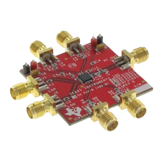
• Four SMA connectors are provided on the EVM for inputting differential I/Q signals directly to the input pins of the TRF3703. Connectors J3, J4, J5, and J6 are used to connect the signal source I/Q signals directly to the TRF3703. -
Page 19: Circuit Board
This chapter shows the circuit board test points. +5 V +5 V BBIN BBIP RF_OUT 50 W BBQP BBQN K001 Figure 13. Silkscreen Top Layer SLWU042A – October 2006 – Revised December 2006 TRF3703 Quadrature Modulator Evaluation Module Submit Documentation Feedback... -
Page 20: Schematic
TRF3703 0.1 F 0.1 F (Note 1) (Note 1) SMA_END 100 pF SMA_END SMA_END S0214-01 (1) Do not install. Figure 14. TRF3703 EVM Schematic TRF3703 Quadrature Modulator Evaluation Module SLWU042A – October 2006 – Revised December 2006 Submit Documentation Feedback... - Page 21 TI product or service and is an unfair and deceptive business practice. TI is not responsible or liable for any such statements. Following are URLs where you can obtain information on other Texas Instruments products and application solutions:...
Need help?
Do you have a question about the TRF3703 and is the answer not in the manual?
Questions and answers