Table of Contents
Advertisement
Quick Links
Video-inserter
RL4-SY3-R5
Compatible with Ford vehicles with
Sync2.5 (Sync3 light/R5) version
with 6.5, 7 or 8inch tablet monitor
Sync Connected Radio version
with 4inch monitor
Sync3 full version with APIM and with
7inch or 8inch monitor
Video-inserter for front- and rear-view camera
and two additional video sources
Product features
Video-inserter for factory-infotainment systems
1 CVBS Input for rear-view camera
1 CVBS Input for front camera
2 CVBS video-inputs for after-market devices (e.g. USB-Player, DVB-T2 tuner)
Automatic switching to rear-view camera input on engagement of the reverse gear
Automatic front camera switching after reverse gear for 10 seconds
Activatable parking guide lines for rear-view camera (not available for all vehicles)
Activatable PDC (not available for all vehicles)
Video-in-motion (ONLY for connected video-sources)
Video-inputs NTSC compatible
Version 13.02.2023
HW: CAM(100)/(V21+V41.3)
ab Serien Nr: NZ20NOV694
RL4-SY3-R5
Advertisement
Table of Contents

Related Manuals for NavLinkz RL4-SY3-R5


Summary of Contents for NavLinkz RL4-SY3-R5
- Page 1 Video-inserter RL4-SY3-R5 Compatible with Ford vehicles with Sync2.5 (Sync3 light/R5) version with 6.5, 7 or 8inch tablet monitor Sync Connected Radio version with 4inch monitor Sync3 full version with APIM and with 7inch or 8inch monitor Video-inserter for front- and rear-view camera...
-
Page 2: Table Of Contents
Case 2: Interface does not receive the reverse gear signal 3.4. Connection video-interface and keypad 3.5. Picture settings 4. Interface operation 4.1. By infotainment button 4.2. By keypad 5. Specifications 6. FAQ – Trouble Shooting-Interface functions 7. Technical support Version 13.02.2023 HW: CAM(100)/(V21+V41.3) ab Serien Nr: NZ20NOV694 RL4-SY3-R5... -
Page 3: Prior To Installation
The place of installation has to be free of moisture and away from heat sources. 1.1. Delivery contents Take down the serial number of the interface and store this manual for support purposes: ____________________ Version 13.02.2023 HW: CAM(100)/(V21+V41.3) ab Serien Nr: NZ20NOV694 RL4-SY3-R5... -
Page 4: Checking The Compatibility Of Vehicle And Accessories
A manually front camera switching is possible by external keypad. Guidelines and PDC Displayed guidelines and PDC are not available in all vehicles. Video input signal NTSC video sources compatible only. Version 13.02.2023 HW: CAM(100)/(V21+V41.3) ab Serien Nr: NZ20NOV694 RL4-SY3-R5... -
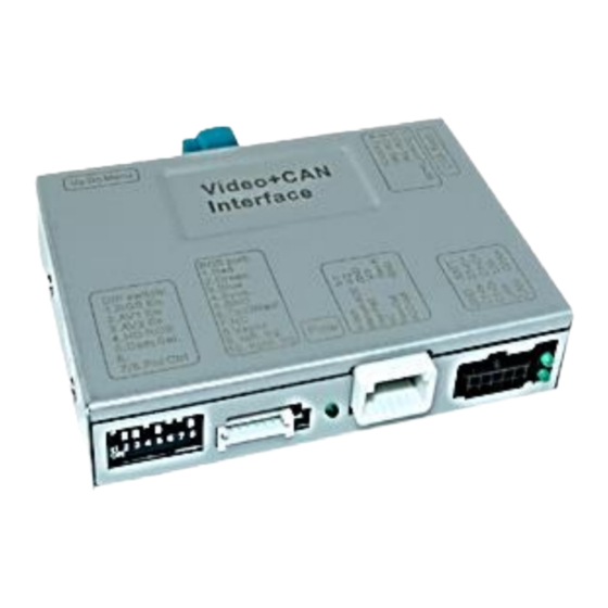
Page 5: Connectors - Video Interface
Further it reads the vehicle’s digital signals out of the vehicle’s CAN-bus and converts them for the video interface. Version 13.02.2023 HW: CAM(100)/(V21+V41.3) ab Serien Nr: NZ20NOV694 RL4-SY3-R5... -
Page 6: Dip Switch Settings
*The front camera will automatically be switched for 10 seconds after disengaging the reverse gear. After each Dip-switch-change a power-reset of the Video Interface has to be performed! See the following chapters for detailed information. Version 13.02.2023 HW: CAM(100)/(V21+V41.3) ab Serien Nr: NZ20NOV694 RL4-SY3-R5... -
Page 7: Activating The Front Camera Input (Dip 1)
If set to OFF, 6.5-, 7- and 8inch monitors are selected on the interface. Note: Dip8 is out of function and has to be set to OFF. After each Dip-switch-change a power-reset of the Video Interface has to be performed! Version 13.02.2023 HW: CAM(100)/(V21+V41.3) ab Serien Nr: NZ20NOV694 RL4-SY3-R5... -
Page 8: Dip - Red
(head unit), a DIN housing. In most vehicles, this is located behind/below the monitor in the centre console. There is no APIM module with these Sync versions. Version 13.02.2023 HW: CAM(100)/(V21+V41.3) ab Serien Nr: NZ20NOV694 RL4-SY3-R5... -
Page 9: Connection Schema
2.2. Connection schema Version 13.02.2023 HW: CAM(100)/(V21+V41.3) ab Serien Nr: NZ20NOV694 RL4-SY3-R5... -
Page 10: Connection - Picture Signal Cable
Note: No liability for vehicle wire colours and pin definition! Changes by the vehicle manufacturer are possible. The given information has to be verified by the installer. Version 13.02.2023 HW: CAM(100)/(V21+V41.3) ab Serien Nr: NZ20NOV694 RL4-SY3-R5... -
Page 11: Connection - Pnp Power / Can Cable
32pin connector of the enclosed PNP Power/CAN cable. Connect the enclosed PNP Power / CAN cable’s opposite female 32pin connector to the previously become free male 32pin connector of the head-unit. Version 13.02.2023 HW: CAM(100)/(V21+V41.3) ab Serien Nr: NZ20NOV694 RL4-SY3-R5... -
Page 12: Special Case: Sync3 Full Version
Installation location is behind the monitor and on the APIM module - the APIM module is located behind the centre console or behind the glove box. Note: The radio module is a separate DIN-sized module and is NOT required for installation! Version 13.02.2023 HW: CAM(100)/(V21+V41.3) ab Serien Nr: NZ20NOV694 RL4-SY3-R5... - Page 13 Connect the single brown cable to the vehicle’s Ground. Note: No liability for vehicle wire colours and pin definition! Changes by the vehicle manufacturer are possible. The given information has to be verified by the installer. Version 13.02.2023 HW: CAM(100)/(V21+V41.3) ab Serien Nr: NZ20NOV694 RL4-SY3-R5...
- Page 14 Connect the single brown cable to the vehicle’s Ground. Note: No liability for vehicle wire colours and pin definition! Changes by the vehicle manufacturer are possible. The given information has to be verified by the installer. Version 13.02.2023 HW: CAM(100)/(V21+V41.3) ab Serien Nr: NZ20NOV694 RL4-SY3-R5...
-
Page 15: Installation With Analogue Connection (Without Can-Bus)
Connect the female 12pin connector of the 12pin interface cable to the male 12pin connector of the video interface. Connect the 12pin interface cable’s purple coloured wire Manual ACC to+12V ACC S-contact terminal 86s +12V (e.g. glove compartment illumination). Version 13.02.2023 HW: CAM(100)/(V21+V41.3) ab Serien Nr: NZ20NOV694 RL4-SY3-R5... -
Page 16: Power Supply Output
+12V (max. 3A) when reverse gear is engaged incl. 10 seconds delay after reverse gear is disengaged and +12V by manual switching to front camera by keypad (short press) Dip 1 OFF +12V (max. 3A) ACC Version 13.02.2023 HW: CAM(100)/(V21+V41.3) ab Serien Nr: NZ20NOV694 RL4-SY3-R5... -
Page 17: Connection - Video Sources
Connect the front camera’s video RCA connector to the 12pin interface cable’s female RCA connector „Front V3“. Connect the video RCA of the AV source 1 and 2 to the 12pin interface cable’s female RCA connector “Left (V1)” ”Right (V2)”. Version 13.02.2023 HW: CAM(100)/(V21+V41.3) ab Serien Nr: NZ20NOV694 RL4-SY3-R5... -
Page 18: Audio Insertion
(short press) from any image mode. The power supply output gives +12V then, as well (if Dip 1 is set to ON and the front camera input is selected). Attention: A long press of the external keypad push button will switch the interface to the next source. Version 13.02.2023 HW: CAM(100)/(V21+V41.3) ab Serien Nr: NZ20NOV694 RL4-SY3-R5... -
Page 19: After-Market Rear-View Camera
The 12 V power supply for the rear-view camera (max 3A) has to be taken from the 12pin interface cabl’s green wire “Reverse-OUT” to avoid an unnecessary, permanent power supply to the camera electronic. Both green cables “Reverse IN” “Reverse OUT” have to remain connected. Version 13.02.2023 HW: CAM(100)/(V21+V41.3) ab Serien Nr: NZ20NOV694 RL4-SY3-R5... -
Page 20: Case 2: Interface Does Not Receive The Reverse Gear Signal
Connect the output connector (87) of the relay to the rear-view camera’s power- cable, like you did it to the green “Reverse-IN” cable before. Connect permanent power / 12V to the relay’s input connector (30). Version 13.02.2023 HW: CAM(100)/(V21+V41.3) ab Serien Nr: NZ20NOV694 RL4-SY3-R5... -
Page 21: Connection Video-Interface And Keypad
Connect the keypad’s female 4pin connector to the 12pin interface cable’s male 4pin connector. Note: Even if the switching through several video sources by the keypad mightn’t be required, the keypad’s invisible connection and availability is strongly recommended. Version 13.02.2023 HW: CAM(100)/(V21+V41.3) ab Serien Nr: NZ20NOV694 RL4-SY3-R5... -
Page 22: Picture Settings
Note: The OSD menu is only shown when a working video source is connected to the selected video-input of the interface. The following settings are available Contrast Brightness Saturation Position H (horizontal picture position) Position V (vertical picture position) Version 13.02.2023 HW: CAM(100)/(V21+V41.3) ab Serien Nr: NZ20NOV694 RL4-SY3-R5... -
Page 23: Interface Operation
Short press of keypad (only if DIP 1 is set to ON) By short pressing the external keypad, the video interfaces witches from the factory video to the front camera input and back to factory video. Version 13.02.2023 HW: CAM(100)/(V21+V41.3) ab Serien Nr: NZ20NOV694 RL4-SY3-R5... -
Page 24: Specifications
0.7V - 1V Video input formats NTSC RGB-video amplitude 0.7V with 75 Ohm impedance Temperature range -40°C to +85°C Dimensions video-box 118 x 25 x 104 mm (W x H x D) Version 13.02.2023 HW: CAM(100)/(V21+V41.3) ab Serien Nr: NZ20NOV694 RL4-SY3-R5... -
Page 25: Faq - Trouble Shooting-Interface Functions
Test camera under natural light outside the garage. flickers. directly into the camera. Camera input picture is Protection sticker not Remove protection sticker from lens. bluish. removed from camera lens. Version 13.02.2023 HW: CAM(100)/(V21+V41.3) ab Serien Nr: NZ20NOV694 RL4-SY3-R5... -
Page 26: Technical Support
6pin to 8pin cable and isolate both ends. Technical Support Please note that direct technical support is only available for products purchased directly from NavLinkz GmbH. For products bought from other sources, contact your vendor for technical support. NavLinkz GmbH...
Need help?
Do you have a question about the RL4-SY3-R5 and is the answer not in the manual?
Questions and answers