
Related Manuals for FIC PA-2006


Summary of Contents for FIC PA-2006
- Page 1 PA-2006 MAINBOARD MANUAL DOC No. : 15579 Rev. : A2 Date : 4, 1997 Part No. : 25-10580-05...
-
Page 2: Table Of Contents
Table of Contents Chapter 1 Overview Main Features ..................2 This User Manual .................. 4 Something Interesting................5 The BIOS Setup Utility ..............5 IRQ Functionality................6 DMA Channels of ISA Cards ............7 Enhanced IDE ................7 Serial Infrared (SIR) Connections..........8 Highly Convenient Integrated I/O Connectors ........ - Page 3 PA-2006 Mainboard Manual CPU to Bus Frequency Ratio Selection: FREQ1, FREQ2..............27 Intel Pentium CPUs ............... 28 Frequency................. 28 Voltage................29 AMD-K5/K6 CPUs..............30 Frequency................. 30 Voltage................31 Cyrix 6x86 CPUs..............32 Frequency................. 32 Voltage................33 IBM 6x86 CPUs ..............34 Frequency.................
- Page 4 Installation Procedures Chipset Features Setup................53 Power Management Setup ..............58 PCI Configuration Setup................. 61 PnP Configuration Setup ................ 63 Load BIOS Defaults ................64 Load Setup Defaults................64 Supervisor/User Password..............64 IDE HDD Auto Detection............... 65 Save and Exit Setup ................66 Exit without Saving................
- Page 5 PA-2006 Mainboard Manual This Page Intentionally Left Blank...
-
Page 6: Chapter 1 Overview
SIR support further enhance system I/O connectivity. This chapter gives you a brief overview of the PA-2006 mainboard. In addition to basic information on the board's main components and features, it also provides advice on how to upgrade and expand it. For updated BIOS, drivers, or product release information, please visit FIC's home page at: http://www.fic.com.tw. -
Page 7: Main Features
PA-2006 Mainboard Manual Main Features The PA-2006 mainboard comes with the following high-performance features: n Easy Installation Award BIOS with support for Plug and Play, auto detection of Hard Drive and IDE features, MS Windows 95, and Windows NT compatible. - Page 8 Overview n USB Support Onboard support for two Universal Serial Bus connectors via a plug-in connector. n Enhanced PCI Bus Master IDE Controller Integrated Enhanced PCI local bus IDE controller with two connectors supports up to four IDE devices such as Hard Disk, CD-ROM or Tape Backup drives via two channels for high speed data throughput.
-
Page 9: This User Manual
PA-2006 Mainboard Manual This User Manual This manual is designed to guide you and facilitate your use of the PA-2006 mainboard. It contains a description of the design and features of the mainboard, and also includes useful information for changing the configuration of the board and the system it is installed in. -
Page 10: Something Interesting
Overview Something Interesting This section provides useful information that you will need to know should you decide to modify or upgrade the configuration of the mainboard and the system it is installed in. If you do not have the confidence to upgrade the mainboard yourself, we advise that you consult a qualified service technician for assistance. -
Page 11: Irq Functionality
PA-2006 Mainboard Manual IRQ Functionality As you read through this manual, you will see the term IRQ on a number of occasions. It is important for you to know what this term means, particularly if you intend to upgrade your system. -
Page 12: Dma Channels Of Isa Cards
Overview DMA Channels of ISA Cards Some Legacy and PnP ISA add-on cards may also need to use a Direct Memory Access (DMA) channel. DMA assignments for this mainboard are handled in the same way as the IRQ assignment process outlined above. For more information, please refer to Chapter 3 of this manual. -
Page 13: Serial Infrared (Sir) Connections
PA-2006 Mainboard Manual Serial Infrared (SIR) Connections This mainboard features support for highly-sophisticated SIR technology, which allows bi-directional and cordless data transactions with other IrDA compliant computers and peripheral devices using infrared as a medium. This transmission is carried out in either Full Duplex Mode or Half Duplex Mode. -
Page 14: Highly Convenient Integrated I/O Connectors
Overview Highly Convenient Integrated I/O Connectors This mainboard features has an integrated rear I/O panel that incorporates a full set of I/O ports to allow simple and convenient connections to a complete selection of external peripheral devices. In addition to two 16550A UART compatible serial ports and one EPP/ECP capable parallel port, the panel features two USB connectors that provide high speed connection to the next generation of USB devices. - Page 15 PA-2006 Mainboard Manual This Page Intentionally Left Blank...
-
Page 16: Chapter 2 Installation Procedures
Chapter 2 Installation Procedures The PA-2006 has several user-adjustable jumpers on the board that allow you to configure your system to suit your requirements. This chapter contains information on the various jumper settings on your mainboard. To set up your computer, you should follow these installation steps:... -
Page 17: Mainboard Layout
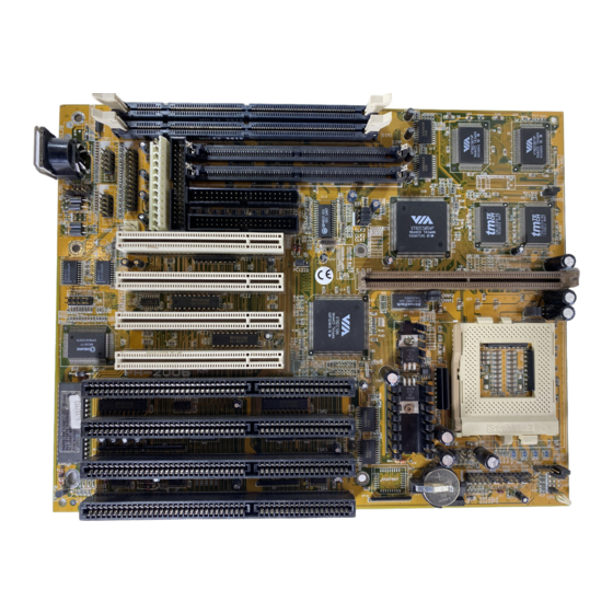
PA-2006 Mainboard Manual Mainboard Layout... -
Page 18: Set System Jumpers
Installation Procedures 1). Set System Jumpers Jumpers Jumpers are used to select the operation modes for your system. Some jumpers on the board have three metal pins with each pin representing a different function. To set a jumper, a black cap containing metal contacts is placed over the jumper pin/s according to the required configuration. -
Page 19: Clear Password: Cpw
PA-2006 Mainboard Manual Clear Password: CPW This jumper allows you to set the password configuration to Enabled or Disabled. You may need to enable this jumper if you forget your password. PCI2 ID: PCI2ID This setting is provided to allow you to install more than one PCI add-on card released before the launch of the PCI Encoding Standard in 1993. -
Page 20: Cpu To Sram Data Transacting Mode Selection: Sram3
Installation Procedures CPU to SRAM Data Transacting Mode Selection: SRAM3 This jumper allows you to select the CPU to SRAM data read/write mode. Also, you need to configure the Chipset feature, Linear Bust Mode, in Page 54. Please refer to it. -
Page 21: Install Dram Modules
The PA-2006’ s RAM is comprised of two industry standard 72-pin Single In-line Memory Modules (SIMMs) and two 168-pin Dual In-line Memory Modules (DIMMs). The SIMM sockets are able to support 8 to 256MB FPM (Fast Page Mode) and high-speed EDO (Extended Data Out) DRAM. -
Page 22: Ram Module Configuration
Installation Procedures RAM Modules Configuration (Unit : MB) TOTAL SIMM2 SIMM1 DIM1 DIM2 MEMORY BANK 2 BANK 2 BANK 0 BANK 1 (continued on next page) - Page 23 PA-2006 Mainboard Manual (continued) TOTAL SIMM2 SIMM1 DIM1 DIM2 MEMORY BANK 2 BANK 2 BANK 0 BANK 1 (continued on next page)
- Page 24 Installation Procedures (continued) TOTAL SIMM2 SIMM1 DIM1 DIM2 MEMORY BANK 2 BANK 2 BANK 0 BANK 1 128* 128* 128* 128* 128* 128* 128* 128* 128* 128* 128* 128* 128* 128* 128* 128* NOTE : 1. * A RAM module of this size was not available for testing when this manual was printed.
-
Page 25: Install Simms
PA-2006 Mainboard Manual Install SIMMs Complete the following procedures to install SIMMs: CAUTION : Always turn the system power off before installing or removing any device; and see “ Handling Precautions” at the start of this manual. 1. Locate the SIMM slots on the mainboard. (See figure below.) NOTE : SIMMs in each bank must be of the same type;... -
Page 26: Install Dimms
Installation Procedures Install DIMMs Complete the following procedures to install DIMMs: 1. Locate the DIMM slots on the mainboard. (See figure below.) 2. Carefully insert the DIMM straight down onto the DIMM slot with both hands until the clips on the ends of the slot close up to hold the DIMM in place. -
Page 27: Cache Memory
PA-2006 Mainboard Manual Cache Memory The PA-2006 comes with onboard 256KB/512KB synchronous 3V Pipeline Burst SRAM, and one optional 256KB/512KB cache SRAM module (FIC’ s PB512K-3.0 is recommended*) that can be installed on the cache SRAM module slot. NOTE : 1. -
Page 28: Onboard Cache Sram (256Kb/512Kb)
Installation Procedures Onboard Cache SRAM (256KB/512KB) NOTE : Use the correct chips for the amount of cache memory you want to add. Install both the correct Cache and Tag SRAM. -
Page 29: Onboard Cache Sram And Sdram Module Mixture
PA-2006 Mainboard Manual Onboard Cache SRAM and SRAM Module Mixture (512KB/1MB) NOTE : Use the correct chips for the amount of cache memory you want to add. Install both the correct Cache and Tag SRAM. -
Page 30: Sram Module (256Kb/512Kb)
Installation Procedures SRAM Module (256KB/512KB) NOTE : Use the correct chips for the amount of cache memory you want to add. Install both the correct Cache and Tag SRAM. -
Page 31: Install The Cpus
PA-2006 Mainboard Manual 3). Install the CPU The CPU module resides in the Zero Insertion Force (ZIF) socket on the mainboard. CAUTION : Always turn the system power off before installing or removing any device. Always observe static electricity precautions. -
Page 32: System Clock Selection:
Installation Procedures CPU External Clock (Bus) Frequency: CLK1, CLK2, and CLK3 The table below shows the jumper settings for the different CPU speed configurations. CPU to Bus Frequency Ratio: FREQ1 and FREQ2 These two jumpers are used in combination to decide the ratio of the internal frequency of the CPU to the bus clock. -
Page 33: Intel Pentium Cpus
PA-2006 Mainboard Manual Intel Pentium CPUs Frequency... -
Page 34: Voltage
Installation Procedures Voltage... -
Page 35: Amd-K5/K6 Cpus
PA-2006 Mainboard Manual AMD-K5/K6 CPUs Frequency... -
Page 36: Voltage
Installation Procedures Voltage... -
Page 37: Cyrix 6X86 Cpus
PA-2006 Mainboard Manual Cyrix 6x86 CPUs Frequency NOTE : * This CPU had not been tested when this manual was printed. -
Page 38: Voltage
Installation Procedures Voltage NOTE : * This CPU had not been tested when this manual was printed. -
Page 39: Ibm 6X86 Cpus
PA-2006 Mainboard Manual IBM 6x86 CPUs Frequency NOTE : * This CPU had not been tested when this manual was printed. -
Page 40: Voltage
Installation Procedures Voltage NOTE : * This CPU had not been tested when this manual was printed. -
Page 41: Installation Of Cyrix (Or Ibm) 6X86 Cpu Fan
PA-2006 Mainboard Manual Installation of Cyrix (or IBM) 6x86 CPU Fan CAUTION : When you install a Cyrix (or IBM) 6x86 CPU fan, please pay attention to the direction of the air flow. Make sure the air flow is the direction of the regulator;... -
Page 42: Install Expansion Cards
Installation Procedures 4). Install Expansion Cards Your PA-2006 features four 16-bit ISA Bus and four 32-bit PCI Bus expansion slots. This section describes how to connect an expansion card to one of your system's expansion slots. Expansion cards are printed circuit boards that, when connected to the mainboard, increase the capabilities of your system. - Page 43 PA-2006 Mainboard Manual 3. Holding the edge of the peripheral card, carefully align the edge connector with the expansion slot. (See figure below.) Push the card firmly into the slot. Push down on one end of the expansion card, then the other. Use this “rocking” motion until the add-in card is firmly seated inside the slot.
-
Page 44: Connect Cables And Power Supply
Installation Procedures 5). Connect Cables and Power Supply Keyboard Connector: AT_KB This 5-pin female connector is connected to your 101-key enhanced keyboard or 106-key Windows 95 keyboard. Serial Port Connector: COM1 and COM2 These two 10-pin male connectors allow you to connect with your devices that take serial ports, such as a serial mouse or a modem. -
Page 45: Cpu Fan Connectors: Fan
PA-2006 Mainboard Manual CPU Fan Connector: FAN This connector is linked to the CPU fan. Floppy Diskette Drive Connector: FLOPPY This 34-pin block connector connects to your floppy diskette drive (FDD) using the cable that is provided with this mainboard. -
Page 46: Front Panel Block Connector: F_Pnl
Installation Procedures Front Panel Block Connector: F_PNL This block connector concludes : PW_LED, KB_LOCK, TB_LED, SP_SW, SPK, SP_LED, IDE_LED, RPW_SW, and RST connectors. Item Connector Pin Type Feature PW_LED 2-pin male indicates the system power status allows the keyboard to access the KB_LOCK 2-pin male system... -
Page 47: Infrared Connector: Ir
PA-2006 Mainboard Manual Infrared Connector: IR This 10-pin male connector is used for connecting to the infrared (SIR) port and allows transmission of data to another system which also supports the SIR feature. Outlet Connector: OUTLET This 2-pin male connector links the system power supply for enabling (disabling) the power output from the direct connection of the system power supply. -
Page 48: Power Connector: Power
Installation Procedures Power Block Connector: POWER This 12-pin block connector is used for connecting to your standard 5V power supply. In the picture below, notice that, in most cases, there are two marks “P8” and “P9” on the surface of the connector. You have to insert the “P8”plug into the “P8”... -
Page 49: Ide Hdd Device Connectors: Primary And Secondary
PA-2006 Mainboard Manual IDE HDD Device Connector: PRIMARY and SECONDARY These two 40-pin block connectors are used for your IDE hard disks. It you have one IDE hard disk, connect it to the PRIMARY connector using the IDE HDD flat cable provided with the mainboard. The BIOS auto detection sets it to be a “Primary Master”... -
Page 50: Remote Power Connector: Rpw_Con
Installation Procedures Remote Power Connector: RPW_CON This 3-pin male connector allows you to enable or disable the system power if the RPW_SW is on or off. Universal Serial Bus Connector: USB1 and USB2 These two connectors are equipped for linking with the peripherals devices that support Universal Serial Bus connection. - Page 51 PA-2006 Mainboard Manual This Page Intentionally Left Blank...
- Page 52 Installation Procedures...
-
Page 53: Chapter 3 Award Bios Setup
Chapter 3 Award BIOS Setup The mainboard comes with the Award BIOS chip that contains the ROM Setup information of your system. This chip serves as an interface between the processor and the rest of the mainboard's components. This chapter explains the information contained in the Setup program and tells you how to modify the settings according to your system configuration. - Page 54 PA-2006 Mainboard Manual Standard CMOS Setup The Standard CMOS Setup screen is displayed above. System BIOS automatically detects memory size, thus no changes are necessary. It has a few items for setting. Each item may have one or more option settings. It allows you...
-
Page 55: Bios Features Setup
Award BIOS Setup PRECOMP: The cylinder number at which the disk drive changes the write timing. LANDZ: The cylinder number that the disk drive heads (read/write) are seated when the disk drive is parked. SECTOR: The sector number of each track defined on the hard disk. The range is from 1 to 64. - Page 56 PA-2006 Mainboard Manual BIOS Features Setup Moving around the BIOS and Chipset Features (refer to the next section) Setup programs shown works the same way as moving around the Standard CMOS Setup program. Users are not encouraged to run the BIOS and Chipset Features Setup programs.
- Page 57 Award BIOS Setup Boot Sequence Allows the system BIOS to first try to boot the operating system from the selected disk drive. The options are: A, C (Default); C, A; C, CDROM, A; CDROM, C, A. Swap Floppy Drive When enabled, allows you to switch the order in which the operating system accesses the floppy drives during boot up.
- Page 58 PA-2006 Mainboard Manual Security Option Allows you to set the security level of the system. The options are: Setup (Default), System. PCI/VGA Palette Snoop When enabled, allows you install an enhanced graphics adapter card. If your graphics adapter card does not support the Pallete Snoop function, please set at Disable to avoid system malfunctions.
-
Page 59: Chipset Features Setup
Award BIOS Setup Chipset Features Setup Video BIOS Cacheable When enabled, allows the system to use the video BIOS codes from SRAMs, instead of the slower DRAMs or ROMs. The options are: Enabled (Default), Disabled. System BIOS Cacheable When enabled, allows the ROM area F000H-FFFFH to be cacheable when cache controller is activated. - Page 60 PA-2006 Mainboard Manual DRAM Timing Control Allows you to speed up the data access of 82C586. The options: Normal, Fast (Default), Turbo. Enhanced Page Mode When enabled, it allows the system BIOS to pre-determine the next access is on or off page. This leads the start of precharge time if off page.
- Page 61 Award BIOS Setup IDE Prefetch When enabled, allows the BIOS to utilize the prefetch buffer of the onboard IDE controller to prefetch the next sequential data of the current access. The options are: Enabled (Default), Disabled. IDE HDD Block Mode When enabled, allows the system to execute read/write requests to hard disk in block mode.
- Page 62 PA-2006 Mainboard Manual If the serial port 1 uses the onboard I/O controller, you can modify your serial port parameters. If an I/O card needs to be installed, COM3 and COM4 may be needed. The options are: 3F8/IRQ4 (Default), 3F8/IRQ4, 2E8/IRQ3, 2F8/IRQ3, Disabled.
- Page 63 Award BIOS Setup IR Function Duplex If the option ASKIR of UART 2 Mode is selected, this feature will be shown in your monitor for allowing you to select the infrared transmaction modes. The options are: Half (Default), Full. RxD , TxD Active Allows you to select the active level of the reception end (RxD) and tranmission end (TxD).
-
Page 64: Power Management Setup
PA-2006 Mainboard Manual Power Management Setup Power Management When enabled, allows you to use Power Management features. The options are: Enabled, Disabled (Default). PM Control by APM The option No allows the BIOS to ignore the APM (Advanced Power Management) specification. Selecting Yes will allow the BIOS wait for APM's prompt before it enters Doze mode, Standby mode, or Suspend mode. - Page 65 Award BIOS Setup Video Off Method The option V/H SYNC+Blank allows the BIOS to blank off screen display by turning off the V-Sync and H-Sync signals sent from add-on VGA card. DPMS Support allows the BIOS to blank off screen display by your add-on VGA card which supports DPMS (Display Power Management Signaling function.) Blank Screen allows the BIOS to blank screen display by turning off the red-green-blue signals.
- Page 66 PA-2006 Mainboard Manual Selecting ON will enable the power management timers when a no activity events is detected in the VGA. Selecting OFF to disable the PM timer even if a no activity event is detected. The options are: OFF (Default), ON.
-
Page 67: Pci Configuration Setup
Award BIOS Setup PCI Configuration Setup PCI IRQ Actived By If your IDE card is triggered by edge, set it at Edge. The options are: Level (Default), Edge. PCI IDE 2nd Channel When enabled, allows you to use the second channel of PCI IDE. The options are: Enabled (Default), Disabled. - Page 68 PA-2006 Mainboard Manual PCI Burst When enabled, data transfer on PCI Buses will improve. Disable this item during trouble-shooting. The options are: Disabled, Enabled (Default). PCI Master 0 WS Write When enabled, allows a zero-wait-state-cycle delay when the PCI master drive writes data to DRAM.
-
Page 69: Pnp Configuration Setup
Award BIOS Setup PnP Configuration Setup Resources Controlled By If you set at Auto, the BIOS automatically arranges all system resources for you. If there are conflicts or you are not satisfy with the configuration, simply set all the resources listed in the above figure by selecting Manual. The options are: Auto (default), Manual. -
Page 70: Load Bios Defaults
PA-2006 Mainboard Manual Load BIOS Defaults The BIOS defaults contain the most appropriate values of the system parameters that allow minimum system performance. The OEM manufacturer may change the defaults through MODBIN before the binary image burns into the ROM. -
Page 71: Ide Hdd Auto Detection
Award BIOS Setup IDE HDD Auto Detection The IDE Hard Disk Drive Auto Detection feature automatically configures your new hard disk. Use it for a quick configuration of new hard drives. This feature allows you to set the parameters of up to four IDE HDDs. The option(s) with (Y) is recommended by the system BIOS. -
Page 72: Save And Exit Setup
PA-2006 Mainboard Manual Save and Exit Setup After you have made changes under Setup, press Esc to return to the main menu. Move cursor to Save and Exit Setup or press F10 and then press Y to change the CMOS Setup. If you did not change anything, press Esc again or move cursor to Exit Without Saving and press Y to retain the Setup settings. - Page 73 Appendix A Application Note Below are some recommended configuration for the BIOS utility that will allow your mainboard to perform efficiently when using certain devices or when under a particular environment. 1. Page 56, Onboard Parallel Mode Feature: The I/O port 240h is reserved for the onboard Winbond I/O chip. Devices requiring the I/O port address should not use port 240h.
- Page 75 Cyrix 6x86 CPUs Frequency NOTE : * This CPU had not been tested when this manual was printed.
- Page 76 Voltage NOTE : * This CPU had not been tested when this manual was printed.
- Page 77 IBM 6x86 CPUs Frequency NOTE : * This CPU had not been tested when this manual was printed.
- Page 78 Voltage NOTE : * This CPU had not been tested when this manual was printed.
- Page 79 CPU purchase. For the stable system performance, make sure that the air flow blow toward the regulator the temperature of the regulator. 4). Install Expansion Cards Your PA-2006 features four 16-bit ISA Bus and four 32-bit PCI Bus expansion slots.
- Page 80 This section describes how to connect an expansion card to one of your system's expansion slots. Expansion cards are printed circuit boards that, when connected to the mainboard, increase the capabilities of your system. For example, expansion cards can provide video and sound capabilities.
- Page 81 3. Holding the edge of the peripheral card, carefully align the edge connector with the expansion slot. (See figure below.) Push the card firmly into the slot. Push down on one end of the expansion card, then the other. Use this “rocking” motion until the add-in card is firmly seated inside the slot.
- Page 82 PA-2006 Motherboard Item: Jumper settings for Pentium MMX 233MHz and 200MHz processors Pentium MMX 233MHz CPU Speed ---- 233 Mhz(66Mhz*1.5x) External(CPU/CLK) ---- 66 Mhz CLK1 --------- 2&3 closed CLK2 --------- 1&2 closed CLK3 --------- 2&3 closed FREQ1 -------- 1&2 closed FREQ2 -------- 1&2 closed...
Need help?
Do you have a question about the PA-2006 and is the answer not in the manual?
Questions and answers