Table of Contents
Advertisement
Quick Links
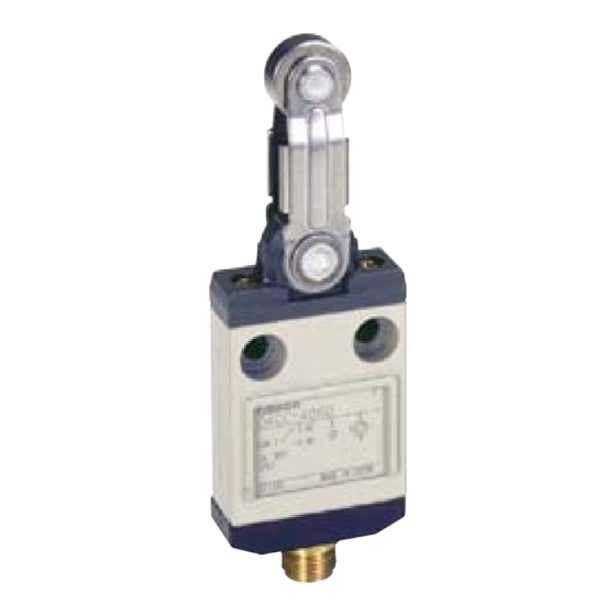
Miniature Limit Switch
D4CC
Many Models Including Roller Lever
Switches are Only 16-mm Thick with
Connector
■ New center roller lever models that enable ganged mounting of up to 6 Switches.
■ Cable connectors for easy Switch replacement.
■ Triple-seal construction for plungers to provide IEC IP67 degree of protection.
■ Operation indicators available for easy monitoring (standard indicator
is lit when Switch is not operating).
■ Approved by UL and CSA.
(Ask your OMRON representative for Information on approved models.)
Model Number Structure
Model Number Legend
D4CC-@0@@
(1)
(2)
(1) Rated Current
1 : 1 A at 125 VAC
2 : 1 A at 125 VAC (with LED indicator)
3 : 1 A at 30 VDC
4 : 1 A at 30 VDC (with LED indicator)
Ordering Information
Switches
Limit Switches
Ratings
LED indicator
Actuator
Pin
plunger
Roller
plunger
Crossroller
plunger
High-sensitivity
roller lever
Sealed pin
plunger
Sealed roller
plunger
Sealed crossroller
plunger
Plastic
rod
Center
roller lever
Note: 1. Ask your OMRON representative for Information on approved models.
2. The meaning of suffix codes in the D4CC model numbers is different from that in the D4C model numbers.
3. Refer to the following table for cable plugs.
http://www.ia.omron.com/
(2) Actuator
01 : Pin plunger
02 : Roller plunger
03 : Crossroller plunger
24 : Roller lever
31 : Sealed pin plunger
32 : Sealed roller plunger
33 : Sealed crossroller plunger
50 : Plastic rod
60 : Center roller lever
1 A at 125 VAC
Without indicator
With indicator
Model
D4CC-1001
D4CC-2001
D4CC-1002
D4CC-2002
D4CC-1003
D4CC-2003
D4CC-1024
D4CC-2024
D4CC-1031
D4CC-2031
D4CC-1032
D4CC-2032
D4CC-1033
D4CC-2033
D4CC-1050
D4CC-2050
D4CC-1060
D4CC-2060
Be sure to read Safety Precautions on page 7 to 8 and
Safety Precautions for All Limit Switches.
Without indicator
Model
Model
D4CC-3001
D4CC-3002
D4CC-3003
D4CC-3024
D4CC-3031
D4CC-3032
D4CC-3033
D4CC-3050
D4CC-3060
(c)Copyright OMRON Corporation 2007 All Rights Reserved.
1 A at 30 VDC
With indicator
Model
D4CC-4001
D4CC-4002
D4CC-4003
D4CC-4024
D4CC-4031
D4CC-4032
D4CC-4033
D4CC-4050
D4CC-4060
1
Advertisement
Table of Contents

Related Manuals for Omron D4CC-1001


Summary of Contents for Omron D4CC-1001
- Page 1 D4CC-4060 roller lever Note: 1. Ask your OMRON representative for Information on approved models. 2. The meaning of suffix codes in the D4CC model numbers is different from that in the D4C model numbers. 3. Refer to the following table for cable plugs.
-
Page 2: Specifications
D4CC-1, D4CC-2 Note: The above figures are initial values. D150 *1. The values are calculated at an operating temperature of +5°C to +35°C, and an operating humidity of 40% to 70%RH. Contact your OMRON sales Current (A) Volt-amperes (VA) Rated... - Page 3 Note: Colors in parentheses are the previous wire colors. Wire colors have been changed accompanying changes in standards. For AC For DC Plug Plug Cable Cable Pin No. Pin No. Brown (Red) Brown (Red) White (Orange) White (Orange) Blue (Black) Blue (Black) Black (White) Black (White) http://www.ia.omron.com/ (c)Copyright OMRON Corporation 2007 All Rights Reserved.
- Page 4 Movement Differential max. 0.2 mm 0.2 mm 0.2 mm 3° 0.2 mm Operating Position 15.7±1 mm 28.5±1 mm 28.5±1 mm 24.9±1 mm Total travel (5) mm * The TT is a reference value. http://www.ia.omron.com/ (c)Copyright OMRON Corporation 2007 All Rights Reserved.
- Page 5 For AC Model For DC Model XS2F-A421-@90-A (For AC) XS2F-A421-C90-A XS2F-D421-C80-A XS2F-A421-D90-A XS2F-D421-D80-A XS2F-A421-G90-A XS2F-D421-G80-A XS2F-A421-J90-A XS2F-D421-J80-A 45 ° 45 ° 6 dia. 5 dia. 5 dia. 14.9 dia. (For DC) (For AC) 40.7 http://www.ia.omron.com/ (c)Copyright OMRON Corporation 2007 All Rights Reserved.
- Page 6 There is no difference in mounting pitch between the Mounting Plate and the WL. The mounting depth of the D4CC with the Mounting Plate attached is, however, shorter than that of the panel-mounted WL. http://www.ia.omron.com/ (c)Copyright OMRON Corporation 2007 All Rights Reserved.
-
Page 7: Safety Precautions
* By removing the two screws from the head, the head direction can be rotated 180°. After changing the head direction, re-tighten to the torque specified above. Be careful not to allow any foreign substance to enter the Switch. http://www.ia.omron.com/ (c)Copyright OMRON Corporation 2007 All Rights Reserved. - Page 8 • If failures, such as reset failures, in the plunger model are possible, use a model that has a rubber cap. • Do not expose the Switch to water exceeding 70°C or use it in steam. http://www.ia.omron.com/ (c)Copyright OMRON Corporation 2007 All Rights Reserved.
-
Page 9: Precautions For Safe Use
Limit Switch itself may become damaged or burnt. Precautions for Correct Use For details, refer to Precautions for Correct Use in the Technical Guide for Limit Switches. http://www.ia.omron.com/ (c)Copyright OMRON Corporation 2007 All Rights Reserved. - Page 10 • If the load is a minute voltage or current load, use a dedicated Switch for minute loads. The reliability of silver-plated contacts, which are used by standard Switches, will be insufficient if the load is a minute voltage or current load. http://www.ia.omron.com/ (c)Copyright OMRON Corporation 2007 All Rights Reserved.
- Page 11 = 0.5 × 10 –6 /operations indicates that the estimated malfunction rate is less than 1/2,000,000 operations with a reliability Unusable range level of 60%. 1 mA 100 mA 160 mA 1,000 Current (mA) http://www.ia.omron.com/ (c)Copyright OMRON Corporation 2007 All Rights Reserved.
-
Page 12: Operating Environment
Otherwise, sulfuric film will be generated on the contacts and contact failures may result. Use the Switch with gold- plated contacts or use a dedicated Switch for minute loads instead. http://www.ia.omron.com/ (c)Copyright OMRON Corporation 2007 All Rights Reserved. - Page 13 (including the environment and operating frequency) to If the dog touches the lever as shown below, the operating position confirm that no problems will occur in actual. will not be stable. Incorrect Correct http://www.ia.omron.com/ (c)Copyright OMRON Corporation 2007 All Rights Reserved.
- Page 14 • When using a pin-plunger actuator, make sure that the stroke of the actuator and the movement of the dog are located along a single straight line. Incorrect Correct Operating Operating body body http://www.ia.omron.com/ (c)Copyright OMRON Corporation 2007 All Rights Reserved.
- Page 15 0.5 to 0.7 (TT) Note: The above y values indicate the ratio ranges based on TT (total travel). Therefore, the optimum pressing distance of the dog is between 50% and 80% (or 50% and 70%). http://www.ia.omron.com/ (c)Copyright OMRON Corporation 2007 All Rights Reserved.
-
Page 16: Maintenance And Repairs
Therefore, reset may be delayed or reset may fail if the Switch is used with the actuator continually pressed in. Contact your OMRON representative if the Switch is to be used for this type of environment or application. - Page 17 Warranty and Limitations of Liability WARRANTY OMRON's exclusive warranty is that the products are free from defects in materials and workmanship for a period of one year (or other period if specifi ed) from date of sale by OMRON. OMRON MAKES NO WARRANTY OR REPRESENTATION, EXPRESS OR IMPLIED, REGARDING NON-INFRINGEMENT, MERCHANTABILITY, OR FITNESS FOR PARTICULAR PURPOSE OF THE PRODUCTS.
Need help?
Do you have a question about the D4CC-1001 and is the answer not in the manual?
Questions and answers