Table of Contents
Advertisement
Quick Links
Installation Manual
H3C S3610 Series Ethernet Switches
Chapter 1 Product Overview ........................................................................................................ 1-1
1.1 Introduction ........................................................................................................................ 1-1
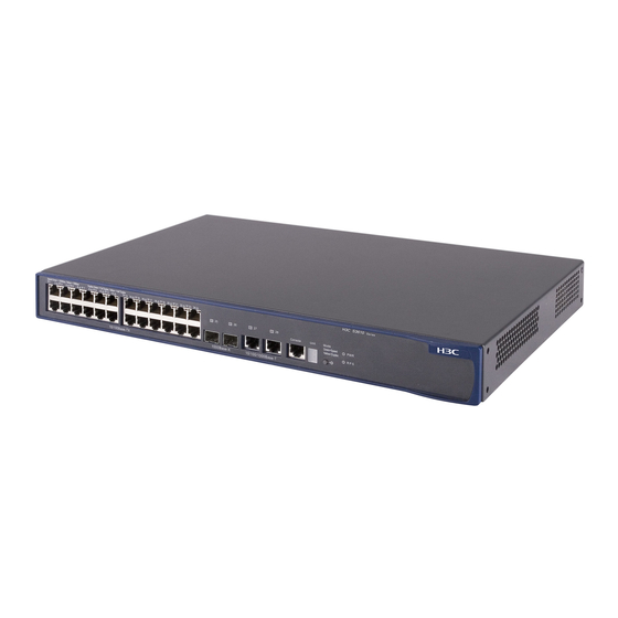
1.2 S3610-28TP Ethernet Switch ............................................................................................ 1-2
1.2.1 Front Panel.............................................................................................................. 1-2
1.2.2 Rear Panel .............................................................................................................. 1-8
1.2.3 Power Supply System ............................................................................................. 1-9
1.3 S3610-28P Ethernet Switch............................................................................................... 1-9
1.3.1 Front Panel.............................................................................................................. 1-9
1.3.2 Rear Panel ............................................................................................................ 1-13
1.3.3 Power Supply System ........................................................................................... 1-13
1.4 S3610-28F Ethernet Switch............................................................................................. 1-13
1.4.1 Front Panel............................................................................................................ 1-13
1.4.2 Rear Panel ............................................................................................................ 1-19
1.4.3 Power Supply System ........................................................................................... 1-19
1.5 S3610-52P Ethernet Switch............................................................................................. 1-19
1.5.1 Front Panel............................................................................................................ 1-19
1.5.2 Rear Panel ............................................................................................................ 1-21
1.5.3 Power Supply System ........................................................................................... 1-21
1.6 S3610-52M/S3610-52M-DC Ethernet Switch.................................................................. 1-21
1.6.1 Front Panel............................................................................................................ 1-21
1.6.2 Rear Panel ............................................................................................................ 1-23
1.7 S3610 Series Ethernet Switches System Features......................................................... 1-25
Chapter 2 Installation Preparation............................................................................................... 2-1
2.1 Safety Precautions............................................................................................................. 2-1
2.2 Installation Site................................................................................................................... 2-1
2.2.1 Temperature/Humidity............................................................................................. 2-1
2.2.2 Cleanness ............................................................................................................... 2-2
2.2.3 Electromagnetic Susceptibility ................................................................................ 2-2
2.2.4 Laser Safety ............................................................................................................ 2-3
2.3 Installation Tools ................................................................................................................ 2-3
Chapter 3 Installing the Switch .................................................................................................... 3-1
3.1 Installing a Switch .............................................................................................................. 3-1
3.1.1 Mounting a Switch to a Cabinet .............................................................................. 3-1
3.1.2 Mounting a Switch on a Workbench........................................................................ 3-5
3.2 Connecting the Power Cord and the Ground Wire ............................................................ 3-5
3.2.1 Connecting the AC-Input Power Cord..................................................................... 3-5
3.2.2 Connecting the DC-Input Power Cord .................................................................... 3-6
Table of Contents
i
Table of Contents
Advertisement
Table of Contents

Related Manuals for H3C S3610- 28P


Summary of Contents for H3C S3610- 28P
-
Page 1: Table Of Contents
Installation Manual H3C S3610 Series Ethernet Switches Table of Contents Table of Contents Chapter 1 Product Overview ......................1-1 1.1 Introduction ........................1-1 1.2 S3610-28TP Ethernet Switch .................... 1-2 1.2.1 Front Panel......................1-2 1.2.2 Rear Panel ......................1-8 1.2.3 Power Supply System ..................... 1-9 1.3 S3610-28P Ethernet Switch.................... - Page 2 Installation Manual H3C S3610 Series Ethernet Switches Table of Contents 3.2.3 Connecting the Ground Wire................... 3-9 3.2.4 Multi-power Input....................3-12 3.3 Connecting the Switch to a Console Terminal..............3-12 3.3.1 Console Cable....................... 3-12 3.3.2 Connecting the Console Cable ................3-13 3.4 Installation of the Optional Interface Modules ..............
- Page 3 Installation Manual H3C S3610 Series Ethernet Switches Table of Contents 7.3.1 Module Panel and LEDs ..................7-3 7.3.2 Module Interface Cable ................... 7-4...
-
Page 4: Chapter 1 Product Overview
Chapter 1 Product Overview Chapter 1 Product Overview 1.1 Introduction H3C S3610 Series Ethernet Switches (hereinafter referred to as S3610 series) are wire speed Layer 2/3 Ethernet switches developed by H3C independently. They are intelligent network-manageable switches intended for network environments requiring high performance, dense port distribution, and ease of installation. -
Page 5: S3610-28Tp Ethernet Switch
Installation Manual H3C S3610 Series Ethernet Switches Chapter 1 Product Overview 1.2 S3610-28TP Ethernet Switch 1.2.1 Front Panel I. Illustration On its front panel, the S3610-28TP provides 24 fixed 10Base-T/100Base-TX Ethernet ports, two 1000 Mbps SFP ports, two 10/100/1000Base-T Ethernet ports and one console port, as shown in Figure 1-1. - Page 6 Installation Manual H3C S3610 Series Ethernet Switches Chapter 1 Product Overview Mark Status Meaning Solid green The switch works normally. The switch is running power-on self-test (POST) or is loading software. (1) When running POST, The system displays the number of current POST...
- Page 7 Installation Manual H3C S3610 Series Ethernet Switches Chapter 1 Product Overview Mark Status Meaning The DC input and the AC Solid green part are all normal. The DC input is normal; the DC-input power Solid yellow AC part is abnormal or the AC input is disconnected.
- Page 8 Installation Manual H3C S3610 Series Ethernet Switches Chapter 1 Product Overview Mark Status Meaning The port works at 100 Mbps; Green when it receives/sends data, the LED flashes quickly. The port works at 10 Mbps; when it receives/sends data, Yellow In speed the LED flashes quickly.
- Page 9 Installation Manual H3C S3610 Series Ethernet Switches Chapter 1 Product Overview Mark Status Meaning The port works at 1000 Mbps; when it Green receives/sends data, the LED flashes quickly. The port works at 10/100 Mbps; when it Yellow Speed receives/sends data, the LED flashes quickly.
- Page 10 For specifications of each SFP module, refer to H3C Low-End Series Ethernet Switches Pluggable Module Manual. The available SFP modules may change as time goes by. Contact the H3C marketing or technical support personnel for the latest available SFP modules.
-
Page 11: Rear Panel
Installation Manual H3C S3610 Series Ethernet Switches Chapter 1 Product Overview Table 1-5 Attributes of the 10/100/1000Base-T Ethernet ports Item Description Connector RJ-45 Number of the ports 10/100 Mbps full/half duplex Speed and mode 1000 Mbps full duplex MDI/MDI-X auto negotiation IEEE 802.3u... -
Page 12: Power Supply System
Installation Manual H3C S3610 Series Ethernet Switches Chapter 1 Product Overview 1.2.3 Power Supply System I. AC-input voltage range Rated voltage range: 100 VAC to 240 VAC, 50 Hz or 60 Hz Max voltage range: 90 VAC to 264 VAC, 50 Hz or 60 Hz II. - Page 13 Installation Manual H3C S3610 Series Ethernet Switches Chapter 1 Product Overview Table 1-7 LEDs on the front panel of the S3610-28P Mark Status Meaning The port status LEDs are Speed Solid green showing their current port speeds. Port mode Mode...
- Page 14 Installation Manual H3C S3610 Series Ethernet Switches Chapter 1 Product Overview Mark Status Meaning The DC input and the AC Solid green part are all normal. The DC input is normal; the DC-input Solid yellow AC part is abnormal or the power LED AC input is disconnected.
- Page 15 For specifications of each SFP module, refer to H3C Low-End Series Ethernet Switches Pluggable Module Manual. The available SFP modules may change as time goes by. Contact the H3C marketing or technical support personnel for the latest available SFP modules.
-
Page 16: Rear Panel
Installation Manual H3C S3610 Series Ethernet Switches Chapter 1 Product Overview 1.3.2 Rear Panel The S3610-28P has an AC-input power socket, a DC-input power socket, and a grounding screw on its rear panel, as shown in Figure 1-4. (1) (1)... - Page 17 Installation Manual H3C S3610 Series Ethernet Switches Chapter 1 Product Overview II. LEDs For your convenience to monitor the operation of the switch, the S3610-28F provides one power LED, one DC-input power LED, one port mode switch LED, one 7-segment numerical display, 24 ×...
- Page 18 Installation Manual H3C S3610 Series Ethernet Switches Chapter 1 Product Overview Mark Status Meaning Solid green The switch works normally. The switch is running power-on self-test (POST) or is loading software. (1) When running POST, The system displays the number of current POST...
- Page 19 Installation Manual H3C S3610 Series Ethernet Switches Chapter 1 Product Overview Mark Status Meaning The number of current In the progress of POST item is displayed. POST The number of failed POST item is displayed. POST failure 7-segment Unit The short lines are lighted...
- Page 20 Installation Manual H3C S3610 Series Ethernet Switches Chapter 1 Product Overview Mark Status Meaning The port works at 1000 Mbps; when it Green receives/sends data, the LED flashes quickly. Speed Flashing yellow (at The port fails the POST. 3 Hz) The port is disconnected.
- Page 21 For specifications of each SFP module, refer to H3C Low-End Series Ethernet Switches Pluggable Module Manual. The available SFP modules may change as time goes by. Contact the H3C marketing or technical support personnel for the latest available SFP modules.
-
Page 22: Rear Panel
Installation Manual H3C S3610 Series Ethernet Switches Chapter 1 Product Overview 1.4.2 Rear Panel The S3610-28F has an AC-input power socket, a DC-input power socket, and a grounding screw on its rear panel, as shown in Figure 1-6. (1) AC-input power socket... - Page 23 Installation Manual H3C S3610 Series Ethernet Switches Chapter 1 Product Overview (1) 100 Mbps Ethernet port status LEDs (2) Console port (3) 7-segment numerical display (4) Port mode switch button (5) Port mode switch LED (6) Power LED (7) DC-input power LED...
-
Page 24: Rear Panel
For specifications of each SFP module, refer to H3C Low-End Series Ethernet Switches Pluggable Module Manual. The available SFP modules may change as time goes by. Contact the H3C marketing or technical support personnel for the latest available SFP modules. - Page 25 Figure 1-9 Front panel of the S3610-52M Caution: The interface modules on the front panel of the H3C S3610-52M and S3610-52M-DC are not hot-swappable. To install or remove these modules, you must first power off the switch. For how to install and remove these modules, refer to section 3.4 "Installation of the Optional Interface Modules”.
-
Page 26: Rear Panel
Installation Manual H3C S3610 Series Ethernet Switches Chapter 1 Product Overview 8-port 10Base-T/100Base-TX module 8-port 100 Mbps SFP module Note: For specific description on the interface modules, refer to Chapter 7 “Optional Interface Modules” in page 7-1. IV. Console port The S3610-52M/S3610-52M-DC switch provides an EIA/TIA-232-compliant console port. - Page 27 Installation Manual H3C S3610 Series Ethernet Switches Chapter 1 Product Overview (1) Grounding screw (2) DC-input power socket (3) RPS DC-input redundancy power socket (4) Fixed interface module Figure 1-11 Rear panel of the S3610-52M-DC Rated voltage range: –48 VDC to –60 VDC Max voltage range: –36 VDC to –72 VDC...
-
Page 28: S3610 Series Ethernet Switches System Features
Installation Manual H3C S3610 Series Ethernet Switches Chapter 1 Product Overview 1.7 S3610 Series Ethernet Switches System Features Table 1-11 S3610 series Ethernet switches system features Item H3C S3610 series S3610-52P S3610-28P 43.6 × 440 × 260 mm (1.7 × 17.3 Physical ×... - Page 29 Installation Manual H3C S3610 Series Ethernet Switches Chapter 1 Product Overview Item H3C S3610 series S3610-52P 45 W S3610-28P 35 W Power S3610-28TP 40 W consumption (fully loaded) S3610-28F 60 W S3610-52M/S3610-52M-DC 110 W Operating 0°C to 45°C (32°F to 113°F)
-
Page 30: Chapter 2 Installation Preparation
Installation Manual H3C S3610 Series Ethernet Switches Chapter 2 Installation Preparation Chapter 2 Installation Preparation 2.1 Safety Precautions To avoid any device impairment and bodily injury caused by improper use, observe these rules: Before cleaning the switch, unplug the power plug of the switch first. Do not clean the switch with wet cloth or liquid. -
Page 31: Cleanness
Installation Manual H3C S3610 Series Ethernet Switches Chapter 2 Installation Preparation because it accelerates aging of insulation materials and can thus significantly lower reliability and service life of your switch. 2.2.2 Cleanness Dust is a hazard to the operating safety of your device. The dust accumulated on the chassis can be adsorbed by static electricity and result in poor contact of metal connectors or metal contact points. -
Page 32: Laser Safety
Installation Manual H3C S3610 Series Ethernet Switches Chapter 2 Installation Preparation Keep the device far from radio transmitting stations, radar stations, and high-frequency devices. Use electromagnetic shielding when necessary, for example, use shielded interface cables. Route interface cables only indoors to prevent signal ports from getting damaged by overvoltage or overcurrent caused by lightning strikes. -
Page 33: Chapter 3 Installing The Switch
Chapter 3 Installing the Switch Caution: When you ask your sales agent to maintain the switch, you must ensure that the H3C dismantlement-preventive seal on a mounting screw of the switch chassis is intact. If you want to open the chassis, you should contact the agent for permission. Otherwise, you will bear any consequence resulted from your actions without permission. - Page 34 Installation Manual H3C S3610 Series Ethernet Switches Chapter 3 Installing the Switch (1) Screw hole used to fix the mounting ear to the cabinet (Use one M6 screw) (2) Screw hole used to fix the switch to the mounting ear Figure 3-1 Appearance of a standard front mounting ear II.
- Page 35 Installation Manual H3C S3610 Series Ethernet Switches Chapter 3 Installing the Switch Wear an ESD-preventive wrist strap to check the grounding and stability of the cabinet. Take out the screws which are packed together with the front mounting ears, and fix one end of mounting ears to the switch, as shown in Figure 3-3.
- Page 36 Installation Manual H3C S3610 Series Ethernet Switches Chapter 3 Installing the Switch Place the switch on the tray horizontally, slide the tray into the cabinet, and fix the other end of mounting ears to the front brackets with crews and captive nuts, as shown in Figure 3-4.
-
Page 37: Mounting A Switch On A Workbench
Installation Manual H3C S3610 Series Ethernet Switches Chapter 3 Installing the Switch Fix the other end of front mounting ears to the front brackets of the cabinet with M6 screws and captive nuts and ensure that the front mounting ears and guide rails have fixed the switch in the cabinet securely, as shown in Figure 3-7. -
Page 38: Connecting The Dc-Input Power Cord
Installation Manual H3C S3610 Series Ethernet Switches Chapter 3 Installing the Switch Figure 3-8 Power socket (recommended) II. Connecting the AC-input power cord Step 1: Connect one end of the chassis ground wire to the grounding screw on the rear of the chassis and the other end to the ground as near as possible. - Page 39 Installation Manual H3C S3610 Series Ethernet Switches Chapter 3 Installing the Switch Step 1: Use a flat-blade screwdriver to loosen screw 1 and screw 2 on the DC input terminal block. Connect DC power terminals of the switch to –48 VDC power supply through DC power cables, with NEG (-) connected to the –48V output of the –48 VDC...
- Page 40 Installation Manual H3C S3610 Series Ethernet Switches Chapter 3 Installing the Switch (1) Air filter (2) Fastening screw Figure 3-11 12V-RPS power socket for an S3610-52M/S3610-52M-DC Ethernet switch Connect one connector of the 12V-RPS DC power cable to the RPS DC power socket of the switch, and the other connector to the corresponding 12 V power output socket of the RPS power module.
-
Page 41: Connecting The Ground Wire
Installation Manual H3C S3610 Series Ethernet Switches Chapter 3 Installing the Switch Connector parts Connector parts Screw 2 Screw 2 Screw 1 Screw 1 Chassis Chassis Figure 3-13 RPS DC-input connector Step 2: Directly insert the connector into DC-input socket on the cabinet, and then fix the screws 1 and 2 carried by the connector itself to the appropriate holes on the cabinet socket using a small flathead screwdriver, see Figure 3-13. - Page 42 Installation Manual H3C S3610 Series Ethernet Switches Chapter 3 Installing the Switch Ground your switch as follows: When a grounding strip is available at the installation site, attach one end of the yellow/green ground wire of the switch to the grounding screw on the grounding strip and fasten the captive nut.
- Page 43 Installation Manual H3C S3610 Series Ethernet Switches Chapter 3 Installing the Switch For an AC-powered switch, if none of the above two conditions is available, ground it through the PE wire of the AC power supply. In this case, make sure this PE wire is well connected to the ground at the power distribution room or AC transformer side.
-
Page 44: Multi-Power Input
Installation Manual H3C S3610 Series Ethernet Switches Chapter 3 Installing the Switch (1) AC/DC power cabinet (2) -48V strip (3) -48V (4) RTN strip (5) RTN (6) PGND strip (7) Grounding (8) Ground wire (9) Grounding screw (10) Ethernet switch... -
Page 45: Connecting The Console Cable
Installation Manual H3C S3610 Series Ethernet Switches Chapter 3 Installing the Switch Figure 3-18 Console cable Table 3-1 Console cable pinouts RJ-45 Signal Direction DB-9 ← ← ← → –– → → → 3.3.2 Connecting the Console Cable Follow these steps to connect a terminal device, a PC for example, to the switch: Step 1: Plug the DB-9 (female) connector of the console cable to the serial port of the PC where the switch is to be configured. -
Page 46: Installation Of The Optional Interface Modules
Note: The descriptions in this section are applicable to the installation and removal of the interface modules on the front panel of the H3C S3610-52M and S3610-52M-DC only. Caution: Before performing any of the following operation, please make sure that the switch is powered off to avoid the damage to the components. -
Page 47: Removal Of Optional Interface Modules
Installation Manual H3C S3610 Series Ethernet Switches Chapter 3 Installing the Switch 3.4.2 Removal of Optional Interface Modules Step 1: Wear ESD wrist strap and disconnect the power of the switch. Step 2: Use a screwdriver to unscrew the captive screws at the both sides of the interface module. -
Page 48: Chapter 4 Starting Up The Switch At The Initial Boot
Installation Manual H3C S3610 Series Ethernet Switches Chapter 4 Starting up the Switch at the Initial Boot Chapter 4 Starting up the Switch at the Initial Boot 4.1 Setting up a Configuration Environment Set up a configuration environment as shown in Figure 4-1. - Page 49 Installation Manual H3C S3610 Series Ethernet Switches Chapter 4 Starting up the Switch at the Initial Boot Figure 4-2 Setting up a new connection Step 2: Enter the name of the new connection in the Name field and click <OK>. The dialog box, as shown in Figure 4-3 displays.
- Page 50 Installation Manual H3C S3610 Series Ethernet Switches Chapter 4 Starting up the Switch at the Initial Boot Data bits = 8 Parity check = none Stop bits = 1 Flow control = none Figure 4-4 Setting communications parameters Step 6: Click <OK>. The HyperTerminal dialogue box appears.
-
Page 51: Booting The Switch
Installation Manual H3C S3610 Series Ethernet Switches Chapter 4 Starting up the Switch at the Initial Boot Step 7: Select File/Properties. Step 8: In the Properties dialog box, select the Settings tab, as shown in Figure 4-6. Step 9: Select VT100 or Auto detect in the Emulation dropdown menu. - Page 52 Ctrl-B to enter Boot Menu... 5” appears. Otherwise, when the waiting time changes from 5 to 0, the system automatically boots up and displays: ************************************************************************** * Copyright (c) 2004-2007 Hangzhou H3C Tech. Co., Ltd. All rights reserved.* * Without the owner's prior written consent, * no decompiling or reverse-engineering shall be allowed.
- Page 53 You can configure the switch now. Note: A wide range of command views are available for H3C Series Switches. For more information on configuration commands and command line interfaces, refer to H3C S3610&S5510 Series Ethernet Switches Operation Manual and H3C S3610&S5510...
-
Page 54: Chapter 5 Loading Boot Rom And Host Software
Installation Manual H3C S3610 Series Ethernet Switches Chapter 5 Loading Boot ROM and Host Software Chapter 5 Loading Boot ROM and Host Software Switch software loading through serial ports in the past is time consuming and cannot be operated remotely. To address these problems, TFTP and FTP are used to allow software and file downloading through Ethernet ports. - Page 55 H3C S3610 Series Ethernet Switches Chapter 5 Loading Boot ROM and Host Software H3C S3610-52P BOOTROM, Version 129 ************************************************************* Copyright (c) 2004-2007 Hangzhou H3C Tech. Co., Ltd. Creation date: Apr 5 2007, 15:47:28 CPU Clock Speed : 200MHz BUS Clock Speed : 33MHz...
-
Page 56: Loading Software From Console Port Using Xmodem
Installation Manual H3C S3610 Series Ethernet Switches Chapter 5 Loading Boot ROM and Host Software 8. Set bootrom password recovery 9. Set switch startup mode 0. Reboot Enter your choice(0-9): 5.2.2 Loading Software from Console Port Using XMODEM I. Introduction to XMODEM XMODEM is a file transfer protocol widely used for its simplicity and good performance. - Page 57 Installation Manual H3C S3610 Series Ethernet Switches Chapter 5 Loading Boot ROM and Host Software 0. Return Enter your choice (0-5): Step 3: Choose an appropriate download baud rate. Enter <5> for example to download at 115200 bps. The system displays the following information:...
- Page 58 Installation Manual H3C S3610 Series Ethernet Switches Chapter 5 Loading Boot ROM and Host Software Figure 5-2 Console Port Configuration dialog box Step 5: Click <Disconnect> to disconnect the HyperTerminal from the switch and then click <Call> to re-establish the connection, thus validating the baud rate setting.
- Page 59 Installation Manual H3C S3610 Series Ethernet Switches Chapter 5 Loading Boot ROM and Host Software Step 6: Press <Enter> to start program loading. The system displays the following information: Now please start transfer file with XMODEM protocol. If you want to exit, Press <Ctrl+X>.
-
Page 60: Loading Software From An Ethernet Port Using Tftp
Installation Manual H3C S3610 Series Ethernet Switches Chapter 5 Loading Boot ROM and Host Software Note: You do not need to reset the HyperTerminal’s baud rate and can skip the last step if you have chosen 9600 bps. In this case, the system does not display the above prompt message but “BootROM is updating now........done!”... - Page 61 Chapter 5 Loading Boot ROM and Host Software Caution: TFTP Server program is not provided with the H3C Series Switches. Step 3: Run terminal emulation program on the PC that is connected to the console port. Start the switch, access the Boot Menu, and then enter the download protocol menu.
-
Page 62: Loading Software From An Ethernet Port Using Ftp
Installation Manual H3C S3610 Series Ethernet Switches Chapter 5 Loading Boot ROM and Host Software 0. Return to boot menu Enter your choice(0-3):3 Select <1>. The subsequent steps are the same as those for loading Boot ROM, except for the program to be downloaded in prompt messages. -
Page 63: Loading Software Remotely
Installation Manual H3C S3610 Series Ethernet Switches Chapter 5 Loading Boot ROM and Host Software Switch IP address ←(This address and the server IP address must be on the same network segment) Server IP address ←(IP address of the PC that stores the file) - Page 64 Installation Manual H3C S3610 Series Ethernet Switches Chapter 5 Loading Boot ROM and Host Software Connected. 220 WFTPD 2.0 service (by Texas Imperial Software) ready for new user User(none):lyt 331 Give me your password, please Password: 230 Logged in successfully [ftp] get SWITCH.app SWITCH.app...
-
Page 65: Loading Software Remotely Using Tftp
Installation Manual H3C S3610 Series Ethernet Switches Chapter 5 Loading Boot ROM and Host Software 5.3.2 Loading Software Remotely Using TFTP TFTP is similar to FTP in remote software downloading. But with TFTP, the switch can only be used as the client to download software to its Flash memory from the TFTP server. -
Page 66: Chapter 6 Maintenance And Troubleshooting
Installation Manual H3C S3610 Series Ethernet Switches Chapter 6 Maintenance and Troubleshooting Chapter 6 Maintenance and Troubleshooting 6.1 Dealing with Loading Failures If software loading fails, the system operates with the original version. To address the failure cause, take these steps: Check that the physical ports are correctly and securely connected. -
Page 67: Recovering The Boot Rom Password
Installation Manual H3C S3610 Series Ethernet Switches Chapter 6 Maintenance and Troubleshooting Enter your choice(0-9): Select <7> and have the switch reboot. The user password is deleted at the reboot to allow you access the switch without password. 6.2.2 Recovering the Boot ROM Password Contact your sales agent for help. -
Page 68: Chapter 7 Optional Interface Modules
Installation Manual H3C S3610 Series Ethernet Switches Chapter 7 Optional Interface Modules Chapter 7 Optional Interface Modules Caution: Invisible rays may emit from the optical interface if the interface is not installed with an optical connector or not covered by a dustproof cover, so you are strongly recommended not to stare at the optical interface. -
Page 69: Module Interface Optical Fiber
Installation Manual H3C S3610 Series Ethernet Switches Chapter 7 Optional Interface Modules Table 7-1 Meaning of LEDs on 8-port 100Base-FX single mode/multi-mode module panel State OFF means that the line is disconnected. ON means the line is LINK connected. OFF means that no data is being transceived. Blinking means data is ACTIVE being transceived. -
Page 70: Module Interface Cable
Installation Manual H3C S3610 Series Ethernet Switches Chapter 7 Optional Interface Modules The description of the panel LEDs is given in the following table: Table 7-3 Meaning of LEDs on 10Base-T/100Base-TX module panel State OFF means that the line is disconnected. ON means the line is LINK connected. - Page 71 Installation Manual H3C S3610 Series Ethernet Switches Chapter 7 Optional Interface Modules The description of the panel LEDs is given in the following table: Table 7-5 Meaning of LEDs on 8-port 100 Mbps SFP module panel State OFF means that the line is disconnected. ON means the line is LINK connected.
Need help?
Do you have a question about the S3610- 28P and is the answer not in the manual?
Questions and answers