
Related Manuals for Unverferth Killbros 735


Summary of Contents for Unverferth Killbros 735
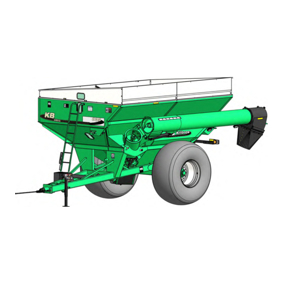
- Page 1 Grain Handling CORNER AUGER GRAIN CART MODEL 735/835 Serial Number D64610100 & Higher Part No. 2007466...
- Page 2 Killbros 735/835 — Introduction Foreword This symbol identifies important safety messages. When you see it, read the message that fol- lows and be alert to the possibility of personal injury. Remember, safety instructions stated in this manual are for your protection.
- Page 3 • Machine name • Model number • Serial number All products manufactured by Unverferth Mfg. Co., Inc. are warranted to be free from ma- terial and workmanship defects for one full year from time of consumer delivery. Your local dealer will gladly assist you with any warranty questions.
-
Page 4: Table Of Contents
Killbros 735/835 — Introduction Table of Contents Section I Safety General Hazard Information ..................1-2 Safety Decals ......................1-3 Following Safety Instructions .................. 1-5 Before Servicing......................1-6 Before Operating....................... 1-6 During Operation....................... 1-6 Before Transporting ....................1-7 During Transport ....................... 1-7 Driveline Safety ...................... - Page 5 Killbros 735/835 — Introduction Table of Contents Section II Set Up Pre-Delivery Checklist ....................2-2 Basic Cart Set Up Folding Side Extensions ..................2-3 Lamp Set Up ....................... 2-4 SMV Emblem ....................... 2-4 Auger Rest Retainer Removal ................2-5 Driveline Storage ....................2-5 Wheel/Tire Set Up ....................
- Page 6 Killbros 735/835 — Introduction Table of Contents Section III Operation Operating Checklist ....................3-2 Preparing Tractor ...................... 3-2 Preparing Cart Hardware ......................3-3 Pivot Pins ......................3-3 Hitch ........................3-3 Auger ........................3-3 Soft Start System ....................3-4 Hydraulic System ....................3-4 Tires/Wheels ......................
- Page 7 Killbros 735/835 — Introduction Table of Contents Section IV Maintenance Lubrication ......................... 4-2 Seasonal Storage ...................... 4-3 Auger Driveline Bearings ....................... 4-4 Gear Box......................4-4 Auger System Lower Auger Disassembly.................. 4-5 Lower Auger Assembly ..................4-6 Upper Auger Disassembly.................. 4-8 Upper Auger Assembly ..................
- Page 8 Killbros 735/835 — Introduction Table of Contents Section V Parts Final Assembly .....................5-2 Touch-Up Paint ....................5-3 Rigid Axle - Single Wheel..................5-4 Adjustable Axle - Single Wheel .................5-6 Adjustable Axle - Dual Wheels................5-8 Track Bundle Components - Model 835 ONLY ...........5-10 Hub &...
-
Page 9: Section I
Killbros 735/835 — Safety Section I Safety General Hazard Information ..................1-2 Safety Decals ......................1-3 Following Safety Instructions .................. 1-5 Before Servicing......................1-6 Before Operating....................... 1-6 During Operation....................... 1-6 Before Transporting ....................1-7 During Transport ....................... 1-7 Driveline Safety ......................1-8 Pressurized Oil ...................... -
Page 10: General Hazard Information
It is true that the designer, the manufacturer, and the safety engineer can help; and they will help, but their combined efforts can be wiped out by a single careless act of the operator. It is said that, “the best kind of a safety device is a careful operator.” We, at Unverferth Mfg. -
Page 11: Safety Decals
Killbros 735/835 — Safety Safety Decals • Replace lost, damaged, painted, oR unReadable decals immediately. if paRts that have decals aRe Replaced, also make suRe to install new DECALS. THESE DECALS INFORM AND REMIND THE OPERATOR WITH OPERATIONAL infoRmation and safety messages. - Page 12 Killbros 735/835 — Safety Safety Decals (continued) SMV PART NO. TA510514 SIS PLATE w/DECAL PART NO. 79342B REFLECTORS 9003125 (Fluorescent) 9003126 (Red) 9003127 (Amber) PART NO. 95046 PART NO. 94754...
-
Page 13: Following Safety Instructions
Killbros 735/835 — Safety Following Safety Instructions • Read and understand this operator’s manual before operating. • All machinery should be operated only by trained and authorized personnel. • To prevent machine damage, use only attachments and service parts approved by the manufac- turer. -
Page 14: Before Servicing
Killbros 735/835 — Safety Before Servicing • Avoid working under an implement; however, if it becomes absolutely unavoidable, make sure the implement is safely blocked. • Ensure that all applicable safety decals are installed and legible. • To prevent personal injury or death, always ensure that there are people who remain outside the cart to assist the person working inside, and that all safe workplace practices are followed. -
Page 15: Before Transporting
Killbros 735/835 — Safety Before Transporting • Secure transport chains to towing vehicle before transporting. DO NOT transport without chains. • Install transport locks before transporting. • Check for proper function of all available transport lights. Make sure that all reflectors are clean and in place on machine. -
Page 16: Driveline Safety
Killbros 735/835 — Safety Driveline Safety • Do not allow children near equipment that is running or engaged. • Do not exceed 1000 rpm PTO speed. • Disengage the PTO, stop the tractor engine, and remove key from ignition before making inspec- tions, or performing maintenance and repairs. -
Page 17: Pressurized Oil
Killbros 735/835 — Safety Pressurized Oil • Relieve the hydraulic system of all pressure before adjusting or servicing. See hydraulic power unit manual for procedure to relieve pressure. • High-pressure fluids can penetrate the skin and cause serious injury or death. Use cardboard or wood to detect leaks in the hydraulic system. -
Page 18: Preparing For Emergencies
Killbros 735/835 — Safety Preparing for Emergencies • Keep a first aid kit and properly rated fire extinguisher nearby. • Keep emergency numbers for fire, rescue, and poison control personnel near the phone. Wearing Protective Equipment • Wear clothing and personal protective equipment appropriate for the job. -
Page 19: Set Up
Killbros 735/835 — Set Up Section II Set Up Pre-Delivery Checklist ....................2-2 Basic Cart Set Up Folding Side Extensions ..................2-3 SMV Emblem ....................... 2-4 Auger Rest Retainer Removal ................2-4 Lamp Set Up ....................... 2-5 Driveline Storage ....................2-5 Wheel/Tire Set Up .................... -
Page 20: Pre-Delivery Checklist
Killbros 735/835 — Set Up Pre-Delivery Checklist After the cart has been completely assembled, use the following checklist and inspect the cart. Check off each item as it is found satisfactory or after proper adjustment is made. o Torque wheel nuts as specified in MAINTENANCE section. -
Page 21: Basic Cart Set Up
Killbros 735/835 — Set Up Basic Set Up Folding Side Extensions Sideboards fig. 2-1 Ladder Downspout Wheels/Tires Jack Due to shipping requirements and various dealer-installed options, some initial cart set up will be required after it arrives from the factory. Use the following procedures as needed for initial cart set up. -
Page 22: Lamp Set Up
Killbros 735/835 — Set Up Basic Set Up (continued) Transport Lighting and Markings Compliance with all lighting and marking laws is the responsibility of the operator at the time of travel. Please see federal regulation 49 CFR 562; available at www.govinfo.gov for US federal law requirements. -
Page 23: Auger Rest Retainer Removal
Killbros 735/835 — Set Up Basic Set Up (continued) Auger Rest Retainer Removal Remove the retainer located on the upper auger rest at the back of the cart, before folding out the upper auger tube. • Upper auger retainer must be removed before operating upper auger tube. -
Page 24: Wheel/Tire Set Up
Killbros 735/835 — Set Up Basic Set Up (continued) Wheel/Tire Set Up Tire Pressure Tire pressure must be verified before first use and adjusted as necessary. Refer to mainte- nance section of this manual for information on tire pressure. Wheel Nuts •... - Page 25 Killbros 735/835 — Set Up Basic Set Up (continued) 1. Hitch cart to tractor. Park the empty unit on a firm, level surface. Set the tractor’s parking brake, shut-off engine and remove the ignition key. 2. Using a safe lifting device and supports rated for a minimum 8 tons, raise cart and support under axle near axle clamps.
- Page 26 Killbros 735/835 — Set Up Notes...
-
Page 27: For Torque Information, Please Refer To The Maintenance Section
Killbros 735/835 — Operation Section III Operation Operating Checklist ....................3-2 Preparing Tractor ...................... 3-2 Preparing Cart Hardware ......................3-3 Pivot Pins ......................3-3 Hitch ........................3-3 Auger ........................3-3 Soft Start System ....................3-4 Hydraulic System ....................3-4 Tires/Wheels ......................3-4 Lubrication ......................... -
Page 28: Operating Checklist
Killbros 735/835 — Operation Operating Checklist o Read and understand all safety precautions before operating cart. Check axle spacing to be sure axle is adjusted from shipping position to desired operating width. (If Applicable) Check to be sure all the reflective decals and the SMV sign are clearly visible with the cart attached to the tractor. -
Page 29: Preparing Cart
Killbros 735/835 — Operation Preparing Cart Perform the service checks as outlined below. Repair or replace any damaged or worn parts before operating. Hardware Check for loose bolts and nuts, and tighten as needed. Check again after the first half-day of operation. -
Page 30: Soft Start System
Killbros 735/835 — Operation Preparing Cart (continued) Soft Start System Check for wear or damage. Lubricate as recommended. Do not over lubricate. Hydraulic System Check all hoses and cylinders for signs of leakage. Hoses should not be kinked, twisted or rubbing against sharp edges. -
Page 31: Hitching To Tractor Drawbar Connection
Killbros 735/835 — Operation Hitching to Tractor Drawbar Connection This cart is intended to be hitched to a tractor draw- bar. Do not attempt to hitch to any other location on the tractor other than the drawbar. The cart is equipped standard with a single tang hitch. -
Page 32: Transport Chain Connection
Killbros 735/835 — Operation Hitching to Tractor (continued) Transport Chain Connection • always use tRanspoRt chain when tRanspoRting implements. failuRe to use a tRanspoRt chain could cause peRsonal inJuRy if caRt becomes disengaged. Always use intermediate chain support when connecting the grain cart directly to a tractor. -
Page 33: Hydraulic Connections For Hydraulic Drive
Killbros 735/835 — Operation Hitching to Tractor (continued) Clean hydraulic hose couplers before connecting to the tractor. For convenience, it is recom- mended to connect the flow door circuit hoses to tractor implement coupler #1, auger spout circuit hoses to coupler #2, and attach auger fold circuit to coupler #3. -
Page 34: Electrical Connections
Killbros 735/835 — Operation Hitching to Tractor (continued) Electrical Connections This cart is equipped with a seven-pin SAE con- nector plug which will connect with the receptacle found on most newer tractors. If your tractor does not have this type of receptacle, an SAE J-560 seven-point socket can be purchased from your Killbros dealer (Part number 92824). -
Page 35: Towing
Killbros 735/835 — Operation Towing This cart is not equipped with brakes. Ensure that the towing vehicle has adequate weight and braking capacity to tow this implement. See the towing vehicle manual for towing ca- pacity. Never tow a loaded grain cart over public roads. -
Page 36: Auger Operation Pto-Driven Auger
Killbros 735/835 — Operation Auger Operation PTO Driven Auger • electRocution will cause seRious inJuRy oR death. the gRain caRt is not insulated. keep away fRom all electRi- CAL LINES AND DEVICES. ELECTROCUTION CAN OCCUR WITHOUT DIRECT CONTACT. • entanglement with the dRiveline will cause seRious inJuRy oR death. -
Page 37: Optional Equipment Hydraulic Drive
Killbros 735/835 — Operation Optional Equipment Hydraulic Drive The optional hydraulically-driven auger permits FIG. 9 cart operation using tractors that are not equipped with a PTO. However, due to the power requirements of a grain cart, it should be expected that a hydraulically-driven grain cart will not unload as quickly as a PTO driven cart. - Page 38 Killbros 735/835 — Operation Optional Equipment (continued) Hydraulic Drive (continued) NOTE: For complete assembly and operation details for the Hydraulic Drive, please refer to the Hydraulic Drive manual (282894). 1. Before loading cart or operating auger, verify that the flow control door is closed.
-
Page 39: Maintenance
Killbros 735/835 — Maintenance Section IV Maintenance Lubrication ......................... 4-2 Seasonal Storage ...................... 4-3 Auger Driveline Bearings ....................... 4-4 Gear Box......................4-4 Auger System Lower Auger Disassembly.................. 4-5 Lower Auger Assembly ..................4-6 Upper Auger Disassembly.................. 4-8 Upper Auger Assembly ..................4-9 Upper Auger Timing ................... -
Page 40: Lubrication
Killbros 735/835 — Maintenance Lubrication To keep your grain cart in top operating condition and to assure its proper performance and reliability for a long period of time, periodic inspection and lubrication is a must. 1 SHOT GREASE WEEKLY SEE CHART... -
Page 41: Seasonal Storage
Killbros 735/835 — Maintenance Seasonal Storage Your cart is an important investment. Spend a little time to protect it from destructive rust and corrosion, You will be repaid in longer service life and better performance. Do the following before placing the cart in storage: 1. -
Page 42: Auger Driveline Bearings
Killbros 735/835 — Maintenance Auger Driveline Bearings It is important to periodically check set screws in all bearings at either end of the driveline for tightness. Gear Box Gear box check/fill plug is located on the right hand front side of the housing. To check oil... -
Page 43: Auger System
Killbros 735/835 — Maintenance Auger System • tuRning augeR and otheR moving paRts can cRush and cut. disengage pto and shut-off engine befoRe seRvicing machine oR enteRing gRain tank, oR opening clean-out DOOR(S). • falling obJects can cause seRious inJuRy oR death. do not woRk undeR the machine at any time while being hoisted. -
Page 44: Lower Auger Assembly
Killbros 735/835 — Maintenance Auger System (continued) Lower Auger Assembly 1. When installing the coupler into the auger Upper Auger fig. 4-2 pipe, the lower auger flighting should be positioned with the driving surface of the drive lobe at a 6:00 position and the flighting... - Page 45 Killbros 735/835 — Maintenance Auger System (continued) Lower Auger Assembly (continued) 4. 5-Pin Drive Bushing Weldment: fig. 4-4 Rotate auger 360 degrees to ensure it is centered on the drive bushing weldment (286436) and the five pins are engaged with auger end.
-
Page 46: Upper Auger Disassembly
Killbros 735/835 — Maintenance Auger System (continued) Upper Auger Disassembly 1. Support the upper auger assembly with a 1 ton hoist and two 1000 lb. straps. 2. Remove auger tube cylinder pin and carefully swing cylinder down without breaking hose connec- tions. -
Page 47: Upper Auger Assembly
Killbros 735/835 — Maintenance Auger System (continued) Upper Auger Assembly 1. Install upper bearing and spring assembly if previously removed. 2. Insert auger in auger tube. Back out bearing setscrews and insert auger stub shaft through bearing. Retain auger with 5/16” x 2” machine screw and nut. - Page 48 Killbros 735/835 — Maintenance Auger System (continued) Upper Auger Assembly Timing Fully extend the upper auger and rotate the auger assembly to ensure both lower and upper augers are engaged. Allow the auger assembly to stop completely, then lower the upper auger approximately 45 degrees, shut off the tractor, remove the keys from the ignition.
-
Page 49: Auger Flow Door Cylinder Replacement
Killbros 735/835 — Maintenance Auger System (continued) Auger Flow Door Cylinder Replacement • neveR enteR caRt with augeR oR tRactoR Running. seRious oR fatal in- JuRy can occuR due to entanglement with Rotating components. always stop engine and Remove key befoRe enteRing caRt. - Page 50 Killbros 735/835 — Maintenance Auger System (continued) Auger Flow Door Cylinder Replacement (continued) 2. On the inside of the cart, open the screen fig. 4-9 service access panel shown in FIG. 4-9. Screen Service Access Panel 3. Remove the cotter pins from the lower cylinder pin then remove the pin.
- Page 51 Killbros 735/835 — Maintenance Auger System (continued) Auger Flow Door Cylinder Replacement (continued) 6. Label the hydraulic hoses to indicate upper and lower. Disconnect them from the cylinder, Remove Lower along with the lower hydraulic fitting (FIG. Hose & Fitting 4-11).
-
Page 52: Verify Telescoping Pto Shaft Length
Killbros 735/835 — Maintenance Verify Telescoping PTO Shaft Length • pRopeRly eXtended and collapsed lengths of the telescoping pto shaft must be veRified befoRe fiRst opeRation with each and eveRy diffeRent tRactoR. if the eXtended length of the pto shaft is not sufficient, it... - Page 53 Killbros 735/835 — Maintenance Verify Telescoping PTO Shaft Length (continued) 4. Hitch tractor drawbar to cart, ensuring that tractor and cart are on level ground and coupled as straight as practical. 5. Connect PTO shaft to tractor, and measure length “L” from same points as used in step 1. Ensure that this measurement does not exceed the maximum recommended extended length calculated in step 3 above.
-
Page 54: Pto Shaft & Clutch
Killbros 735/835 — Maintenance PTO Shaft and Clutch Lubrication (Figs. D1 - D6) Lubricate with quality grease before starting work and every 8 operating hours. Clean and grease PTO driveshaft before each prolonged period of non-use. Molded nipples on the... -
Page 55: Pto Shaft & Clutch
Killbros 735/835 — Maintenance PTO Shaft and Clutch (continued) Coupling the PTO driveshaft (Figs. E1 - E2) Clean and grease the PTO and implement input connection (IIC) AS-Lock 1. Pull locking collar and simultaneously push PTO driveshaft onto PTO shaft until the lock- ing device engages. - Page 56 Killbros 735/835 — Maintenance PTO Shaft and Clutch (continued) Chains (Figs. G1 - G3) NOTE: The chain is intended to prevent the shield from rotating against non-moving parts and there- by preventing shield damage. A properly installed chain will increase the service life of the shield.
- Page 57 Killbros 735/835 — Maintenance PTO Shaft and Clutch (continued) To Dismantle Guard (Figs. J1 - J4) 1. Remove locking screw. 2. Align bearing tabs with cone pockets. 3. Remove half-guard. 4. Remove bearing ring. To Assemble Guard (Figs. K1 - K5) 1.
-
Page 58: Pto Quick Disconnect
Killbros 735/835 — Maintenance PTO Shaft and Clutch (continued) To Assemble Cone (Figs. L1 - L3) 1. Dismantle guard (Figs. J1 - J3). Remove old cone (e.g. cut open with knife). Take off chain. Place neck of new cone in hot water... - Page 59 Killbros 735/835 — Maintenance PTO Quick Disconnect (continued) Quick Disconnect Disassembly 1. Compression Spring 2. Ball 3. Lock Collar 4. Back-up ring 5. Snap ring * Back-up ring * (For some clutch types, place additional back up ring first). Compress lock collar (#3) and remove snap ring (#5).
- Page 60 Killbros 735/835 — Maintenance PTO Quick Disconnect (continued) Clutch Disassembly Tighten the four hex nuts (12) uniformly until the clutch pack and hub are loose. Use special tool 9002007 to bend all four retaining lugs back on the edge of the clutch housing. Remove the thrust plate with Belleville springs to get at the friction disks, drive plates and hub for inspection and service.
- Page 61 Killbros 735/835 — Maintenance Electrical Schematic - Rear Wiring Harness #9003050 Electrical Schematic - Front Wiring Harness #9007460 4-23...
-
Page 62: Hydraulic System Schematic
Killbros 735/835 — Maintenance Electrical Schematic - Coupler #92450 GRAIN CART WIRES White -- Ground Green -- Right amber flashing lamp Yellow -- Left amber flashing lamp Brown -- Tail light Black -- Interior & Auger Lights Red -- Brake Lights... -
Page 63: Wheels And Tires
Killbros 735/835 — Maintenance Wheels and Tires Wheel Nut Torque Requirements • impRopeRly toRQued wheel nuts/bolts can cause a loss of implement contRol and machine damage. toRQue wheel nuts/bolts to values in table. check toRQue befoRe use, afteR one houR of unloaded use oR afteR fiRst load, and each load until wheel nuts/bolts maintain toRQue value. -
Page 64: Tire Pressure
Killbros 735/835 — Maintenance Wheels and Tires (continued) Tire Pressure The following is to be used as a general guide for tire inflation and figures can vary depend- It is important that tires are inspected after ing on specific brand of tire used. -
Page 65: Tire Warranty
Killbros 735/835 — Maintenance Wheels and Tires (continued) Tire Pressure (continued) Tire Pressure for Grain Carts Load Index / Ply Max. PSI Tire Make Part Number Tire Size Rating Titan/Goodyear 94286 23.1x26 R-3 99364 23.1x26 R-1 99307 24.5R32 R-1 169A8/B (5-Star) 94289 24.5x32 R-3... - Page 66 Killbros 735/835 — Maintenance Complete Torque Chart Capscrews - Grade 5 NOTE: • Grade 5 capscrews can be identified by three radial dashes on the head. • For wheel torque requirements, refer to Wheels and Tires. • Tighten U-bolts evenly and equally to have the same number of threads exposed on each end.
- Page 67 Killbros 735/835 — Maintenance Hydraulic Fittings – Torque and Installation SAE FLARE CONNECTION (J.I.C.) 1. Tighten nut with finger until it bottoms the seat. 2. Using a wrench, rotate nut to tighten. Turn nut 1/3 turn to apply proper torque.
-
Page 68: Adjusting Cleanout Door
Killbros 735/835 — Maintenance Adjusting Cleanout Door • moving paRts can cRush and cut. keep away fRom moving paRts. • keep hands cleaR of pinch point aReas. • eye pRotection and otheR appRopRiate peRsonal pRotective eQuipment must be woRn while seRvicing the implement. - Page 69 Killbros 735/835 — Maintenance Adjusting Cleanout Door (continued) 5. Rotate the door wheel to push the gear as- sembly toward bottom of auger to remove Push Gear Assembly excess movement and prevent the door from Toward Bottom of Auger moving upward when unloading the cart. (FIG.
- Page 70 Killbros 735/835 — Maintenance Notes 4-32...
-
Page 71: For Tarp Information, Please Refer To Your Tarp Manual
Killbros 735/835 — Parts Section V Parts Please visit www.unverferth.com/parts/ for the most current parts listing. Please visit www.unverferth.com/parts/ for the most current parts listing. Final Assembly .....................5-2 Touch-Up Paint ....................5-3 Rigid Axle - Single Wheel..................5-4 Adjustable Axle - Single Wheel .................5-6 Adjustable Axle - Dual Wheels................5-8... -
Page 72: Final Assembly
Killbros 735/835 — Parts Final Assembly Please visit www.unverferth.com/parts/ for the most current parts listing. ITEM DESCRIPTION PART NO. QTY. NOTES Window Molding 250431 Bracket, Window Retainer 250461B Ladder Bracket Weldment 251069B Ladder Weldment 280610B Tension Bushing 2” OD x 1.516” ID x 2”... -
Page 73: Touch-Up Paint
Killbros 735/835 — Parts Final Assembly Please visit www.unverferth.com/parts/ for the most current parts listing. ITEM DESCRIPTION PART NO. QTY. NOTES Locknut 1”-8UNC 92199 Window 92403 Capscrew 1/4”-20UNC x 3/4” 9390-003 Grade 5 Capscrew 1/4”-20UNC x 1 1/4” 9390-006 Grade 5 Hex Nut 1/4”-20UNC... -
Page 74: Rigid Axle - Single Wheel
Killbros 735/835 — Parts Rigid Axle — Single Wheel Please visit www.unverferth.com/parts/ for the most current parts listing. - Page 75 Killbros 735/835 — Parts Rigid Axle — Single Wheel Please visit www.unverferth.com/parts/ for the most current parts listing. ITEM DESCRIPTION PART NO. QTY. NOTES Rigid Axle Bundle, Scale =Green= 2006312G Rigid Axle Bundle, Scale =Red= 2006312R Items 1-7 Rigid Axle Bundle, Non-Scale =Green=...
-
Page 76: Adjustable Axle - Single Wheel
Killbros 735/835 — Parts Adjustable Axle — Single Wheels Please visit www.unverferth.com/parts/ for the most current parts listing. - Page 77 Killbros 735/835 — Parts Adjustable Axle — Single Wheels Please visit www.unverferth.com/parts/ for the most current parts listing. PART NO. ITEM DESCRIPTION NOTES 3/4" Stud M22 Stud 4.50” Spindle 4.50” Spindle Adjustable Axle Bundle, Scale =Green= 2007543G 2006348G Adjustable Axle Bundle, Scale =Red=...
-
Page 78: Adjustable Axle - Dual Wheels
Killbros 735/835 — Parts Adjustable Axle — Dual Wheels Please visit www.unverferth.com/parts/ for the most current parts listing. - Page 79 Killbros 735/835 — Parts Adjustable Axle — Dual Wheels Please visit www.unverferth.com/parts/ for the most current parts listing. ITEM DESCRIPTION PART NO. NOTES Adjustable Axle Bundle, Scale =Green= 2006457G Adjustable Axle Bundle, Scale =Red= 2006457R Adjustable Axle Bundle, Non-Scale =Green=...
-
Page 80: Track Bundle Components - Model 835 Only
Killbros 735/835 — Parts Track Bundle Components — Model 835 ONLY Please visit www.unverferth.com/parts/ for the most current parts listing. ITEM ITEM DESCRIPTION PART NO. QTY. NOTES Washer, 7 1/2" 268619 Cover Plate =Black= 268121B Lock Washer, 3/4" 9404-033 Capscrew, 3/4-10UNC x 2 Gr.5... - Page 81 Killbros 735/835 — Parts Track Bundle Components — Model 835 ONLY Please visit www.unverferth.com/parts/ for the most current parts listing. ITEM 6 6 6 6 ITEM DESCRIPTION PART NO. QTY. NOTES Track Axle Bundle, Scale =Green= 2007755G SHOWN Track Axle Bundle, Scale =Red=...
-
Page 82: Hub & Spindle - Single Wheels
Killbros 735/835 — Parts Hub & Spindle — Single Wheels Please visit www.unverferth.com/parts/ for the most current parts listing. PART NUMBER ITEM DESCRIPTION NOTES 3/4" Stud M22 Stud Hub & Spindle Assembly w/out Scales (Green) 280634G 267284G Includes 2 through 16 &... -
Page 83: Hub & Spindle - Straddle Dual
Killbros 735/835 — Parts Hub & Spindle — Straddle Duals Please visit www.unverferth.com/parts/ for the most current parts listing. ITEM DESCRIPTION PART NUMBER QTY. NOTES Hub & Spindle Assembly w/out Scales (Green) 284269G Includes 2 through 15 & 18 Hub & Spindle Assembly w/out Scales (Red) 284269R Hub &... -
Page 84: Single Wheels & Tires
Killbros 735/835 — Parts Single Wheels & Tires Please visit www.unverferth.com/parts/ for the most current parts listing. TIRES For questions regarding new tire war- ranty, please contact your local original equipment tire dealer. Used tires carry no warranty. PART NUMBER... -
Page 85: Dual Wheels & Tires
Killbros 735/835 — Parts Dual Wheels & Tires Please visit www.unverferth.com/parts/ for the most current parts listing. TIRES For questions regarding new tire war- ranty, please contact your local original equipment tire dealer. Used tires carry no warranty. ITEM DESCRIPTION PART NUMBER QTY. -
Page 86: Sideboards - Model 735
Killbros 735/835 — Parts Sideboards — Model 735 Please visit www.unverferth.com/parts/ for the most current parts listing. ITEM DESCRIPTION PART NO. QTY. NOTES Board, Front 280255W Board, Rear 280256W Board, Left Front 251023W Board, Left Rear 251024W Board, Right Front... -
Page 87: Sideboards - Model 835
Killbros 735/835 — Parts Sideboards — Model 835 Please visit www.unverferth.com/parts/ for the most current parts listing. ITEM DESCRIPTION PART NO. QTY. NOTES Board, Left Rear 2007502W Board, Left Front 2007503W Board, Right Front 2007508W Board, Right Rear 2007509W Board, Front... -
Page 88: Decals
Killbros 735/835 — Parts Decals Please visit www.unverferth.com/parts/ for the most current parts listing. 75 MM BLACK TEXT ON WHITE BACKGROUND SCORE LINE PREMASK REQUIRED WHITE BACKGROUND /8" PART NUMBER LOCATED ON BACKING FILM 5-18... - Page 89 Killbros 735/835 — Parts Decals Please visit www.unverferth.com/parts/ for the most current parts listing. ITEM DESCRIPTION PART NO. QTY. NOTES Decal, Danger, Driveshaft Entanglement 95046 Decal, Warning (Read & Understand) 97961 Decal, Warning, Tongue Drop 94094 Decal, Important (Shear-Bolts) 9003574...
-
Page 90: Electrical
Killbros 735/835 — Parts Electrical Please visit www.unverferth.com/parts/ for the most current parts listing. 5-20... - Page 91 Killbros 735/835 — Parts Electrical Please visit www.unverferth.com/parts/ for the most current parts listing. ITEM DESCRIPTION PART NO. QTY. NOTES Tail Light Assembly, Left-Hand 2006223B Includes Items 2, 3A, 4-12, 13A Tail Light Assembly, Right-Hand 2006224B Includes Items 2, 3B, 4-12, 13B...
-
Page 92: Upper Auger
Killbros 735/835 — Parts Upper Auger Please visit www.unverferth.com/parts/ for the most current parts listing. 5-22... - Page 93 Killbros 735/835 — Parts Upper Auger Please visit www.unverferth.com/parts/ for the most current parts listing. ITEM DESCRIPTION PART NO. NOTES Upper Auger Tube Replacement =Green= 2006425G Upper Auger Tube Replacement =Red= 2006425R Quicklinc Fitting 9005073 Tube, Greased Nylon 1/4” OD...
-
Page 94: Lower Auger
Killbros 735/835 — Parts Lower Auger Please visit www.unverferth.com/parts/ for the most current parts listing. 5-24... - Page 95 Killbros 735/835 — Parts Lower Auger Please visit www.unverferth.com/parts/ for the most current parts listing. ITEM DESCRIPTION PART NO. NOTES Spacer Washer 3.25” OD x 1.7813” ID 250393 Rubber Gasket 1/4 x 4 x 4 268217 Cover Plate 268218 Drive Dog Weldment...
-
Page 96: Auger Position Indicator Assembly
Killbros 735/835 — Parts Auger Position Indicator Assembly Please visit www.unverferth.com/parts/ for the most current parts listing. SWITCH BRACKET (281063) FOR REFERENCE ONLY ITEM DESCRIPTION PART NO. QTY. NOTES Auger Indicator Kit 280575 Includes Item #2 Decal, Auger Indicator 9005335... -
Page 97: Cleanout Door Assembly
Killbros 735/835 — Parts Cleanout Door Assembly Please visit www.unverferth.com/parts/ for the most current parts listing. ITEM DESCRIPTION PART NO. QTY. NOTES Door Wheel Weldment 220060B Shaft & Gear Weldment 281062 Door Weldment 281218B Plate, Back Door Lift 281059B Plate, Front Door Lift... -
Page 98: Flow Door Seals
Killbros 735/835 — Parts Flow Door Seals Please visit www.unverferth.com/parts/ for the most current parts listing. OM04229 •Revised 031805-3 ITEM DESCRIPTION PART NO. QTY. NOTES 5-22 Capscrew, 1/4-20UNCx7/8 G5 9390-004 Capscrew, 3/8-16UNCx1 1/2 G5 9390-057 Spring Bracket =Green= 281258G Spring Bracket =Red=... -
Page 99: Drive Components
" 2 " 4 Killbros 735/835 — Parts Drive Components Please visit www.unverferth.com/parts/ for the most current parts listing. ITEM DESCRIPTION PART NO. QTY. NOTES 1 1/2 Flangette Bearing 9003920 Carriage Bolt 1/2-13 x 1 1/4 9388-103 Lock Washer 1/2... -
Page 100: Driveline U-Joint Assembly
Killbros 735/835 — Parts Driveline U-Joint Assembly Please visit www.unverferth.com/parts/ for the most current parts listing. ITEM DESCRIPTION PART NO. QTY. NOTES Complete U-Joint Assembly 95012 Yoke 95010 Grease Zerk, 1/4-28 UNF 91160 Yoke, 1-3/8-6 Spline 95011 Quick Disconnect Pin Kit 92362 Cross &... - Page 101 Killbros 735/835 — Parts Auger Fold Cylinder — 3” x 24” Please visit www.unverferth.com/parts/ for the most current parts listing. ITEM DESCRIPTION PART NO. QTY. NOTES 3" x 24" Cylinder, Complete 280921 Tie Rod Seal Kit 9004382 Flow Control Door Cylinder — 2 1/2” x 36”...
-
Page 102: Hydraulics
Killbros 735/835 — Parts Hydraulics Please visit www.unverferth.com/parts/ for the most current parts listing. 5-32... - Page 103 Killbros 735/835 — Parts Hydraulics Please visit www.unverferth.com/parts/ for the most current parts listing. ITEM DESCRIPTION PART NO. QTY. NOTES Cylinder, 3 x 24" 9004378 Adapter, 9/16 JICF 3/4 M-O Ring 9004393 .055 Restrictor Adapter, 9/16 JICM x 9/16 M-O Ring 9001495 Elbow, 90°...
-
Page 104: Directional Spout Components
Killbros 735/835 — Parts Directional Spout Components Please visit www.unverferth.com/parts/ for the most current parts listing. 5 5 5 5 ITEM DESCRIPTION PART NO. QTY. NOTES Clamp Top Plate 9003814 Poly Clamp Pair 9003816 Retaining Ring 2" 91178 5-34... - Page 105 Killbros 735/835 — Parts Directional Spout Components Please visit www.unverferth.com/parts/ for the most current parts listing. ITEM DESCRIPTION PART NO. QTY. NOTES Hex Nut/Large Flange 5/16-18UNC 91257 Flat Washer 2" 93974 Capscrew 5/16”-18UNC x 2” G5 9390-034 Capscrew 1/2”-13UNC x 4” G5...
-
Page 106: Pto Assembly Shearbolt Clutch
Killbros 735/835 — Parts PTO Assembly Shearbolt Clutch Please visit www.unverferth.com/parts/ for the most current parts listing. 1 3/4-20 Spline Shown Optional 1 3/8-21 Spline Shown 5-36... - Page 107 Killbros 735/835 — Parts PTO Assembly Shearbolt Clutch Please visit www.unverferth.com/parts/ for the most current parts listing. ITEM DESCRIPTION PART NO. QTY. NOTES PTO Shaft w/Shielding / Shearbolt 9004767 1 3/4-20 Spline PTO Shaft w/Shielding / Shearbolt 9004766 1 3/8-21 Spline (Optional)
-
Page 108: Pto Assembly Friction Clutch
Killbros 735/835 — Parts PTO Assembly Friction Clutch Please visit www.unverferth.com/parts/ for the most current parts listing. Optional 1 3/4-20 Spline Shown Optional 1 3/8-21 Spline Shown 5-38... - Page 109 Killbros 735/835 — Parts PTO Assembly Friction Clutch Please visit www.unverferth.com/parts/ for the most current parts listing. ITEM DESCRIPTION PART NO. QTY. NOTES PTO Shaft w/Shielding / Friction 9004769 1 3/4-20 Spline PTO Shaft w/Shielding / Friction 9004768 1 3/8-21 Spline (Optional)
-
Page 110: Shear Bolt Clutch
Killbros 735/835 — Parts Shear Bolt Clutch Please visit www.unverferth.com/parts/ for the most current parts listing. • USe geNUINe OeM RePLaCeMeNT PaRT. Incorrect part may cause shear function to oc- cur too soon causing inconvenience or too late resulting in damage to driveline and auger components. - Page 111 Killbros 735/835 — Parts Shear Bolt Clutch Please visit www.unverferth.com/parts/ for the most current parts listing. ITEM DESCRIPTION PART NO. NOTES Shear-Bolt Clutch 9004170 Shear Yoke 9003710 Grease Zerk 95256 Ball 95257 Housing, Splined 9003884 Quick Disconnect Pin Kit 92362 Bolt, M10 x 60 Gr.
-
Page 112: Friction Clutch Assembly
Killbros 735/835 — Parts Friction Clutch Assembly Please visit www.unverferth.com/parts/ for the most current parts listing. NOTE: The clutch is preset at the factory and should not require adjustment. See Maintenance section specific clutch information. ITEM DESCRIPTION PART NO. NOTES... -
Page 113: 45 Degree Gear Box
Killbros 735/835 — Parts 45 Degree Gear Box Please visit www.unverferth.com/parts/ for the most current parts listing. ITEM DESCRIPTION PART NO. QTY. NOTES Gear Box, Complete 9002812 Includes Items 1 thru 17 Shaft, Input 9001131 1.8:1 Gear Shaft, Output 9001132 1.8:1 Gear... - Page 114 MANUALS\\2007466////July 2018-0//March 2019-1//September 2019-2//March 2020-3//May 2021-4//August 2022-5...
Need help?
Do you have a question about the Killbros 735 and is the answer not in the manual?
Questions and answers