
Subscribe to Our Youtube Channel
Related Manuals for Radleys Reactor-Ready Lab Reactor


Summary of Contents for Radleys Reactor-Ready Lab Reactor
- Page 1 Reactor-Ready Lab Reactor Including Reactor-Ready Filter Lab Reactor Instructions February 2023 | Issue 13 accelerating chemistry...
-
Page 2: Table Of Contents
Contents 1 INTRODUCTION ............................. 2 2 WARRANTY ..............................2 3 SAFETY GUIDE ............................... 3 4 COMPONENT GUIDE ............................. 4 4.1 R ..........................4 EACTOR EADY CORE SYSTEM 4.2 R ........................5 EACTOR EADY FILTER CORE SYSTEM 5 REACTION AND FILTER VESSEL GUIDE ......................6 6 SET-UP AND OPERATION .......................... -
Page 3: Introduction
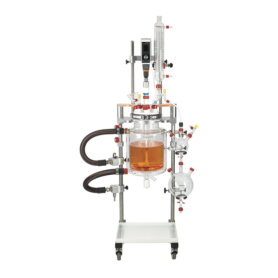
Introduction Thank you for purchasing Reactor-Ready. Please read this instruction manual thoroughly before operating the unit. Reactor-Ready is a flexible benchtop reaction system with a single purpose-built framework that can be used with a wide range of dedicated glass reaction and filter vessels and accessories. It can also be attached to a thermoregulator to allow a fully comprehensive range of heating and cooling operations to be performed. -
Page 4: Safety Guide
Safety guide Please read this safety guide completely before using Reactor-Ready. • Reactor-Ready should only be operated by • Before starting your operation, ensure all trained and competent personnel. As with fittings to the thermoregulator are fully all chemistries, a full risk assessment tightened with no leaks, and that the should be performed prior to starting, and manifold drain and vent valves are closed. -
Page 5: Component Guide
Component guide Reactor-Ready core system Aluminium base (with adjustable feet) HDPE drip tray Support rod bosses Support rods – long (x2) and short (x1) Lower supply manifold (with drain valve)* Upper return manifold (with vent valve) Safety stop collars (x4) Vessel support clamp T-beam support brace Stirrer support I-beam (with sliding boss) -
Page 6: Reactor-Ready Filter Core System
Reactor-Ready filter core system Aluminium base (with adjustable feet) HDPE drip tray Support rod bosses (x3) Extended support rods – long (x2) and short (x1) Lower supply manifold (with drain valve)* Upper return manifold (with vent valve) Safety stop collars (x5) Vessel support clamp T-beam support brace Stirrer support I-beam (with sliding boss) -
Page 7: Reaction And Filter Vessel Guide
Reaction and filter vessel guide For use with the Reactor-Ready core system Reaction vessel kits Process vessel kits Glass reaction vessel with PTFE stopcock Glass process reaction vessel with PTFE stopcock PTFE anchor stirrer PTFE turbine stirrer Pt100 PTFE temperature probe Pt100 PTFE temperature probe PTFE temperature probe adapter PTFE temperature probe adapter... -
Page 8: Set-Up And Operation
Set-up and operation Setting up Reactor-Ready 6.1.1 Requirements • Access to two mains power sockets – one for the thermoregulator and one for the overhead stirrer. • Access to additional mains power sockets if pumps or vacuum pumps are required. •... - Page 9 Step 2 Screw the three support rods into the base. The shortest rod should be positioned in the centre, and the two longer rods on either side. Do not tighten the support rod bosses (locking knobs) at this stage. Note: Filter vessels require extended support rods, so ensure you are using the correct support rods for your application.
-
Page 10: Assembling The Filter Support Plate
Step 4 If using a filter vessel, the filter support plate must be connected to the framework at this point. Note: If a filter vessel is not being used, go straight to Section 6.1.4 – Assembling the manifolds and vessel support clamp (see page 10). 6.1.3 Assembling the filter support plate Step 1... -
Page 11: Assembling The Manifolds And Vessel Support Clamp
6.1.4 Assembling the manifolds and vessel support clamp Useful notes ❖ Reactor-Ready features independent supply and return manifolds to simplify the connection between the thermoregulator and reaction or filter vessel. The manifolds are attached to the support rods and feature precision bore slide bearings. These allow for smooth and independent vertical and horizontal adjustment, providing the flexibility to accommodate different vessel sizes. - Page 12 Important information → The drain valve on the lower supply manifold must be pointing downwards to allow complete drainage of the vessel. → The vent valve on the upper return manifold must be pointing upwards to avoid leakage of thermofluid during drainage of the vessel. Step 3 Slide a safety stop collar onto each of the outer support rods.
-
Page 13: Adding The T-Beam Support Brace And Stirrer Support I-Beam
6.1.5 Adding the T-beam support brace and stirrer support I-beam Step 1 Lower the T-beam support brace onto all three support rods. The rounded top of the central support rod should be just visible above the central hole in the brace. Hand-tighten the three locking knobs. -
Page 14: Locating The Vessel Into The Framework
Locating the vessel into the framework Warning! Only Radleys vessels should be used with Reactor-Ready as they have been specifically engineered to ensure a safe fit and leak-tight seal. Never use vessels from other manufacturers. For further information about Radleys vessels, see Section 7 on page 50. - Page 15 Step 1 Select the appropriate vessel for the chemistry you are peforming. Invert the vessel and place it on a flat surface, ensuring the sidearms are pointing to the right. Undo the bolt on the vessel support collar and place the collar around the neck of the vessel. Note: The opening of the vessel support collar should be facing the front and central (it should be...
- Page 16 Important information → The vessel support collar must be positioned correctly to ensure smooth operation of the vessel support clamp. If after assembling the support collar the vessel is not vertically aligned when located in the clamp, it may be possible to loosen the fastening bolt on the vessel support collar and realign the vessel whilst it is located in the clamp.
-
Page 17: Assembling The Vessel Lid, Stirrer Guide And Stirrer Shaft
6.1.7 Assembling the vessel lid, stirrer guide and stirrer shaft Step 1 Before attaching the glass lid to the vessel, insert the PTFE stirrer guide into the central B24 port on the lid. Hand-tighten the red Rodaviss screw cap to secure the stirrer guide in place. -
Page 18: Clamping The Vessel Lid And Stirrer Assembly To The Vessel
6.1.8 Clamping the vessel lid and stirrer assembly to the vessel Step 1 Assemble the vessel O-ring seal and PTFE O-ring support collar. Place the assembly onto the flange of the vessel neck ensuring that the retaining lip of the O-ring assembly is located in the neck of the vessel. - Page 19 Step 4 Lock the clamp in place with the fastening clip. This is done by hooking the bolt of the fastening clip into the retaining recess of the clamp and then snapping the clip shut. Visual inspection of the O-ring through the opening at the front of the clamp should indicate a witness line where it seals against the lid flange.
-
Page 20: Attaching The Temperature Probe To The Vessel
6.1.9 Attaching the temperature probe to the vessel Step 1 Insert the PTFE temperature probe adapter into the B19 port on the glass lid. Hand-tighten the red Rodaviss screw cap to secure the adapter in place. Partially unscrew the blue locking cap on the top of the probe adapter. -
Page 21: Attaching The Quick-Release Insulated Hoses To The Vessel
6.1.10 Attaching the quick-release insulated hoses to the vessel Important information → Once the quick-release insulated hoses are attached to the vessel, only minor adjustments can be made to the height of the lower supply and upper return manifolds. Step 1 Screw one of the quick-release insulated hoses onto the lower supply manifold, and the other onto the upper return manifold. -
Page 22: Assembling The Overhead Stirrer
6.1.11 Assembling the overhead stirrer Important information → Always refer to the manufacturer’s instructions for your chosen overhead stirrer before using it with Reactor-Ready to be sure of any limitations or safety restrictions. Step 1 Insert the spindle of the stirrer drive coupling into the chuck on your overhead stirrer, and fully tighten the chuck. - Page 23 Useful notes ❖ The sliding boss on the stirrer support I-beam is able to accommodate different sizes of overhead stirrer rods, with the use of removable adapters. With the adapter in place, stirrer rods of up to 13.5mm diameter can be accommodated. Removal of the adapter (by gently prising from the hole with a suitable implement) allows stirrer rods of up to 16.5mm to be used.
- Page 24 Important information → Reactor-Ready features a unique patented rapid stirrer coupling which allows quick and easy alignment of the overhead stirrer with the stirrer guide. However, care should still be taken to ensure alignment is correct. Although some degree of misalignment can be tolerated, correct alignment will enable smooth operation of the stirrer, and reduce wear on the coupling pins.
-
Page 25: Set-Up Instructions For Filter Vessels Only
Set-up instructions for filter vessels only 6.2.1 Assembling the filter plate Important information → Before starting assembly, ensure the filter plate is clean, and that the recess is free of any residues or solid materials. Useful notes ❖ Both PEEK and PTFE filter plates are available for different applications. See page 45 for more details. - Page 26 Step 3 Insert the filter vessel piston into the open end of the BOV glass body. Screw the piston cap onto the thread of the BOV glass body. Important information → Filter vessel pistons are designed specifically for use with filter vessels, and are not interchangeable with reaction vessel pistons.
- Page 27 Important information → Radleys supplies filter membranes suitable for this application (see page 45 for more details). However, if you are using your own filter membrane, ensure it is the correct size and that it fits the filter plate exactly.
-
Page 28: Attaching The Filter Plate Clamp
6.2.2 Attaching the filter plate clamp Step 1 Screw the pin for the filter plate clamp into the inner hole at the rear of the filter support plate. Step 2 Loosen the locking knobs on the filter support plate and gently pivot it until the filter plate is aligned under the filter vessel. - Page 29 Step 5 Do the same with the second part of the clamp, so that it sits on top of the first part. Note: The first part of the clamp must always go on the left-hand side of the support plate. Useful notes ❖...
-
Page 30: Attaching A Collection Vessel
Important information → It is important to obtain a good seal between the filter plate and the filter vessel for maximum filtration performance and to avoid leakages. To achieve the correct tension, adjust the bolt on the clamp fastening by screwing it in or out to increase or decrease the compression force on the seal. - Page 31 Step 2 Insert the tapered joint of the BOV connector into the outlet on the BOV glass body and hand-tighten the red Rodaviss screw cap. Step 3 Place a collection flask on a flat surface. Push a length of PTFE tubing through the central hole in the rubber bung of the collection flask.
- Page 32 Step 5 If required, a cold trap or cold finger can be inserted between the collection flask and vacuum pump. A cold finger will require immersion A cold trap will need filling with a into a dewar with a suitable coolant. coolant, such as dry ice and acetone.
-
Page 33: Converting Reactor-Ready Core To Filter Core
Converting Reactor-Ready core to filter core An existing Reactor-Ready core system that uses reaction vessels can be converted to a filter core system capable of accommodating the full range of Reactor-Ready reaction and filter vessels. To make the conversion, you will first need to fully dismantle your existing Reactor-Ready core system. 6.3.1 Dismantling the Reactor-Ready core system Step 1... -
Page 34: Assembling The Reactor-Ready Filter Core System
6.3.2 Assembling the Reactor-Ready filter core system To assemble the filter core system, you will need all the dismantled components from your Reactor- Ready core system, as well as the following Reactor-Ready upgrade components: 1180mm Extended Filter plate clamp support rod kit DN150 RR170015 RR171004... -
Page 35: Operating Reactor-Ready
Operating Reactor-Ready Before operating Reactor-Ready, please ensure you have read the safety guide on page 3 of this manual. Important information → Reactor-Ready should only be operated by trained and competent personnel. → As with all chemistries, a full risk assessment should be performed prior to starting, and care should be taken to monitor reactions at all stages. -
Page 36: Choosing A Thermoregulator (Circulator)
As a result of in-house testing, Radleys recommends Huber thermoregulators. However, other leading brands such as Lauda, Julabo, Polyscience and Haake are also suitable. -
Page 37: Choosing An Overhead Stirrer
6.4.5 Choosing an overhead stirrer Radleys recommends the use of the Heidolph Hei-TORQUE 200 and 400 Value or Precision overhead stirrers with Reactor-Ready. However, whichever overhead stirrer you choose, always refer to the manufacturer’s instructions before using it with Reactor-Ready to be sure of any limitations or safety restrictions. - Page 38 If using isolating valves and adapters To attach isolating valves, screw the appropriate adapters (if required) onto the lower supply and upper return manifold right-angled connectors, and check that they are fully tightened. Then screw the appropriate isolating valves onto the adapters (if required), and ensure that they are fully tightened.
-
Page 39: Charging Reactor-Ready With Thermofluid
6.4.7 Charging Reactor-Ready with thermofluid Step 1 Ensure the drain valve on the lower supply manifold is closed. Open Closed Useful notes ❖ The lower supply manifold has been upgraded and now features a more compact drain tap, as shown below. Open Closed Step 2... -
Page 40: Draining Thermofluid From Reactor-Ready
Important information → The exact timing for the purge cycle, and the indication that all air has been removed, will be dependent on the thermoregulator being used. Please refer to the manufacturer’s thermoregulator instruction manual for further information. → Always run the purge cycle at ambient temperature to remove any trapped air and to check for thermofluid leaks before applying any heating or cooling. -
Page 41: Disconnecting The Thermoregulator
Important information → Ensure that the thermoregulator has sufficient capacity to collect the full volume of thermofluid. → To achieve full drainage of the vessel, the thermoregulator needs to be at a lower height than the lower sidearm of the reaction vessel. Ideally the thermoregulator should be positioned below the Reactor-Ready assembly. -
Page 42: Connecting The Hose Tidies
Step 2 The hose connectors should now be sealed with the red Rodaviss sealing caps (supplied with the quick- release insulated hoses), or attached to the hose tidies (see Section 6.4.10 below) to prevent dripping of any thermofluid residues. Useful notes ❖... - Page 43 Step 2 To connect the quick-release insulated hoses to the hose tidies, push the PEEK coupling on the hose onto the protruding lug of the hose tidy. A slight twisting motion while pushing the fitting may aid this process. Once the coupling is fully engaged on the lug, screw the red Rodaviss screw cap located onto the hose connector and hand-tighten.
-
Page 44: Static
6.4.11 Static Static can be generated in any circulating fluid system. This is not a fault with the equipment, but an unfortunate and accepted occasional side effect of the methodology. The following is provided for your information only and is not intended to be a definitive guide as to what action to take in the case of static build up. -
Page 45: Filtration
6.4.12 Filtration If using a filter vessel in your Reactor-Ready system, the following points should be noted: • Filter vessels are designed for optimum use in filtration operations to separate a solid from a liquid. The temperature-controlled jacket allows this process to be done under either hot or cold conditions. -
Page 46: Filter Membrane Evaluation Kit
To protect your vacuum pump, and to enhance the performance of your filtration system, it is recommended that you install a cold trap between the collection vessel and your pump, using a Radleys Cold Trap Kit (see page 46). This minimises the amount of vapour entering the pump, thereby protecting the internal components from chemical attack and reducing any residual vapour pressure which may reduce the vacuum achievable. - Page 47 Radleys Cold Trap Kits High Vacuum 500ml Cold Trap Kit Two-piece B34 Cold Trap Kit RR170046 RR170048 Requires the use of a suitable coolant, Requires the use of a dewar flask (not for example acetone and dry ice, in the provided) as well as a suitable coolant chamber of the trap.
- Page 48 Step 2 Connect one end of the tubing to the hose barb on the elbow component. Make sure it is secured tightly to avoid any leakage. Step 3 Place the spray lance in the B34 port of your Reactor-Ready lid. The B34 compression fitting will hold the lance in place during operation.
- Page 49 Filter Cake Catcher Step 1 Ensure that the Filter Plate Assembly is securely clamped to the Filter Vessel as described in Sections 6.1.3 and 6.2.1. Step 2 Place both halves of the Filter Cake Catcher around the Filter Plate, lining up the bottom flaps and the top clips.
- Page 50 Filter Plate Benchtop Support Step 1 The Filter Plate Benchtop Support comes assembled ready for use. Ensure that the M6 screw on the bottom of the Benchtop Support is screwed tightly. Step 2 Clamp the Filter Plate Benchtop Support to a suitable retort stand using the Stainless-Steel rod.
-
Page 51: Jacketed Glass Reaction And Filter Vessels
Jacketed glass reaction and filter vessels Radleys supplies a range of reaction vessels and filter vessels specifically for use with Reactor-Ready. • Reaction vessels are available as single or vacuum jacketed, and range in size from 100ml to 5L. • Filter vessels are single jacketed, and are available in 1L or 2L sizes. - Page 52 (ΔT), should not exceed 50K to avoid the vessel breaking. Temperature range Standard jacketed vessels with the Radleys V4 zero dead space stopcock (see page 52) are suitable for use from -70°C to +230°C. Important information →...
- Page 53 Vessel sidearms Whilst Reactor-Ready hoses are specifically designed to prevent stress being put on the vessel sidearm, care should be taken to avoid stress caused by misaligning or twisting the hoses. Vacuum jacketed vessels Vacuum jacketed vessels are recommended for use with sub-ambient reactions.
- Page 54 If the piston cannot be inserted or removed easily, do not force it. If the piston becomes stuck please contact your local distributor or email sales@radleys.co.uk for technical advice. When closing the V4 ZDS stopcock, the piston will reach the closed position whereupon you will feel resistance.
- Page 55 Periodic replacement of the whole piston assembly may also be required. → The FEP O-rings may not suit all applications, therefore alternative O-ring seals are available. Please email sales@radleys.co.uk for technical advice. When operating at extreme low temperatures (below -50°C) it is recommended that: •...
-
Page 56: General Specifications
General specifications Reactor-Ready core system St r Specifications Weight (framework only) 27kg Thermoregulator hose connector fittings Jacket temperature range -70C to +230C Vessel max Delta-T (temperature difference between vessel jacket and vessel contents) 500rpm continuous Stirrer speed 800rpm for short periods... - Page 57 Reactor-Ready filter core system Specifications Weight (framework only) 30.7kg Thermoregulator hose connector fittings Jacket temperature range -30C to +180C Vessel max Delta-T (temperature difference between vessel jacket and vessel contents) 500rpm continuous Stirrer speed 800rpm for short periods...
- Page 58 Materials of construction Framework support poles Stainless steel 316 1.4401 Stirrer support I-beam Aluminium 6082 HE30, PTFE Vessel support clamp Aluminium 6082 HE30, Stainless steel 316 1.4401, carbon-filled PTFE T beam support plate Aluminium 6082 HE30 Lower supply and upper Aluminium 6082 HE30, Stainless steel 316 1.4401, PTFE return manifolds Reaction vessel...
- Page 59 Filter Cake Catcher Nylon PA12 Spray Lance PTFE Spray Nozzle Stainless steel 316...
-
Page 60: Routine Maintenance
Routine maintenance • To maintain your Reactor-Ready system in prime condition, check all moving parts and seals regularly. • Moving parts should be kept clean and free from any obstructions or surface contamination. Parts relying on sliding motion may benefit from regular application of a thin surface coating of lubricating oil. - Page 61 Warranty – Email Back sales@radleys.com To qualify for your warranty please complete, scan and email this form to Radleys Product Name/Model Product Batch or Serial No. (If shown) Date of purchase Supplier’s name and address Organisation name First name Last name...
- Page 62 Shire Hill, Saffron Walden, Essex, CB11 3AZ, United Kingdom. t: +44 1799 513320 f: +44 1799 513283 © Radleys (R.B. Radley & Co Ltd), 2023 – (E&OE) e: sales@radleys.com...
Need help?
Do you have a question about the Reactor-Ready Lab Reactor and is the answer not in the manual?
Questions and answers