Table of Contents
Advertisement
Advertisement
Table of Contents

Related Manuals for Radleys Reactor-Ready Pilot


Summary of Contents for Radleys Reactor-Ready Pilot
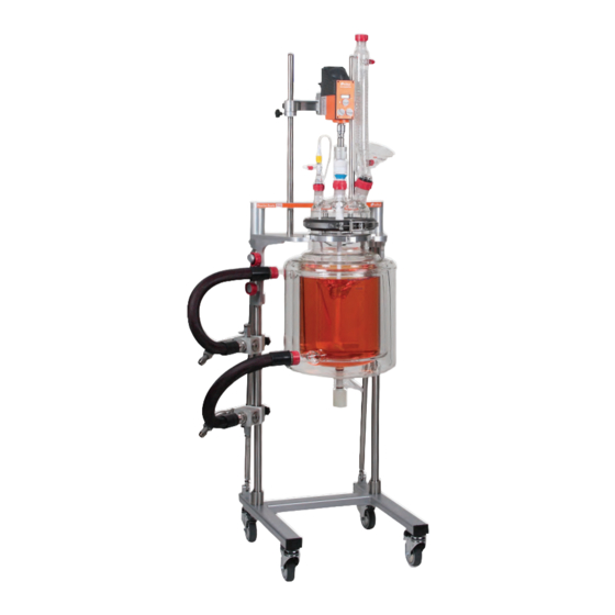
- Page 1 July 2018 Issue 6 Instructions Reactor-Ready Pilot ™ Lab Reactor Patent Pending Your Local Distributor Radleys, Shire Hill, Saffron Walden, Essex, CB11 3AZ. United Kingdom. Tel: +44 1799 513320 Fax: +44 1799 513283 Email: sales@radleys.co.uk Web: www.radleys.com...
-
Page 2: Table Of Contents
8.15 If adapters and isolating valves are not to be used 8.16 If adapters and isolating valves are to be used Page 5 5. Reactor-Ready Pilot and Accessories - Continued 8.17 Charging Reactor-Ready with thermofluid Page 6 5. Reactor-Ready Pilot and Accessories - Continued Page 24 8. -
Page 3: Warranty
1. Introduction Reactor-Ready Pilot is designed as a universal reactor work station that can be used for different vessel sizes and different projects. Reactor-Ready Pilot is ideal for process development, scale-up, pilot and kilo labs. The beauty of Reactor-Ready Pilot is that one reactor work station can replace many, saving you money and fumehood space. -
Page 4: Safety Information
• Reactor-Ready Pilot can be used with a recirculating fluid at a temperature of up to 230˚C, or down to -70°C without damage to the unit. Careful inspection of all fluid connections to Reactor-Ready Pilot should be regularly performed when operating at these temperatures. -
Page 5: Reactor-Ready Pilot And Accessories
• FEP flange O-Ring and PTFE centering collar. HB9328 M24x1.5 x 3m Insulated PTFE Hose -60°C to +260°C Important: Hoses to connect the Reactor-Ready Pilot framework to your thermoregu- HB9612 M30x1.5 x 1m Insulated PTFE Hose -60°C to +260°C M30 Insulated Hose with PTFE Inner (20mm ID x 44mm OD) lator are NOT included. - Page 6 Important: For assistance in identifying the accessories you require or a custom glass- RR139083 PTFE Flexible Bellows B34 ware quote please contact your local Radleys distributor or call Tel: +44 1799 513320. RR139025 Gas Purge Adapter B24 + GL14 + fittings US ‘A Length Joints’.
- Page 7 Important: Designed to reduce the overall height of the Pilot Core by 200 or 300mm. Important: Support collar is required to support vessels within the quick-release clamp. One support collar is supplied with each Reactor-Ready Pilot Core. General Maintenance Accessories We recommend one support collar per vessel.
-
Page 8: Component And Vessel Guide
Reactor-Ready Pilot - Lab Reactor 6. Component and Vessel Guide Reactor-Ready Core System Base Frame Assembly Support Rods Vessel Support Platform Vessel Clamp Vessel FEP O-Ring seal and PTFE centering collar DN200 Vessel Collar + PTFE Liner Brace Bars Stirrer Support Rods Stirrer Support I-Beam 10. - Page 9 Reactor-Ready Pilot - Lab Reactor 6. Component and Vessel Guide - Continued RR236000 - 6 Neck DN200 Lid RR236002 - 7 Neck DN200 Lid • 1 x B34 central vertical - stirrer • 1 x B34 central vertical - stirrer •...
- Page 10 Reactor-Ready Pilot - Lab Reactor 6. Component and Vessel Guide - Continued Single jacket Popular choice, best suited for heating only applications. 5 litre 10 litre 15 litre 20 litre Single Jacketed Single Jacketed Single Jacketed Single Jacketed Vessel Vessel...
- Page 11 Do NOT tighten the locking screws. stirrer. Reactor-Ready Pilot should not be moved after assembly so take care to locate it in its final position. Position the base on a flat surface.
- Page 12 Reactor-Ready Pilot - Lab Reactor 7. Quick Start Guide - Continued 7.7 Slide two safety stop collars on to the 7.8 Assemble the Vessel Support Collar with 7.9 Position the glass reactor on the vessel stirrer support rods, one on each rod, PTFE Liners onto the vessel neck and tight- support platform.
- Page 13 7.19 Connect the thermoregulator Inlet and into the hole in the sliding boss on the Stirrer by loosening the locking knobs, and sliding Outlet hoses to the Reactor-Ready Pilot Support I-Beam. the Stirrer Support I-Beam down so that the Lower Supply Manifold and Upper Return pins of the Stirrer Drive Coupling engage with Manifold.
-
Page 14: Optimising Thermal Performance
Warning - Always refer to the manufacturers specifications for the therm- ofluid before using it with Reactor-Ready Pilot to be sure of any limitations or safety restrictions. Warning - Always refer to the manufacturer’s operating instructions for your thermoregulator before using it with Reactor-Ready Pilot to be sure of any limitations or safety restrictions. -
Page 15: Setting Up The Base
Finally, check that the base is still level, and completely stable on the floor. 8.3.3 Position the Reactor-Ready Pilot Identify a level and clear floor space within your fumehood to site your Reactor-Ready Pilot assembly. You will require two power outlets for an overhead stirrer and thermoregulator, cooling water supply for the reflux condenser, inert gas and vacuum supply for operating under an inert atmosphere. -
Page 16: Assembling The Manifolds
8. Set-Up and Operation - Continued Warning - If using rigid feet with the Reactor-Ready Pilot it is important to 8.3.5 make sure that base is level and stable and the feet locking nuts fully tightened. Failure to observe this may lead to incorrect alignment of framework assembly and reaction vessel, leading to instability and potential damage. -
Page 17: Assembling The Manifolds On The Right Hand Rod
Reactor-Ready Pilot - Lab Reactor 8. Set-Up and Operation - Continued 8.5 Assembling the Manifolds on the right hand rod 8.5.3 If space requirements dictate assembly of manifolds on the right hand rods, fittings on the upper and lower manifolds must be reconfigured. This will require that, counter intuitively, you locate the Upper Return Manifold at the bottom and the Lower Supply Manifold at the top of the right hand rod (the opposite way round to that described in 8.4). -
Page 18: Assembling The Brace Rods
8.7 Assembling the Brace Rods & Leveling the Framework 8.7.1 To provide maximum stability, and to aid alignment, 8.7.1 Reactor-Ready Pilot features adjustable, lockable rear brace bars. The brace bars feature a threaded adjustable fitting, with lock ring, at each end. Fittings have opposite threads, left hand reverse thread is indicated with a groove. -
Page 19: Assembling The Stirrer Support
8.9 Preparing the Reaction Vessel 8.9.2 8.9.1 Reactor-Ready Pilot is capable of supporting a range of dedicated reaction vessels ranging in size from 5 litres to 20 litres in either single jacket or vacuum jacket format. IMPORTANT NOTE - The Reactor-Ready Pilot... -
Page 20: Assembling The Vessel Lid, Stirrer Guide And Probe
Reactor-Ready Pilot - Lab Reactor 8. Set-Up and Operation - Continued 8.9.7 To locate the vessel into the Pilot framework, support with two 8.9.6 hands, slightly tilt the vessel top away from you and carefully locate the lug at the back of the Vessel Support Collar into the central cut-out in the Vessel Support Platform. -
Page 21: Attaching The Thermofluid Hoses
Reactor-Ready Pilot - Lab Reactor 8. Set-Up and Operation - Continued 8.10.7 Close the jaws of the vessel clamp so that they locate around the flange of the vessel 8.10.7 and lid. Hook the bolt of the fastening clip into the retaining recess on the clamp and snap the clip shut;... -
Page 22: Attaching The Overhead Stirrer
Warning - The maximum operating stirring speed for PTFE stirrer guides in general is 500rpm for continuous operation and 800rpm for short periods, but for the large vessel volumes in Reactor-Ready Pilot, slower speeds should be used. Warning - Always refer to the manufacturer’s specifications and instruction manual of your chosen stirrer motor before using it with Reactor-Ready Pilot to be sure of any limitations or safety restrictions. -
Page 23: Choosing Your Thermoregulator (Circulator
8.13 Choosing your thermoregulator (circulator) There are a wide range of thermoregulators available, which are suitable for use with Reactor-Ready Pilot. Choice is determined by factors such as heating and cooling power over the required operating temperature range and work space available. Careful consideration needs to be given to the performance required - fast heating and/or cooling or working at extreme temperatures will not be possible with a low powered thermoregulator. -
Page 24: If Adapters And Isolating Valves Are Not To Be Used
Re-tighten the female swivel coupling. 8.16a If adapters and isolating valves are not to be used Screw the M30 fluid hoses directly onto the Reactor-Ready Pilot Manifold M30 stainless steel 8.15.3 connectors. Ensure that all hoses and connectors remain fully tightened. - Page 25 Reactor-Ready Pilot - Lab Reactor 8. Set-Up and Operation - Continued 8.18 Static Static can be generated in any circulating fluid system. This is not a ‘fault’ with the equipment, but an unfortunate and accepted occasional side effect of the methodology. The following is provided for your information only and is not intended to be a concise guide of necessary actions in the case of static build up.
-
Page 26: Draining Thermofluid From Reactor-Ready Pilot
8.19. Draining thermofluid from Reactor-Ready Pilot 8.19.3 Closed 8.19.1 If the reaction vessel needs to be removed from the Reactor-Ready Pilot framework for cleaning, or to replace it with another vessel, the thermofluid in the jacket must first be drained. -
Page 27: Accessories
Designed to catch spills, a range of optional Polypropylene trays are available in 7, 22 and 45 litre capacities. Simply slide the tray onto the base of Reactor-Ready Pilot from the front using the runners as guides. The tray should sit on top of the base, astride the two base legs with the guides on the underside of the tray sitting parallel within the base legs. -
Page 28: Reflux Dividers
9.4.5 Attach one end of the PTFE tubing to the outlet on the divider head and insert the other end through the fitting in the upper receiving vessel. 9.5 Accessory Glassware A wide range of accessory glassware and clamps to compliment your Reactor-Ready Pilot are available. * Indicates an item is available in other sizes or styles. -
Page 29: Jacketed Glass Reaction Vessels
50K. 10.4 Temperature Range Standard jacketed vessels with the Radleys V4 Zero Dead Space Stopcock, are suitable for use from -70°C to +230°C. (Chemraz O-Rings are recommended for use above +150˚C) Important Note - At temperatures below -50°C and above +150˚C there may be some Important, Important, weeping from the stopcock. -
Page 30: Vacuum Jacketed Vessels
7. Chemraz O-Rings are available for use above 150˚C Closed 10.8.2 The Reactor-Ready Pilot vessel drain valve should only be operated by hand and not with the use of tools. If the piston cannot be inserted or removed easily, do not attempt to force it. -
Page 31: Minimising Weeping At Low Or High Temperatures
Warning - Risk of injury due to broken glass. Never attempt to force the piston when inserting or removing. If the piston becomes stuck please contact your local distributor or email sales@radleys.co.uk for technical advice. 10.9.3 When operating at temperatures below -50°C it is recommended that: a. -
Page 32: General Specifications
Reactor-Ready Pilot - Lab Reactor 11. General Specifications Description Reactor-Ready Jacket Temperature Range -70˚C to +230˚C Hose Fittings M30 x 1.5 Male Weight 27kg 500rpm continuous Stirrer Speed 800rpm for short periods Use slower speeds for large vessel volumes Page 31... -
Page 33: Routine Maintenance
Borosilicate Glass 3.3, 15% Glass Filled PTFE, FEP Encapsulated Silicone (optional Chemraz) 12. Routine Maintenance 12.1 To maintain your Reactor-Ready Pilot system in prime condition it is important that care is taken to check all moving parts and seals regularly. - Page 34 Reactor-Ready Pilot - Lab Reactor 12. Huber Thermoregulator Performance 12. Huber Thermoregulator Performance The following is a guide to the typical heating/cooling times to achieve Process Temperatures for a range of Huber Circulators with a range of reaction volumes. Important Note - These times are based on single jacket reactors, 75% full of a fluid with specific heat capacity 3 kj/kg/˚k.
- Page 35 Warranty – Email Back Reactor-Ready Pilot - Lab Reactor sales@radleys.co.uk To qualify for your warranty please complete, scan and email this form to Radleys Date of Purchase ........................................................ Supplier’s Name and Address .................................................... Product Batch/Serial No. (if shown) ................................................Your Details...
- Page 36 Shire Hill, Saffron Walden, Essex, CB11 3AZ. United Kingdom. t: +44 1799 513320 f: +44 1799 513283 e: sales@radleys.co.uk...
Need help?
Do you have a question about the Reactor-Ready Pilot and is the answer not in the manual?
Questions and answers