Sign In
Upload
Manuals
Brands
Dynojet Manuals
Diagnostic Equipment
200iX
Dynojet 200iX Powersports Chassis Dyno Manuals
Manuals and User Guides for Dynojet 200iX Powersports Chassis Dyno. We have
2
Dynojet 200iX Powersports Chassis Dyno manuals available for free PDF download: Installation Manual
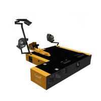
Dynojet 200iX Installation Manual (199 pages)
Ground Model Motorcycle Dynamometer
Brand:
Dynojet
| Category:
Diagnostic Equipment
| Size: 11.11 MB
Table of Contents
Table of Contents
3
Warnings
9
Chapter 1 Specifications and Operating Requirements
13
Introduction
14
Conventions Used in this Manual
15
Technical Support
15
Your Dyno Room
16
Dynamometer Specifications and Requirements
17
Battery Requirements
17
Chassis Specifications
17
Compressed Air Requirements
20
Computer Specifications
20
Drill and Drill Bit Requirements
21
Electrical Requirements
21
Environmental Requirements
21
Forklift Requirements
21
Ground Hook Requirements
21
Grounding Requirements
22
Phone and Internet Access
22
Tie-Down Straps
22
Dynoware RT Electronics
23
Main Module Connections
23
Network Connections
25
Chapter 2 Installation
27
Unpacking and Inspecting the Dyno
28
Dyno Installation
36
Removing the Dyno from the Crate
36
Battery
39
Pickup Card
40
Eddy Current Brake
41
Unpacking the Eddy Current Brake
41
Installing the Eddy Current Brake
45
Installing the Load Cell
48
Secure the Dyno and Brake Module to the Floor
49
Remove the Dyno Covers
50
Drum Module Installation
51
Removing the Items from Crate
51
IX Drum Module Installation
51
Installing the IX Drum Module
53
Installing the Bulkheads
55
Cable Routing
58
Identifying the Cables
58
Installing the Dynoware RT Main Module
60
Routing the Cables
61
Routing the Power Carriage and Wheel Clamp Cables
64
Side and Top Covers
66
Installing the IX Covers
68
Fan Arm Mounts
70
Trike Carriage Adapter and Carriage Assembly
71
Installing the Trike Carriage Adapter Assembly
71
Installing the Carriage Assembly
72
Monitor Support and Tray
75
Control Panel and Cable
76
Final Adjustments and Tests
79
Turning on the Dyno Power
79
High Pressure Blower Test
80
Power Carriage Final Adjustments and Tests
80
Trike Carriage Adapter Assembly Test
80
Wheel Clamp Final Adjustments and Tests
80
Zip Tube
81
Ground Hooks
82
Ramp Bracket
83
Chapter 3 Accessories
88
Main Dyno Power
88
Air Brake
89
Routing the Air Brake Cables and Air Hose
90
Installing the Emergency Stop Sticker
91
Air Brake Final Adjustments and Tests
95
Adjusting the Brake Pad Clearance
95
Air Fuel Ratio Module
102
Extended Carriage
103
Installing the Extended Carriage Assembly
107
High Pressure Blowers
108
Power Carriage
110
Removing the Hand Crank
110
Installing the Power Carriage
111
Wheel Clamp
113
Final Adjustments and Tests
116
Turning on the Dyno Power
116
Power Carriage Final Adjustments and Tests
116
Wheel Clamp Final Adjustments and Tests
116
Chapter 4 Control Panel Interface Operation
117
Introduction
118
Basic CPI Operation
119
Using the Air Fuel Ratio Air Pump
120
Using the Emergency Stop/Dyno Shutdown
121
Using the High Pressure Blowers
121
Understanding Interlocks
121
Using the Power Carriage
122
Using the Starter
122
Using the Status Indicator
123
Using the Wheel Clamp
123
Power Distribution Assembly
125
Main Circuit Breaker
125
High Pressure Blower Circuit Breakers
125
Maintenance and Troubleshooting
126
Maintaining and Troubleshooting the Wheel Clamp
126
Replacing the Eddy Current Brake Driver Fuses
127
Troubleshooting CPI Fuses
128
Chapter 5 Basic Dyno Operation
129
Loading the Vehicle
130
Connecting the RPM Pickup
132
RPM Pickup Descriptions
132
Connecting the Primary Inductive Pickup
133
Grounding the Vehicle
136
Pre-Run Inspection
137
Before Starting the Engine
138
Engine Warm up
138
After Engine Warm up
138
Using the Starter
139
Using the Dyno
139
Making a Test Run
140
Preventative Maintenance
141
Appendix A Red Head Anchor Installation
143
Warnings
143
Contact Information for ITW Ramset/Red Head
143
Appendix B Power Requirements and Installation
147
Power Requirements and Installation-North America, Japan, and Locations Using 60 Hz Power
148
Installing the Wall Receptacle
148
Testing for Correct Voltages
149
Hard Wiring to the Building
150
Power Requirements and Installation-Excluding North America and Japan
151
Installing the Wall Receptacle
152
Testing for Correct Voltages
153
Hard Wiring to the Building
153
Appendix C EEC Kit Installation
155
EEC Finger Guards Installation
155
Removing the Drum Module Hood
156
Installing the EEC Finger Guards
156
Installing the EEC Finger Guards
157
Adjusting the EEC Finger Guards
158
Door Safety Switch
159
Installing the Door Safety Switch
159
Appendix D Folding Ramp Installation
161
Ramp Installation-Dyno
162
Removing the Ramp from the Crate
162
Installing the Ramp on the Dyno
167
Ramp Installation-IX Upgrade
170
Appendix E above Ground Ixw Installation
174
Dynamometer Specifications-Above Ground Ixw Dyno
174
Chassis Specifications
174
Above Ground Ixw Upgrade Installation
177
Removing the Items from Crate
177
Installing the above Ground Ixw Drum Module
180
Installing the Bulkheads
183
Continue Dyno Installation
185
Side and Top Covers-Above Ground Ixw Dyno
186
Continue Dyno Installation
189
Ground Hook Installation-Above Ground Ixw Dyno
190
Appendix F Torque Values
191
Standard Bolt Torque Values
192
Grade 5
192
Grade 8
192
Metric Bolt Torque Values
194
Index
195
Advertisement
Dynojet 200iX Installation Manual (171 pages)
Motorcycle Dynamometers
Brand:
Dynojet
| Category:
Measuring Instruments
| Size: 15.87 MB
Table of Contents
Table of Contents
3
Warnings
9
Specifications and Operating Requirements
13
This Chapter Is Divided into the Following Categories
13
Introduction
14
Conventions Used in this Manual
15
Technical Support
15
Your Dyno Room
16
Battery Requirements
17
Chassis Specifications
17
Dynamometer Specifications and Requirements
17
Compressed Air Requirements
20
Computer Specifications
20
Drill and Drill Bit Requirements
20
Electrical Requirements
20
Environmental Requirements
21
Forklift Requirements
21
Ground Hook Requirements
21
Phone and Internet Access
21
Tie-Down Straps
21
Dyno Electronics
22
Installation
25
Dyno Installation
26
Unpacking the Dyno
26
Removing the Dyno from the Crate
33
Pickup Card
36
Compressed Air Pump Assembly
37
Warnings
37
Compressed Air Requirements
38
Installing the Pump Assembly on the Dyno
38
Installing the Air Hose with the Air Brake
40
Eddy Current Brake
41
Unpacking the Eddy Current Brake
42
Installing the Eddy Current Brake
44
Securing the Drum and Brake Module to the Floor
47
Installing the Theta Controller
48
Remove Dyno Covers
49
Remove the Dyno Covers
49
Drum Module Installation
50
Removing the Items from Crate
50
Installing the IX Drum Module
52
Installing the Bulkheads
54
Routing Cables
58
Battery Requirements
59
Routing the Pendant, RS232 Computer Cable, and Control Panel Cable
61
Wiring the Breakout Board
63
Routing the Power Carriage and Wheel Clamp Cables
64
Side and Top Cover Installation
66
Installing the IX Covers
69
Installing the Trike Carriage Adapter Assembly
71
Trike Carriage Adapter and Carriage Assembly
71
Installing the Carriage Assembly
72
Tie-Down Installation
75
Monitor Support, Tray, and Control Panel
76
High Pressure Blowers
82
Ground Hook Installation
84
Final Adjustments and Tests
85
Turning on the Dyno Power
85
High Pressure Blower Test
86
Power Carriage Final Adjustments and Tests
86
Trike Carriage Adapter Assembly Test
86
Wheel Clamp Final Adjustments and Tests
86
Zip Tube
87
Main Dyno Power
90
Air Brake
91
Routing the Air Brake Cable and Air Hose
91
Installing the Emergency Stop Sticker
93
Air Brake Final Adjustments and Tests
96
Changing the Brake Pads
97
Adjusting the Brake Pad Clearance
103
Compressed Air Pump Assembly
104
Extended Carriage
105
Installing the Extension Support and Trike Carriage Adapter Assembly
105
Installing the Extended Carriage Assembly
107
Power Carriage
108
Removing the Hand Crank
108
Installing the Power Carriage
109
Wheel Clamp
112
Final Adjustments and Tests
116
Power Carriage Final Adjustments and Tests
116
Turning on the Dyno Power
116
Wheel Clamp
116
Wheel Clamp Final Adjustments and Tests
116
Control Panel Interface Operation
117
Basic CPI Operation
118
Using the Air Fuel Ratio Air Pump
119
Understanding Interlocks
120
Using the Emergency Stop/Dyno Shutdown
120
Using the High Pressure Blowers
120
Using the Power Carriage
121
Using the Starter
121
Using the Status Indicator
122
Using the Wheel Clamp
122
High Pressure Blower Circuit Breakers
124
Power Distribution Assembly
124
Maintaining and Troubleshooting the Wheel Clamp
125
Maintenance and Troubleshooting
125
Replacing the Theta Controller Fuses
126
Troubleshooting CPI Fuses
127
Basic Dyno Operation
129
Loading the Vehicle
130
Connecting the RPM Pickup
132
RPM Pickup Descriptions
132
Connecting the Secondary Inductive Pickup
133
Connecting the Primary Inductive Pickup
134
Pre-Run Inspection
135
After Engine Warm up
136
Before Starting the Engine
136
Engine Warm up
136
Making a Test Run
137
Preventative Maintenance
138
Contact Information for ITW Ramset/Red Head
139
Warnings
139
Appendix B Power Requirements and Installation
143
Installation
143
Locations Using 60 Hz Power (North America and Japan
144
Installing the Wall Receptacle
145
Testing for Correct Voltages
146
Replacing the Power Plug
147
Connecting the Dyno
148
Locations Using 50 Hz Power (Locations Other than North America and Japan
149
Installing the Wall Receptacle
150
Testing for Correct Voltages
151
Replacing the Power Plug
152
Connecting the Dyno
153
Appendix C EEC Finger Guard and Door Safety Switch Installation
155
EEC Finger Guards
156
Installing the EEC Finger Guards
158
Adjusting the EEC Finger Guards
160
Door Safety Switch
161
Advertisement
Related Products
Dynojet 250iX
Dynojet 250i
Dynojet 250
Dynojet 200
Dynojet 224
Dynojet 200i
Dynojet 24xLC2 Linx
Dynojet 200iPX
Dynojet 250iPX
Dynojet Wideband 2
Dynojet Categories
Motorcycle Accessories
Automobile Accessories
Control Unit
Measuring Instruments
Controller
More Dynojet Manuals
Login
Sign In
OR
Sign in with Facebook
Sign in with Google
Upload manual
Upload from disk
Upload from URL