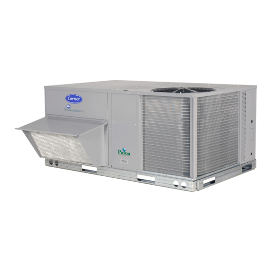
Carrier WeatherMaker 50KCQ A04 Series Installation Instructions Manual
Single package rooftop heat pump with puron r-410a refrigerant
Hide thumbs
Also See for WeatherMaker 50KCQ A04 Series:
- Service and maintenance instructions (80 pages)
Table of Contents
Advertisement
Quick Links
NOTE: Read the entire instruction manual before starting the
installation.
CONTENTS
SAFETY CONSIDERATIONS . . . . . . . . . . . . . . . . . . . 1
MODEL NUMBER NOMENCLATURE AND
DIMENSIONS . . . . . . . . . . . . . . . . . . . . . . . . . . . . . 2
Rated Indoor Airflow (cfm) . . . . . . . . . . . . . . . . . . . . 2
REFRIGERATION SYSTEM COMPONENTS . . . . . . . 9
Typical Unit Piping. . . . . . . . . . . . . . . . . . . . . . . . . . . 9
Reversing Valve and Check Valve Position. . . . . . . 9
Troubleshooting Refrigerant Pressure Problems and
Check Valves . . . . . . . . . . . . . . . . . . . . . . . . . . . . . 9
Refrigerant System Pressure Access Ports . . . . . . 9
INSTALLATION. . . . . . . . . . . . . . . . . . . . . . . . . . . . . . 10
Jobsite Survey . . . . . . . . . . . . . . . . . . . . . . . . . . . . . . 10
Step 1 — Plan for Unit Location . . . . . . . . . . . . . . . . 10
• ROOF MOUNT
Step 2 — Plan for Sequence of Unit Installation . . . 10
• CURB-MOUNTED INSTALLATION
• PAD-MOUNTED INSTALLATION
• FRAME-MOUNTED INSTALLATION
Step 3 — Inspect Unit . . . . . . . . . . . . . . . . . . . . . . . . 11
Step 4 — Provide Unit Support . . . . . . . . . . . . . . . . . 11
• ROOF CURB MOUNT
• SLAB MOUNT (HORIZONTAL UNITS ONLY)
• ALTERNATE UNIT SUPPORT (IN LIEU OF CURB OR
SLAB MOUNT)
Step 5 — Field Fabricate Ductwork . . . . . . . . . . . . . 13
• FOR UNITS WITH ACCESSORY ELECTRIC HEATERS
Step 6 — Rig and Place Unit . . . . . . . . . . . . . . . . . . . 13
• POSITIONING ON CURB
Step 7 — Convert to Horizontal and Connect
Ductwork (if required) . . . . . . . . . . . . . . . . . . . . . . 14
Step 8 — Install Outside Air Hood . . . . . . . . . . . . . . 15
• ECONOMIZER HOOD PACKAGE REMOVAL AND
SETUP – FACTORY OPTION
• ECONOMIZER HOOD AND TWO-POSITION HOOD
Step 9 — Units with Hinged Panels Only . . . . . . . . . 16
Step 10 — Install External Condensate Trap and
Line . . . . . . . . . . . . . . . . . . . . . . . . . . . . . . . . . . . . . 16
Step 11 — Make Electrical Connections . . . . . . . . . 17
• FIELD POWER SUPPLY
• UNITS WITH FACTORY-INSTALLED NON-FUSED
DISCONNECT
• UNITS WITHOUT FACTORY-INSTALLED NON-
FUSED DISCONNECT
• ALL UNITS
• CONVENIENCE OUTLETS
• FACTORY OPTION THRU-BASE CONNECTIONS
• UNITS WITHOUT THRU-BASE CONNECTIONS
• FIELD CONTROL WIRING
• THERMOSTAT
• UNIT WITHOUT THRU-BASE CONNECTION KIT
• HEAT ANTICIPATOR SETTINGS
• COMMERCIAL DEFROST CONTROL
Electric Heaters . . . . . . . . . . . . . . . . . . . . . . . . . . . . . 24
Manufacturer reserves the right to discontinue, or change at any time, specifications or designs without notice and without incurring obligations.
Catalog No. 04-53500213-01
Installation Instructions
Printed in U.S.A.
Form 50KCQ-4-6-02SI Rev. A
Single Package Rooftop Heat Pump
with Puron
®
• SINGLE POINT BOXES AND SUPPLEMENTARY
FUSES
• SINGLE POINT BOXES WITHOUT FUSES
• LOW-VOLTAGE CONTROL CONNECTIONS
Control and Power Wiring Diagrams . . . . . . . . . . . 25
Economi$er® X (Factory Option) . . . . . . . . . . . . . . 30
• SYSTEM COMPONENTS
• SPECIFICATIONS
• INPUTS
• OUTPUTS
• ENVIRONMENTAL
• ECONOMIZER MODULE WIRING DETAILS
• INTERFACE OVERVIEW
• SETUP AND CONFIGURATION
•
ENTHALPY SETTINGS
• CHECKOUT
• TROUBLESHOOTING
Smoke Detectors. . . . . . . . . . . . . . . . . . . . . . . . . . . . 40
• ADDITIONAL APPLICATION DATA
PremierLink™ Controller (Factory Option) . . . . . . 41
RTU Open Controller (Factory-installed Option) . . 41
• CONTROLLER OPTIONS
Step 12 — Adjust Factory-Installed Options . . . . . 42
• SMOKE DETECTORS
• ECONOMI$ER IV OCCUPANCY SWITCH
Step 13 — Install Accessories . . . . . . . . . . . . . . . . . 42
Step 14 — Check Belt Tension . . . . . . . . . . . . . . . . 42
• BELT FORCE — DEFLECTION METHOD
• BELT TENSION METHOD
Pre-Start and Start-Up . . . . . . . . . . . . . . . . . . . . . . . 42
START-UP CHECKLIST . . . . . . . . . . . . . . . . . . . . CL-1
SAFETY CONSIDERATIONS
Installation and servicing of air-conditioning equipment can be
hazardous due to system pressure and electrical components.
Only trained and qualified service personnel should install, re-
pair, or service air-conditioning equipment.
Untrained personnel can perform basic maintenance functions
of cleaning coils and filters and replacing filters. All other op-
erations should be performed by trained service personnel.
When working on air-conditioning equipment, observe precau-
tions in the literature, tags and labels attached to the unit, and
other safety precautions that may apply.
Follow all safety codes, including ANSI (American National
Standards Institute) Z223.1. Wear safety glasses and work
gloves. Use quenching cloth for unbrazing operations. Have
fire extinguisher available for all brazing operations.
It is important to recognize safety information. This is the safe-
ty-alert symbol
. When you see this symbol on the unit and
in instructions or manuals, be alert to the potential for personal
injury.
Understand the signal words DANGER, WARNING, CAU-
TION, and NOTE. These words are used with the safety-alert
symbol. DANGER identifies the most serious hazards which
will result in severe personal injury or death. WARNING signi-
fies hazards which could result in personal injury or death.
Pg 1
11-19
WeatherMaker
50KCQ*04-06
(R-410A) Refrigerant
Replaces: 50KCQ-4-6-01SI
®
Advertisement
Table of Contents

Related Manuals for Carrier WeatherMaker 50KCQ A04 Series


Summary of Contents for Carrier WeatherMaker 50KCQ A04 Series
- Page 1 ® WeatherMaker 50KCQ*04-06 Single Package Rooftop Heat Pump with Puron ® (R-410A) Refrigerant Installation Instructions NOTE: Read the entire instruction manual before starting the • SINGLE POINT BOXES AND SUPPLEMENTARY FUSES installation. • SINGLE POINT BOXES WITHOUT FUSES CONTENTS • LOW-VOLTAGE CONTROL CONNECTIONS SAFETY CONSIDERATIONS .
-
Page 2: Electrical Shock Hazard
CAUTION is used to identify unsafe practices, which may re- sult in minor personal injury or product and property damage. CAUTION NOTE is used to highlight suggestions which will result in en- hanced installation, reliability, or operation. PERSONAL INJURY HAZARD Failure to follow this caution may result in personal injury. - Page 3 11 12 13 15 16 17 18 Packaging and Seismic Compliant 0 = Standard Unit/Series Model 1 = LTL 50KC – Packaged 14 SEER Rooftop Electrical Options A = None C = Non-Fused Disconnect D = Thru-The-Base Connections Q = Heat Pump F = Non-Fused Disconnect and Thru-The-Base Connections Service Options Refrig.
- Page 4 Fig. 2 — Dimensional Drawing for Units Built On and After 4/15/19...
- Page 5 Fig. 3 — Dimensional Drawing for Units Built Prior to 4/15/19...
- Page 6 Fig. 4 — Corner Weights and Clearances...
- Page 7 Fig. 5 — Base Rail Details...
- Page 8 Fig. 6 — Thru-the-Base Charts...
-
Page 9: Refrigeration System Components
REFRIGERATION SYSTEM COMPONENTS Table 2 — Cooling Mode (each circuit) Typical Unit Piping COMPONENT STATUS/POSITION Each heat pump refrigeration system includes a compressor, Reversing Valve Energized accumulator, reversing valve, dual-function outdoor coil with Check Valve A Closed vapor header check valve, cooling liquid line with a filter drier Check Valve B Open and a check valve, dual-function indoor coil with a vapor head-... -
Page 10: Roof Mount
SEAT CORE (Part No. EC39EZ067) 1/2-20 UNF RH 0.596 45° 30° WASHER DEPRESSOR PER AHRI 720 O-RING 1/2” HEX +.01/-.035 5/8” HEX 0.47 FROM FACE OF BODY 7/16-20 UNF RH This surface provides a metal to metal seal when torqued into the seat. Appropriate handling is required to not scratch or dent the surface. -
Page 11: Roof Curb Mount
Table 5 — Operating Weights UNITS LB (KG) UNITS LB (KG) UNITS LB (KG) 50KCQ Base Unit 495 (224) 580 (263) 610 (276) Economizer Vertical 50 (23) 50 (23) 50 (23) Horizontal 80 (36) 80 (36) 80 (36) Cu Fins 25 (11) 43 (20) 56 (25) - Page 12 Fig. 10 — Roof Curb Details...
- Page 13 Step 5 — Field Fabricate Ductwork Step 6 — Rig and Place Unit Cabinet return-air static pressure (a negative condition) shall Keep unit upright and do not drop. Spreader bars are required. not exceed 0.35 in. wg (87 Pa) with economizer or 0.45 in. wg Rollers may be used to move unit across a roof.
- Page 14 Fig. 11 — Rigging Label Step 7 — Convert to Horizontal and Connect Do not cover or obscure visibility to the unit’s informative data plate when insulating horizontal ductwork. Ductwork (when required) Unit is shipped in the vertical duct configuration. Unit without REMOVABLE HORIZONTAL factory-installed economizer or return-air smoke detector op- RETURN DUCT OPENING COVER...
-
Page 15: Economizer Hood And Two-Position Hood
metal tray is attached to the basepan and also attached to the NOTCHES NOTCHES damper using two plastic tie-wraps. To gain access to the hood, remove the filter access panel. (See Fig. 15.) FILTER ACCESS PANEL BASEPAN Fig. 13 — Location of Notches COMPRESSOR ACCESS PANEL SCREWS... - Page 16 PANEL DIVIDER OUTSIDE HOOD CLEANABLE ALUMINUM FILTER FILTER PANEL CAULK HERE BAROMETRIC INDOOR INDOOR RELIEF COIL COIL ACCESS ACCESS FILTER PANEL PANEL CLIP Fig. 19 — Economizer Filter Installation Fig. 17 — Indoor Coil Access Panel Relocation Step 9 — Units with Hinged Panels Only Swing out indoor coil access panel and insert the hood Relocate latch shipped inside the compressor compartment be- sides under the panel (hood top).
- Page 17 The piping for the condensate drain and external trap can be wire size is #2 AWG (copper only). See Fig. 23 and unit label completed after the unit is in place. See Fig. 22. diagram for field power wiring connections. NOTE: TEST LEADS —...
-
Page 18: Units Without Factory-Installed Non-Fused Disconnect
Connect field power supply conductors to LINE side terminals UNITS WITHOUT FACTORY-INSTALLED NON-FUSED when the switch enclosure cover is removed to attach the handle. DISCONNECT When installing units, provide a disconnect switch per NEC (National Electrical Code) of adequate size. Disconnect sizing data is provided on the unit informative plate. - Page 19 and location. Route 125-v power supply conductors into the PWD-CO TRANSFORMER bottom of the utility box containing the duplex receptacle. CONVENIENCE Unit-Powered Type: OUTLET GFCI A unit-mounted transformer is factory-installed to stepdown the main power supply voltage to the unit to 115-v at the du- plex receptacle.
-
Page 20: Factory Option Thru-Base Connections
LOW VOLTAGE CONDUIT CONNECTOR HIGH VOLTAGE CONDUIT Fig. 30 — Convenience Outlet Utilization Notice Label CONNECTOR Convenience Outlet Usage Rating: Continuous usage: 8 amps maximum Test the GFCI receptacle by pressing the TEST button on the Fig. 32 — Thru-Base Connection Fittings (Units Built face of the receptacle to trip and open the receptacle. -
Page 21: Field Control Wiring
(available as factory-installed option or 3. W2 connection not required on units with single-stage heating. Field Wiring as field-installed accessory, for use on a Carrier Comfort Net- work or as a stand-alone control) or the RTU Open Controller Fig. 34 — Low-Voltage Connections... -
Page 22: Heat Anticipator Settings
RACEWAY HOLE IN END PANEL (HIDDEN) SWITCHES Fig. 35 — Field Control Wiring Raceway HEAT ANTICIPATOR SETTINGS Set heat anticipator settings at 0.14 amp for the first stage and SPEED-UP JUMPERS 0.14 amp for second-stage heating, when available. Fig. 36 — Defrost Control Board Arrangement COMMERCIAL DEFROST CONTROL The DFB is located in the 50KCQ’s main control box (see The Commercial Defrost Control Board (DFB) coordinates ther-... - Page 23 Table 6 — 50KCQ Defrost Board I/O and Jumper Configurations CONNECTION POINT NAME TYPE OF I/O UNIT CONNECTION NOTE PIN NUMBER INPUTS G Fan DI, 24 vac P2-3 CTB-G Y1 Cool 1 DI, 24 vac P2-5 CTB-Y1 Y2 Cool 2 DI, 24 vac P2-4 CTB-Y2...
- Page 24 At the end of the unit defrost cycle, the unit will be returned to DISCONNECT MOUNTING Heating cycle for a full continuous run period. If the space LOCATION heating load is satisfied and compressor operation is terminat- ed, the defrost control will remember where the run period was interrupted.
-
Page 25: Single Point Boxes And Supplementary Fuses
SINGLE POINT BOXES AND SUPPLEMENTARY FUSES LOW-VOLTAGE CONTROL CONNECTIONS When the unit MOCP device value exceeds 60-A, unit-mount- Pull the low-voltage control leads from the heater module(s) — ed supplementary fuses are required for each heater circuit. VIO and BRN (two of each if two modules are installed; iden- These fuses are included in accessory single point boxes, with tify for Module #1) —... - Page 26 Fig. 44 — Typical 50KCQ 04-6 Electro-Mechanical Control Wiring Diagram (208/230-v, 460-v Shown)
- Page 27 Fig. 45 — Typical 50KCQ 04-06 Electro-Mechanical Power Wiring (208/230-3-60 Hz shown))
- Page 28 Fig. 46 — Typical 50KCQ 04-06 PremierLink™ Wiring Schematic (208/230-v, 460-v shown)
- Page 29 Fig. 47 — Typical 50KCQ 04-06 RTU Open System Control Wiring Diagram (208/230-v, 460-v shown)
-
Page 30: System Components
® Economi$er X (Factory Option) User Interface Provides status for normal operation, setup parameters, check- The EconoMi$er X system is an expandable economizer con- out tests, and alarm and error conditions with a 2-line 16 char- trol system, which includes a W7220 economizer module (con- acter LCD display and four button keypad. -
Page 31: Economizer Module Wiring Details
Storage Temperature Table 8 — Economizer Module - Left Hand Terminal –40°F to 150°F (–40°C to 65°C) Blocks Shipping Temperature LABEL TYPE DESCRIPTION –40°F to 150°F (–40°C to 65°C) Top Left Terminal Block Relative Humidity 20k NTC Mixed Air Temperature Sensor (Polarity 5% to 95% RH non-condensing and COM Insensitive Connection) -
Page 32: Interface Overview
SENSOR (HOT) BLACK YELLOW ANALOG BROWN – ORANGE GREEN SWITCH POWER SUPPLY. PROVIDE DISCONNECT LABEL MEANS AND OVERLOAD PROTECTION AS REQUIRED. Fig. 51 — CO Sensor Wiring SWITCHES INTERFACE OVERVIEW This section describes how to use the EconoMi$er ® user inter- face for: •... -
Page 33: Setup And Configuration
Press the (Enter) button to display the value of the • CHECKOUT currently displayed item. • ALARMS Press the ▲ button to increase (change) the displayed NOTE: Some parameters in the menus use the letters MA or parameter value. MAT, indicating a mixed air temperature sensor location before Press the ▼... - Page 34 Table 12 — W7220 Menu Structure* (cont) PARAMETER PARAMETER EXPANDED PARAMETER NAME MENU PARAMETER DEFAULT RANGE AND Notes † VALUE INCREMENT OUTSIDE AIR RELATIVE HUMIDITY Displays measured value of outdoor humidity from OA Sylk Bus OA HUM _ _ % 0 to 100% sensor.
- Page 35 Table 12 — W7220 Menu Structure* (cont) PARAMETER PARAMETER EXPANDED PARAMETER NAME MENU PARAMETER DEFAULT RANGE AND Notes † VALUE INCREMENT VENTILATION MINIMUM POSITION MIN POS 2.8 V 2 to 10 vdc Displays ONLY if a CO sensor is NOT connected. DCV MAXIMUM DAMPER POSITION Displays only if a CO sensor is connected.
- Page 36 Table 12 — W7220 Menu Structure* (cont) PARAMETER PARAMETER EXPANDED PARAMETER NAME MENU PARAMETER DEFAULT RANGE AND Notes † VALUE INCREMENT 1000 to 3000 ppm; ppm span to match CO sensor; e.g.: 500-1500 sensor CO2 SPAN 2000ppm Increment by 50 output would be 500 CO zero and 1000 CO span.
- Page 37 Table 12 — W7220 Menu Structure* (cont) PARAMETER PARAMETER EXPANDED PARAMETER NAME MENU PARAMETER DEFAULT RANGE AND Notes † VALUE INCREMENT OA SYLK T ERR OUTSIDE AIR S-BUS SENSOR ERROR Outdoor air enthalpy sensor has failed or become disconnected - OA SYLK H ERR check wiring, then replace sensor if the alarm continues.
- Page 38 Table 13 — Damper Minimum Position Settings and Readings on Checkout Menu DEMAND CONTROLLED VENTILATION FAN SPEED SETPOINTS CHECKOUT SENSOR) MIN POS VMAX–HS VENT MIN VMAX–HS VENT MAX VMAX–HS Table 14 — Dry Bulb Operation without DCV (CO Sensor) — 1 Speed Fan DEMAND OUTSIDE AIR CONTROLLED...
-
Page 39: Enthalpy Settings
Table 17 — Enthalpy Operation with DCV (CO Sensor) — 1 Speed Fan DEMAND OUTSIDE AIR CONTROLLED GOOD TO Y1-I Y2-I Y1-O Y2-O OCCUPIED UNOCCUPIED SPEED VENTILATION (DCV) ECONOMIZE High 0-v/Off 0-v/Off VENTMIN Closed High 24-v/On 0-v/Off VENTMIN Closed High 24-v/On 24-v/On VENTMIN... -
Page 40: Troubleshooting
Figure 53 shows the 5 current boundaries. There is also a high lim- ES1 when there are no stages of mechanical cooling energized and it boundary for differential enthalpy. The high limit boundary is HL (high limit) when a compressor stage is energized. CHECKOUT TROUBLESHOOTING Inspect all wiring connections at the economizer module’s termi-... -
Page 41: Controller Options
PremierLink™ Controller (Factory Option) RETURN AIR SMOKE DETECTOR For details on operating 50KCQ*04-06 units equipped with the (AS SHIPPED) factory-installed PremierLink controller option, refer to the PremierLink Retrofit Rooftop Controller Version 3.x Installa- tion, Start-Up, and Configuration Instructions manual. RTU Open Controller (Factory-installed Option) For details on operating 50KCQ*04-06 units equipped with the factory-installed RTU Open controller refer to the Factory-In- stalled RTU Open Multi-Protocol Controller Control, Start-... -
Page 42: Smoke Detectors
Ensure the blower shaft and motor shaft are parallel to each other (pulleys aligned). Tighten all bolts securely when finished. © 2019 Carrier Corporation Manufacturer reserves the right to discontinue, or change at any time, specifications or designs without notice and without incurring obligations. Catalog No. 04-53500213-01 Printed in U.S.A. -
Page 43: Preliminary Information
UNIT START-UP CHECKLIST (Remove and use for job file) NOTE: To avoid injury to personnel and damage to equipment or property when completing the procedures listed in this start-up checklist, use good judgment, follow safe practices, and adhere to the safety considerations/information as outlined in preceding sec- tions of this Installation Instruction document. - Page 44 © 2019 Carrier Corporation Manufacturer reserves the right to discontinue, or change at any time, specifications or designs without notice and without incurring obligations. Catalog No. 04-53500213-01 Printed in U.S.A. Form 50KCQ-4-6-02SI Rev. A Pg CL-2 11-19 Replaces: 50KCQ-4-6-01SI...
Need help?
Do you have a question about the WeatherMaker 50KCQ A04 Series and is the answer not in the manual?
Questions and answers