Carrier COMFORT 50EZ-A Owner's Information Manual
Comfort and performance 13 and 14 seer single packaged heat pump system with puron (r-410a) refrigerant
Hide thumbs
Also See for COMFORT 50EZ-A:
- Installation instructions manual (32 pages) ,
- Product data (30 pages) ,
- Owner's information manual (4 pages)
Table of Contents
Advertisement
Quick Links
50EZ---A and 50VT ---A
Comfort™ and Performance™ 13 and 14 SEER
Single Packaged Heat Pump System
With PuronR (R ---410A) Refrigerant
Single and Three Phase
2---5 Nominal Tons (Sizes 24---60)
Owner's Information Manual
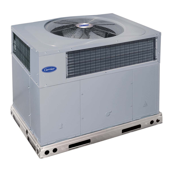
Unit 50EZ- -A without Economizer
Unit 50EZ- -A with Economizer
Fig. 1 - - Unit 50EZ- -A
A09034
Unit 50VT- -A without Economizer
Unit 50VT- -A with Economizer
A10077
1
Fig. 2 - - Unit 50VT- -A
A09033
A10078
Advertisement
Table of Contents

Related Manuals for Carrier COMFORT 50EZ-A


Summary of Contents for Carrier COMFORT 50EZ-A
- Page 1 50EZ---A and 50VT ---A Comfort™ and Performance™ 13 and 14 SEER Single Packaged Heat Pump System With PuronR (R ---410A) Refrigerant Single and Three Phase 2---5 Nominal Tons (Sizes 24---60) Owner’s Information Manual Unit 50EZ- -A without Economizer Unit 50EZ- -A with Economizer Fig.
-
Page 2: Safety Considerations
For your convenience, please record the model and serial numbers of your new equipment in the spaces provided. This information, along with the installation data and dealer contact information, will be helpful should your system require maintenance or service. UNIT INFORMATION Model # _____________________________________ Serial # ______________________________________ ACCESSORIES (List type and model #) -
Page 3: Maintenance And Service
OPERATING YOUR UNIT The operation of your heat pump system is controlled by the indoor thermostat. You simply adjust the thermostat and it maintains the indoor temperature at the level you select. Most thermostats of heat pump systems have 3 controls: a temperature control selector, a FAN control, and a SYSTEM or MODE control. - Page 4 mounted on the wall or ceiling of the conditioned structure. In the instance of filter grilles, the filters can simply be removed from the grille and replaced. The other typical application is an accessory filter rack installed inside the unit itself. The following information is given to assist in changing filters used in these internal filter racks.
- Page 5 mm) filter first and then install 24 x 16 x 1 (610 x 406 x 25) filter. When installing the new filters, note the direction of the airflow arrows on the filter frame, which should be pointing at the indoor coil.
- Page 6 Copyright 2010 Carrier Corp. S 7310 W. Morris St. S Indianapolis, IN 46231 Manufacturer reserves the right to change, at any time, specifications and designs without notice and without obligations.
Need help?
Do you have a question about the COMFORT 50EZ-A and is the answer not in the manual?
Questions and answers