Table of Contents
Advertisement
Quick Links
Module for Stepper
TMCM-3351 Hardware Manual
Hardware Version V1.00 | Document Revision V1.00 • 2017-SEP-01
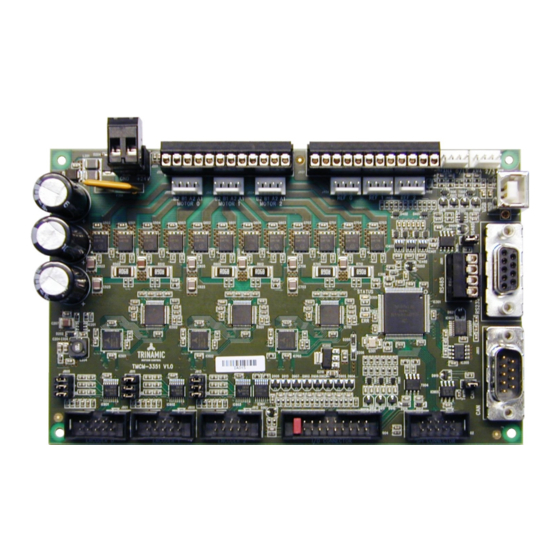
The TMCM-3351 is a three axes motor controller/driver board for 2-phase bipolar stepper motors. It
is the direct successor of the TMCM-351 - mechanically and electrically compatible - with our latest
generation of stepper driver and motion controller ICs supporting linear and S-shaped ramps and
closed-loop operation with external ABN-encoders.
Applications
• Laboratory Automation
• Manufacturing
• Semiconductor Handling
Simpli ed Block Diagram
©2021 TRINAMIC Motion Control GmbH & Co. KG, Hamburg, Germany
Terms of delivery and rights to technical change reserved.
Download newest version at:
www.trinamic.com
Read entire documentation.
• Robotics
• Factory Automation
• Test & Measurement
Features
• 3-axes controller/driver for 2-phase
bipolar stepper motor
• Linear and S-shaped ramps and closed-
loop operation with external encoder
• +11. . . 28V DC supply voltage
• Up to 3A RMS motor current
• RS485, CAN, RS232 & USB interfaces
• multi-purpose inputs and outputs
• Life Science
• Biotechnology
• Liquid Handling
MODULE
Advertisement
Table of Contents

Subscribe to Our Youtube Channel
Related Manuals for Trinamic TMCM-3351


Summary of Contents for Trinamic TMCM-3351
- Page 1 Hardware Version V1.00 | Document Revision V1.00 • 2017-SEP-01 The TMCM-3351 is a three axes motor controller/driver board for 2-phase bipolar stepper motors. It is the direct successor of the TMCM-351 - mechanically and electrically compatible - with our latest generation of stepper driver and motion controller ICs supporting linear and S-shaped ramps and closed-loop operation with external ABN-encoders.
-
Page 2: Table Of Contents
TMCM-3351 Hardware Manual • Hardware Version V1.00 | Document Revision V1.00 • 2017-SEP-01 2 / 31 Contents 1 Features 2 Order Codes 3 Mechanical and Electrical Interfacing 3.1 Size of the Board .......... - Page 3 TMCM-3351 Hardware Manual • Hardware Version V1.00 | Document Revision V1.00 • 2017-SEP-01 3 / 31 15.2 Document Revision ..........31 ©2021 TRINAMIC Motion Control GmbH &...
-
Page 4: Features
Linear ramps and S-shaped ramps as well as closed-loop operation with optional encoders are supported for each of the three axes. The TMCM-3351 offers a large number of general purpose digital and analog inputs and digital outputs. For communication a number of serial communication interfaces including RS485, CAN, USB and RS232 are available. -
Page 5: Order Codes
TMCM-3351 Hardware Manual • Hardware Version V1.00 | Document Revision V1.00 • 2017-SEP-01 5 / 31 2 Order Codes The TMCM-3351 is available with standard TMCL rmware or CANopen rmware. TMCM-3351 Order Codes Order Code Description Size (LxWxH) TMCM-3351 3-axes stepper controller / driver, +24V, 3x... -
Page 6: Mechanical And Electrical Interfacing
3.1 Size of the Board The TMCM-3351 three axes controller / driver board has a board size of 160mm x 100mm (standard euro board format). Four mounting holes are available for standard M3 screws - one in each corner. All four mounting holes are non-plated and isolated. -
Page 7: Connectors
TMCM-3351 Hardware Manual • Hardware Version V1.00 | Document Revision V1.00 • 2017-SEP-01 7 / 31 4 Connectors The TMCM-3351 offers connectors for three stepper motors, related reference switches, related encoders (optional for closed-loop operation), a number of analog and digital inputs and outputs and several serial interfaces (RS485, CAN, USB and RS232). - Page 8 TMCM-3351 Hardware Manual • Hardware Version V1.00 | Document Revision V1.00 • 2017-SEP-01 8 / 31 Connector Connector type on-board Mating connector type Reference RIA 183-12, 12 pins, 3.5mm pitch 1x RIA 169-12 (12 pins) or e.g. 3x RIA 169-04 (4 pins, one connector for each motor), screw type terminal block, plug- gable, 3.5mm pitch...
-
Page 9: Power Connector
TMCM-3351 Hardware Manual • Hardware Version V1.00 | Document Revision V1.00 • 2017-SEP-01 9 / 31 4.1 Power Connector A 2 pin, detachable screw connector is used for power supply input. All additional voltages required by the TMCM-3351 are generated on-board from this supply input. -
Page 10: End Switch Connector
TMCM-3351 Hardware Manual • Hardware Version V1.00 | Document Revision V1.00 • 2017-SEP-01 10 / 31 Motor Connector (Crimp Style Connector) Label Description Motor_0/1/2_B- Motor 0/1/2 coil B Motor_0/1/2_B+ Motor 0/1/2 coil B Motor_0/1/2_A- Motor 0/1/2 coil A Motor_0/1/2_A+ Motor 0/1/2 coil A Table 5: Motor Connector (Crimp Style Connector) 4.3 End Switch Connector... -
Page 11: Analog Input Connector
Table 7: End Switch Connector (Crimp Style Connector) 4.4 Analog Input Connector The TMCM-3351 offers four dedicated analog inputs with programmable range (0. . . +3.3V or 0. . . +10V). There are two 4-pin connectors (Molex KK series) with two analog inputs available via each connector. -
Page 12: Rs232 Connector
For communication via RS232 transmit serial data of the TMCM-3351 has to be connected to RS232 receive serial data of the host / master and RS232 receive data of the TMCM-3351 to transmit data of the host / master - requiring a cross-connection / -cable. -
Page 13: Spi Connector
RS485 bus should be terminated at both ends of the bus. For any intermediate nodes / bus connections please remove line termination jumper (see 5, also). In contrast to the TMCM-351 the TMCM-3351 does not require any jumper setting / selection in order to enable RS485 connection. RS485 communication is available after power-up (power supply input) without any further con guration. -
Page 14: Encoder Connector
TMCM-3351 Hardware Manual • Hardware Version V1.00 | Document Revision V1.00 • 2017-SEP-01 14 / 31 Label Label OUT_6 OUT_7 +5V_output IN_0 IN_1 IN_2 IN_3 IN_4 IN_5 IN_6 IN_7 /Shutdown Table 14: I/O Connector The /Shutdown input pin has to be connected to the supply voltage in order to enable the driver stages for all three stepper motor axes. -
Page 15: Jumper Settings
TMCM-3351 Hardware Manual • Hardware Version V1.00 | Document Revision V1.00 • 2017-SEP-01 15 / 31 5 Jumper Settings Most settings for the TMCM-3351 are done through software. Nevertheless, a few jumpers are available for con guration. Termination RS485 Termination... -
Page 16: Encoder Input Termination
TMCM-3351 Hardware Manual • Hardware Version V1.00 | Document Revision V1.00 • 2017-SEP-01 16 / 31 Jumper Description Termination Encoder 2 Termination for encoder line receiver input 2. Encoder input 2 is related to motor axis 0. For differential encoder signals –... -
Page 17: Leds
TMCM-3351 Hardware Manual • Hardware Version V1.00 | Document Revision V1.00 • 2017-SEP-01 17 / 31 6 LEDs Both on-board LEDs (one green and one red) are connected directly to the on-board microcontroller. Therefore, function of the LEDs is depending on rmware. -
Page 18: Communication
18 / 31 7 Communication 7.1 RS485 For remote control and communication with a host system the TMCM-3351 provides a two wire RS485 bus interface. For proper operation the following items should be taken into account when setting up an RS485 network: 1. -
Page 19: Usb
Figure 8: RS485 bus lines with resistor network 7.2 USB For remote control and communication with a host system the TMCM-3351 provides a USB 2.0 full-speed (12Mbit/s) interface (USB Type B connector). As soon as a USB-Host is connected the module will accept commands via USB. - Page 20 TMCM-3351 Hardware Manual • Hardware Version V1.00 | Document Revision V1.00 • 2017-SEP-01 20 / 31 speeds, the bus should be properly terminated at both ends. The TMCM-3351 does not integrate any termination resistor. Termination resistor (120 Ohm) maybe added externally at both ends of the bus or the on-board termination maybe activated by adding a jumper (see 5).
-
Page 21: Motor Driver Current
TMCM-3351 Hardware Manual • Hardware Version V1.00 | Document Revision V1.00 • 2017-SEP-01 21 / 31 8 Motor Driver Current The on-board stepper motor driver operates current controlled. The driver current may be programmed in software with 32 effective current scaling steps (CS) in hardware. - Page 22 TMCM-3351 Hardware Manual • Hardware Version V1.00 | Document Revision V1.00 • 2017-SEP-01 22 / 31 Motor current Current scaling Motor current Motor current setting in soft- step in hardware PEAK ware (TMCL) (CS) 136..143 2.688 1.901 144..151 2.838 2.007 152..159...
-
Page 23: Functional Description
23 / 31 9 Functional Description The TMCM-3351 is a highly integrated 3-axes controller/driver module for stepper motors. It offers sepa- rate motion controllers in hardware for all three axes supporting linear and S-shaped ramps, open-loop operation and closed-loop operation with external encoder. The TMCM-3351 can be controlled via one out of four available serial interfaces RS485, CAN, RS232 or USB. -
Page 24: Operational Ratings And Characteristics
TMCM-3351 Hardware Manual • Hardware Version V1.00 | Document Revision V1.00 • 2017-SEP-01 24 / 31 10 Operational Ratings and Characteristics Never exceed the absolute maximum ratings! Keep the power supply voltage NOTICE below the upper limit of +30V! Otherwise the board electronics will seriously be damaged! Especially, when the selected operating voltage is near the upper limit a regulated power supply is highly recommended. - Page 25 TMCM-3351 Hardware Manual • Hardware Version V1.00 | Document Revision V1.00 • 2017-SEP-01 25 / 31 Operational Ratings of the RS485 Interface Symbol Parameter Unit Number of nodes connected to single RS485 network RS485 Maximum bit rate supported on RS485 network...
-
Page 26: Abbreviations Used In This Manual
TMCM-3351 Hardware Manual • Hardware Version V1.00 | Document Revision V1.00 • 2017-SEP-01 26 / 31 11 Abbreviations used in this Manual Abbreviation Description Integrated Development Environment Light Emmitting Diode Root Mean Square value TMCL TRINAMIC Motion Control Language Table 24: Abbreviations used in this Manual ©2021 TRINAMIC Motion Control GmbH &... -
Page 27: Figures Index
TMCM-3351 Hardware Manual • Hardware Version V1.00 | Document Revision V1.00 • 2017-SEP-01 27 / 31 12 Figures Index Board Dimensions and Positions of RS485 bus structure with termination Mounting Holes (all Values in mm) resistors .... -
Page 28: Tables Index
TMCM-3351 Hardware Manual • Hardware Version V1.00 | Document Revision V1.00 • 2017-SEP-01 28 / 31 13 Tables Index TMCM-3351 Order Codes ..I/O Connector .... -
Page 29: Supplemental Directives
14.5 Disclaimer: Life Support Systems TRINAMIC Motion Control GmbH & Co. KG does not authorize or warrant any of its products for use in life support systems, without the speci c written consent of TRINAMIC Motion Control GmbH & Co. KG. -
Page 30: Collateral Documents & Tools
In particular, this also applies to the stated possible applications or areas of applications of the product. TRINAMIC products are not designed for and must not be used in connection with any applications where the failure of such products would reasonably be expected to result in signi cant personal injury or death (safety-Critical Applications) without TRINAMIC’s speci c written consent. -
Page 31: Revision History
TMCM-3351 Hardware Manual • Hardware Version V1.00 | Document Revision V1.00 • 2017-SEP-01 31 / 31 15 Revision History 15.1 Hardware Revision Version Date Author Description V1.0 2017-MAY-04 First prototypes Table 25: Hardware Revision 15.2 Document Revision Version Date Author Description 0.90...
Need help?
Do you have a question about the TMCM-3351 and is the answer not in the manual?
Questions and answers