Table of Contents
Advertisement
Quick Links
Introduction
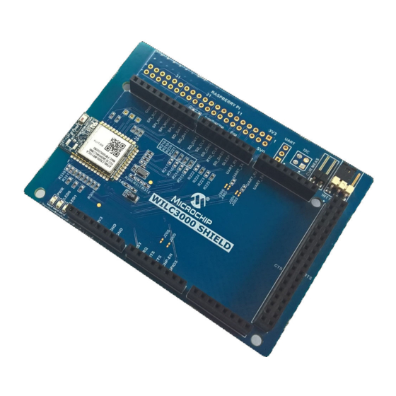
The ATWILC3000 Shield is an interface board designed to demonstrate the ATWILC3000-MR110CA, a
®
single chip IEEE
802.11 b/g/n RF/Baseband/MAC network controller with Bluetooth
module is optimized for low-power applications. The ATWILC3000 module can be connected to the host
MCU board using any of the following interfaces:
®
•
For Wi-Fi
, either Secure Digital Input/Outputs (SDIO) or Serial Peripheral Interface (SPI) is used.
•
For Bluetooth, Universal Asynchronous Receiver/Transmitter (UART) is used.
Figure 1. ATWILC3000 Shield Board
Features
2
•
Debug I
C and UART Header Footprints
•
External Power Supply Header
•
Current Measurement Header
•
Power and User LED
•
Chip Antenna
•
Supports 32.768 kHz Low-Power Surface Mount Device (SMD) Crystal Oscillator
•
Arduino Shield Stacking Connector
–
Supports Wi-Fi through SDIO by default. Pinout is compatible with ATSAMA5D4-XULT
©
2018 Microchip Technology Inc.
ATWILC3000 Shield User Guide
ATWILC3000
User Guide
®
Low Energy. This
DS50002769A-page 1
Advertisement
Table of Contents

Related Manuals for Microchip Technology ATWILC3000 Shield


Summary of Contents for Microchip Technology ATWILC3000 Shield
-
Page 1: Introduction
ATWILC3000 ATWILC3000 Shield User Guide Introduction The ATWILC3000 Shield is an interface board designed to demonstrate the ATWILC3000-MR110CA, a ® ® single chip IEEE 802.11 b/g/n RF/Baseband/MAC network controller with Bluetooth Low Energy. This module is optimized for low-power applications. The ATWILC3000 module can be connected to the host MCU board using any of the following interfaces: ®... - Page 2 Supports Wi-Fi through SPI (optional). Pinout is compatible with Arduino header specification – Supports Bluetooth through UART • Raspberry Pi Stacking Connector – Supports Wi-Fi through SDIO or SPI – Supports Bluetooth through UART User Guide DS50002769A-page 2 © 2018 Microchip Technology Inc.
-
Page 3: Table Of Contents
Features.......................... 1 1. Kit Overview......................4 2. ATWILC3000 Shield Peripheral Configuration............5 3. Design Documentation and Relevant Links...............6 4. Hardware Specifications....................7 4.1. ATWILC3000 Shield Arduino Shield Stacking Connectors............7 4.2. ATWILC3000 Shield Raspberry Pi Stacking Connector...............9 4.3. Power Supply Connector......................11 4.4. -
Page 4: Kit Overview
Kit Overview The ATWILC3000 Shield is a shield board containing the low-power ATWILC3000-MR110CA 802.11 b/g/n IoT module. By default, the ATWILC3000 Shield is configured to use with the SDIO interface which is compatible with SAMA5D4-XULT. Figure 1-1. ATWILC3000 Shield Evaluation Kit Overview... -
Page 5: Atwilc3000 Shield Peripheral Configuration
The ATWILC3000 module on the shield board can communicate with the host board using either SDIO or SPI. By default, SDIO is supported. A resistor combination must be modified to add SPI support. The following table provides resistor configuration details. Table 2-1. ATWILC3000 Shield Resistor Configuration for SDIO/SPI Peripheral Interface Required Modification for Resistors SDIO... -
Page 6: Design Documentation And Relevant Links
ATWILC3000. ® ® • SMART SAMA5 ARM Cortex based MPUs page is an online directory to access the tools and software for SAMA5 Cortex-A5-Based Embedded MPUs. User Guide DS50002769A-page 6 © 2018 Microchip Technology Inc. -
Page 7: Hardware Specifications
ATWILC3000 Shield Arduino Shield Stacking Connectors The ATWILC3000 Shield contains Arduino shield stacking connectors, which are used to connect the board to an MCU base board. This is also used to expose the unused pins to the user. The pinout definition for the shield connectors are given in the following tables. - Page 8 GPIO signal Not connected Not connected Table 4-5. J204 Stacking Connector Pin Number Function Description ® UART_RX_1 Bluetooth UART receive ® UART_TX_1 Bluetooth UART transmit Not connected Not connected Not connected Not connected User Guide DS50002769A-page 8 © 2018 Microchip Technology Inc.
-
Page 9: Atwilc3000 Shield Raspberry Pi Stacking Connector
ATWILC3000 Shield Raspberry Pi Stacking Connector The ATWILC3000 Shield contains a Raspberry Pi compatible 40-pin stacking connector used to connect the board to a Raspberry Pi base board. This is also used for exposing the unused pins to the user. The pinout definition for the Raspberry Pi connector is given in the following table. - Page 10 UART receive output. By default, this pin is not connected. Short J208 to connect. SDDATA2 SDIO Data 2. By default, this pin is not connected. Mount R231 (0Ω) to connect. Not connected User Guide DS50002769A-page 10 © 2018 Microchip Technology Inc.
-
Page 11: Power Supply Connector
Not connected Power Supply Connector The ATWILC3000 Shield is powered either from the shield connector or from an external power supply. The header (J300) is used to switch between 3.3V supply from the shield connector or a 3.3V external power supply. The following tables provide pin details and the connector configuration of the power supply connector. - Page 12 ATWILC3000 Hardware Specifications Table 4-11. Wi-Fi UART Connector Pin on Extension Port Pin on ATWILC3000 Module Function UART Receiver UART Transmitter Ground User Guide DS50002769A-page 12 © 2018 Microchip Technology Inc.
-
Page 13: Ce And Fcc
The frequency and magnitude of the emissions are determined by several factors, including layout and routing of the target application, where the product is used. User Guide DS50002769A-page 13 © 2018 Microchip Technology Inc. -
Page 14: Hardware Revision History And Known Issues
Identifying Product ID and Revision The revision and product identifier of the ATWILC3000 Shield is available on the sticker on the bottom side of the PCB. The identifier and revision are printed in plain text as A09-nnnn\rr, where nnnn is the identifier and rr is the revision. -
Page 15: Document Revision History
Updated the document from Atmel to Microchip template • Assigned a new Microchip document number Previously Released Atmel Revisions Doc. Rev. Date Comment 42731B 04/2017 Added section regulatory notice with Argentina certification information 42731A 05/2016 Initial document release User Guide DS50002769A-page 15 © 2018 Microchip Technology Inc. -
Page 16: The Microchip Web Site
Microchip’s Data Sheets. Most likely, the person doing so is engaged in theft of intellectual property. • Microchip is willing to work with the customer who is concerned about the integrity of their code. User Guide DS50002769A-page 16 © 2018 Microchip Technology Inc. -
Page 17: Legal Notice
SQTP is a service mark of Microchip Technology Incorporated in the U.S.A. Silicon Storage Technology is a registered trademark of Microchip Technology Inc. in other countries. GestIC is a registered trademark of Microchip Technology Germany II GmbH & Co. KG, a subsidiary of Microchip Technology Inc., in other countries. -
Page 18: Quality Management System Certified By Dnv
ATWILC3000 © 2018, Microchip Technology Incorporated, Printed in the U.S.A., All Rights Reserved. ISBN: 978-1-5224-3263-0 Quality Management System Certified by DNV ISO/TS 16949 Microchip received ISO/TS-16949:2009 certification for its worldwide headquarters, design and wafer fabrication facilities in Chandler and Tempe, Arizona; Gresham, Oregon and design centers in California ®... -
Page 19: Worldwide Sales And Service
New York, NY Sweden - Stockholm Tel: 631-435-6000 Tel: 46-8-5090-4654 San Jose, CA UK - Wokingham Tel: 408-735-9110 Tel: 44-118-921-5800 Tel: 408-436-4270 Fax: 44-118-921-5820 Canada - Toronto Tel: 905-695-1980 Fax: 905-695-2078 User Guide DS50002769A-page 19 © 2018 Microchip Technology Inc.
Need help?
Do you have a question about the ATWILC3000 Shield and is the answer not in the manual?
Questions and answers