Table of Contents
Advertisement
Advertisement
Chapters
Table of Contents

Related Manuals for Acer Chromebook C732


Summary of Contents for Acer Chromebook C732
- Page 1 Acer Chromebook C732 / C732T / C732L / C732LT SERVICE GUIDE...
- Page 2 Copyright Copyright © 2018 by Acer Incorporated. All rights reserved. No part of this publication may be reproduced, transmitted, transcribed, stored in a retrieval system, or translated into any language or computer language, in any form or by any means, electronic, mechanical, magnetic, optical, chemical, manual or otherwise, without the prior written permission of Acer Incorporated.
- Page 3 Conventions The following conventions are used in this manual: WARNING: Indicates a potential for personal injury. CAUTION: Indicates a potential loss of data or damage to equipment. IMPORTANT: Indicates information that is important to know for the proper completion of a procedure, choice of an option, or completing a task. The following typographical conventions are used in this document: Book titles, directory names, file names, path names, and program/process names ...
- Page 4 Acer-authorized Service Providers: The Acer office may have a different part number code than those given in the FRU list in this service guide. A list must be provided by the regional Acer office to order FRU parts for repair and service of customer machines.
-
Page 5: Table Of Contents
CHAPTER 1 Hardware Specifications Features ..........1-5 Operating System . - Page 6 AC Adapter ........1-25 DVD Super-Multi Drive (N/A) .
- Page 7 CHAPTER 3 Machine Maintenance Procedures Introduction ......... 3-5 General Information .
- Page 8 Replacing the LCD Panel ......3-51 Replacing the Microphone Board ..... 3-53 Replacing the Camera Module .
- Page 9 Model Definition and Configuration Chromebook C732 ........7-3 Chromebook C732T .
- Page 11 CHAPTER Hardware Specifications...
- Page 12 Features ..........1-5 Operating System .
- Page 13 WWAN Module (3G/LTE) (For C732L & C732LT only) ..1-31 Card Reader ........1-31 Audio Interface.
-
Page 15: Features
HD Graphics 500, supporting OpenGL 4.3, OpenCL™ 1.2 and Microsoft ® DirectX Display For Chromebook C732 & C732L: 11.6" HD 1366 x 768 resolution (220-nit), high-brightness Acer ComfyView™ LED-backlit TFT LCD 16:9 aspect ratio Ultra slim design ... -
Page 16: Audio
Two 2W built-in stereo speakers Built-in microphone Storage Embedded MultiMedia Card (eMMC): For Chromebook C732 & C732T: 16 / 32 / 64GB For Chromebook C732T & C732LT: 32 / 64GB Card reader: Supports MicroSD / MicroSDHC / Micro SDXC ... -
Page 17: Privacy Control
Kensington lock slot Color Options For Chromebook C732T: Black-Steel gray For Chromebook C732, C732L & C732LT: Black Dimension and Weight Dimensions: 302 (W) x 209 (D) x 21.3 (H) mm (11.89 x 8.23 x 0.84 inches) ... -
Page 18: Input And Control
Input and Control Keyboard: 74-/75-/78-key Acer FineTip keyboard with international language support TouchPad: Fully clickable touchpad featuring click-anywhere functionality: one-finger touch to left-click; two-finger touch to right-click; two-finger scrolling Input and Output (I/O) Ports For Chromebook C732 & C732T: Two USB Type-C™... -
Page 19: System Compliance
System Compliance ® ENERGY STAR Warranty One-year International Travelers Warranty (ITW) Hardware Specifications and Configurations... -
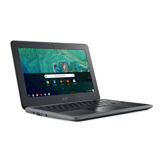
Page 20: Notebook Tour
Notebook Tour Figure 1-1. Opened Front View Table 1-1. Opened Front View Icon Item Description Microphone Internal microphone for sound recording. Camera Status LED Indicates the camera activity (Green). Also called Liquid-Crystal Display (LCD), displays computer output (configuration may vary by Display Screen model), and supports multi-touch functionality (for touchscreen model only). - Page 21 Figure 1-2. Right View (For Chromebook C732 & C732T) Table 1-2. Right View (For Chromebook C732 & C732T) Icon Item Description Connects to USB 2.0 or 3.0 devices (e.g., USB USB 3.0 Port mouse, USB camera). Connects a USB Type-C™ AC adapter to supply ...
- Page 22 Figure 1-3. Right View (For Chromebook C732L & C732LT) Table 1-3. Right View (For Chromebook C732L & C732LT) Icon Item Description Insert a Micro-SIM card to connect to a mobile USIM Card Slot broadband network. CARD Connects a USB Type-C™ AC adapter to supply ...
- Page 23 Figure 1-4. Left View Table 1-4. Left View Icon Item Description Indicates the computer's battery status. Green On: The battery is fully charged (with AC power connected). Orange On: The battery is charging or the Battery Indicator system is running on a battery without AC power connected).
- Page 24 Table 1-4. Left View Icon Item Description Accepts microSD cards. NOTE: MicroSD Card Reader Push to remove/install the card. Only one card can operate at any given time. Connects to audio line-out devices and accepts Microphone / input from external microphone (3.5 mm Headphone Jack Standard TRRS / OMTP TRRS Type) NOTE:...
- Page 25 Figure 1-5. Top View Hardware Specifications and Configurations 1-15...
- Page 26 Figure 1-6. Base View Table 1-5. Base View Icon Item Description Liquid spilled on the keyboard can drain out of the holes in the underside of the housing. IMPORTANT: Drain Holes To prevent the accumulation of liquid inside the keyboard, make sure you do not block the drain holes.
-
Page 27: Touchpad Basics
TouchPad Basics Figure 1-7. TouchPad Move your finger across the TouchPad (1) to move the cursor. Click on the left (2) and right (3) button zone located beneath the TouchPad to perform selection and execution functions. These two buttons are the equivalent of the left and right buttons on a mouse. -
Page 28: Using The Keyboard
Using the Keyboard The computer has a close-to-full-sized keyboard and separate cursor, function and special keys. Hotkeys The computer employs hotkeys or key combinations to access most of the computer's controls like screen brightness and volume output. Figure 1-8. Keyboard Function Keys Hot key Function Description... -
Page 29: System Block Diagram
System Block Diagram Figure 1-9. System Block Diagram NOTE: NOTE: Only on-board eMMC models Hardware Specifications and Configurations 1-19... -
Page 30: Specification Tables
Specification Tables Computer Specifications Item Metric Imperial Dimensions Width 302 mm 11.89 in. Depth 209 mm 8.23 in. Height (front to rear) 21.3 mm 0.84 in. Weight (equipped with battery) 1.26 kg 2.78 lbs Input Power Operating Voltage 5 / 9 / 15 / 20 V Operating Current 3 A (45 W) Temperature... -
Page 31: System Board Major Chips
System Board Major Chips Item Specification ® ® Core Logic Intel Celeron N3350 ® ® Intel Celeron N3450 ® Intel HD Graphics 500 Integrated in PCH USB Type-C™ 3.1 port x1 USB 3.0 port x2 (for C732 & C732T) ... -
Page 32: Processor
Processor Item Specification Architecture ® Intel Apollo Lake SoC Package Type FCBGA1296 (31 x 24 mm Core Logic Quad/Dual IA processor core: 2 modules of 2 cores each for Quad Core, supporting Out of Order Execution (OOE) 2 modules, 2 cores grouped per module (Dual-Core Module) ... -
Page 33: Bios (Not Available In This Model)
Item Specification DIMM Type SDRAM memory interface DIMM Speed 1600 / 2133 / 2400 MT/s soDIMM DIMM Package 200-ball FBGA BIOS (not available in this model) Item Specification BIOS vendor BIOS version BIOS ROM type BIOS ROM size Features Keyboard Item Specification Type... -
Page 34: Usb Type-C Port
USB Type-C Port Item Specification USB Compliance Level USB 3.1 Gen 1 compliant (speed up to 5 Gb/s) Output Current of Power 5 / 9 / 15 / 20V; 3.0 A max. Power-off USB Charging Mode DisplayPort Version DisplayPort 1.2 Thunderbolt Version not supported Power Delivery for Charging... -
Page 35: Ac Adapter
AC Adapter Item Specification Vendor Chicony LITE-ON Model A16-045N1A (A045R053L) PA-1450-78AP Normal Input 100-240 Vac, 50-60 Hz 115-230 Vac, 50-60 Hz Voltage (The adapter should operate (The adapter should operate from 90-264 Vac with an input from 90-264 Vac with an input frequency from 47-63 Hz.) frequency from 47-63 Hz.) Input Current... -
Page 36: Hard Disk Drive (Avl Components) (N/A)
Hard Disk Drive (AVL components) (N/A) Item Specification Vendor & Model Name Capacity (GB) Bytes per sector Data heads Drive Format Disks Spindle speed (RPM) Performance Specifications Buffer size (Mbytes) Interface Fast data transfer rate (Gbits / sec, max) Media data transfer rate (Mbytes/sec max) DC Power Requirements Voltage tolerance... -
Page 37: Embedded Multimedia Card (Emmc)
Embedded MultiMedia Card (eMMC) Item Specification Vendor & Model HYNIX HYNIX HYNIX H26M52208FPR H26M64208EMR H26M78208CMR H26M62002JPR SANDISK SanDisk SDINADF4-16G-1220 SDINADF4-32G-1220 Capacity (GB) (for C732 & C732T only) Features Packaged NAND flash memory with eMMC™ 5.1 interface eMMC™ 5.1 compatible (backward compatible to eMMC™ 5.0 & ... -
Page 38: Touchscreen Lcd (For C732T & C732Lt Only)
11.6” Touchscreen LCD (for C732T & C732LT only) Item Specification Vendor & Model name B116XAK01.0 Screen Diagonal (mm) 294.09 (11.58W”) Active Area (mm) 256.125 (H) x 144 (V) Display Resolution (pixels) 1366 x 3 (RGB) x 768 Pixel Pitch (mm) 0.1875 x 0.1875 200 min. -
Page 39: Video Interface
Video Interface Item Specification Architecture ® Integrated Intel Apollo Lake Architecture (IA) SoC Package Built-in to the CPU Interface Built-in to the CPU Compatibility Hardware accelerated video decode/encode support for HEVC (H.265), H.264, MVC, VP8, VP9, MPEG2, VC-1, WMV9, JPEG/MJPEG formats Supports Intel®... -
Page 40: Wireless + Bluetooth Module (A/B/G/N/Ac)
Wireless + Bluetooth Module (a/b/g/n/ac) Item Specifications Vendor & Model Liteon WCBN807 A-AA Intel® Dual-Band Qualcomm Atheros Wireless-AC 7265 (Stone NFA344A 2x2 Wi-Fi+ BT 4.1 Peak 2) 2x2 AC + BT 4.0 Chipset Qualcomm Atheros VHT-5G Wi-Fi 2x2 and QCA6174A Bluetooth combination single-chip Form Factor... -
Page 41: Wwan Module (3G/Lte) (For C732L & C732Lt Only)
WWAN Module (3G/LTE) (For C732L & C732LT only) Item Specifications Vendor & Model Fibocom L850-GL Form Factor PCIe M.2 Operating Band LTE FDD: Band 1, 2, 3, 4, 5, 7, 8, 11, 12, 13, 17, 18, 19, 20, 21, 26, 28, 29, 30, 66 LTE TDD: Band 38, 39, 40, 41 ... -
Page 42: Audio Interface
Audio Interface Item Specification Audio Controller DIalog Semiconductor DA7219 Audio onboard or optional On board Mono or Stereo Mono microphone to ADC path, and stereo DAC to HP path Sampling Rate 8 kHz to 96 kHz, depending on the required input sample ... -
Page 43: Camera
Camera Item Specification Vendor & Model name LITE-ON Chicony 4SF109N2E CNFEH46-1 Lens Type AOET 1LS1085F AOET 1LS1085C Sensor Type Hynix 165 CMOS sensor OV9728 CMOS sensor Pixel Resolution 1280 x 720 (1M) (HD) Focus Area 22 cm ~ infinity 15.5 cm ~ infinity focus on 50 cm focus on 50 cm Focus Mode... -
Page 44: System Led Indicator
Item Specification Suspend to RAM (Standby) S3 is a suspend state in which the core power planes of the (G1/S3) processor are turned off and the suspend wells remain powered. VGA Suspend PCMCIA Suspend Audio Power Down Hard Disk Power Down ... -
Page 45: System Utilities
CHAPTER System Utilities... - Page 46 Introduction ......... 2-3 Key Component Replacement and HWID Re-configuration .
-
Page 47: Introduction
System Utilities Introduction This chapter contains information on how to re-configure the Acer hromebook C732 / C732T / C732L / C732LT HWID as well as test procedures for your notebook’s various components. Key Component Replacement and HWID Re-configuration When certain key components are replaced, the correct hardware ID (HWID) must be... - Page 48 UseWin32DiskImager.exe tool to create a RMA install shim Fail If always fail Switch DEV mode Please try to re-copy The RMA.bin Install image from install shim to chrome book PASS Verify HW Change to release image Figure 2-1. HWID Re-Configuration Flow Chart System Utilities...
-
Page 49: Creating Rma Shim Using "Win32Diskimager" In Windows2-5
Creating RMA Shim Using “Win32DiskImager” in Windows 1. In another notebook or PC running Windows, create a new folder named RMA Shim Pienza_Astronaut_ZAL_RMA_Shim_R65_20180330.bin and copy file and the Win32DiskImager tool folder to the RMA shim folder. Figure 2-2. Win32DiskImager Tool 2. - Page 50 4. Select the drive name assigned to the USB2.0 drive label (example here is E:\), and then click the folder icon. Figure 2-5. Win32 Disk Imager Drive & Folder Selection 5. The Select a disk image window appears. Select in the Save as type field to show all file types.
- Page 51 6. After saving the image file, the system wll go back to the Win32 Disk Imager window, click Write. NOTE: NOTE: DO NOT click the ”Read” button. Figure 2-7. Choosing Write 7. Click Yes to confirm your decision. Figure 2-8. Confirming the decision 8.
- Page 52 9. Once the program has successfully written the image, the system shows Write Succssful message. Click OK, and then remove the USB drive from the notebook or PC running Windows. Figure 2-10. Write Successful System Utilities...
-
Page 53: Switching To Developer Mode (Dev Mode)
Switching to Developer Mode (DEV Mode) 1. Plug in the AC adapter then open the lid (LCD panel) to turn on the system. NOTE: NOTE: DO NOT unplug the AC adapter. Esc + Reload + Power 2. Press the keys simultaneously and hold the three keys for more than one second to enter Recovery Mode (Figure 2-11). - Page 54 5. The system will clean the data and switch to Developer Mode. Wait 30 seconds, then the system will proceed to the next step automatically. Figure 2-14. Transitioning to Developer Mode Screen 6. A message will appear to indicate that the system is transitioning to Developer Mode.
-
Page 55: Install Rma Shim
Install RMA Shim 1. Unplug the AC adapter and remove all cables from the system. 2. Place the system on a flat surface, the bottom side is up. 3. Remove twelve (12) screws from the base cover (Figure 2-17). Figure 2-17. Base Cover Removal 4. - Page 56 5. Then, pry apart the base cover from the recess on the right LCD hinge (Figure 2-19). Figure 2-19. Base Cover Removal 6. Continue along the edges of the base cover until all the latches have been released. 7. Remove the base cover (Figure 2-20).
- Page 57 8. Peel off and remove the tape (A) on the battery connector (Figure 2-21). Figure 2-21. Disconnecting the Battery Cable 9. Disconnect the battery cable from the mainboard connector (B) (Figure 2-22). Figure 2-22. Disconnecting the Battery Cable System Utilities 2-13...
- Page 58 10. Carefully place the base cover onto the top assembly. Make sure that the edges of the base cover are aligned properly to those of the top assembly. 11. Press downward on the system to engage the tabs. Make sure all the tabs are fully engaged (Figure 2-23).
- Page 59 14. Once inserting the recovery USB stick or SD card, the RMA image installation will start. Wait for about few minutes for this process to complete. Figure 2-26. Copying the RMA image Enter 15. When this image appears, type and click to begin installing the RMA shim.
- Page 60 16. System will display the RMA shim installation process as shown in Figure 2-28. Figure 2-28. Installation Process 17. The system will restart when the RMA image installation is complete. Meanwhile, unplug the recovery USB stick or SD card and AC adapter from the system. 18.
- Page 61 19. Connect the battery cable to the mainboard connector (B) (Figure 2-30). 20. Attach and secure the tape (A) to the battery connector (Figure 2-30). Figure 2-30. Connecting the Battery Cable 1. Carefully place the base cover onto the top assembly. Make sure that the edges of the base cover are aligned properly to those of the top assembly.
- Page 62 3. Install and secure twelve (12) screws to the base cover (Figure 2-32). Figure 2-32. Base Cover Screw Location 2-18 System Utilities...
-
Page 63: Run Rma Shim
Run RMA Shim 1. Plug in the AC adapter then open the lid (LCD panel) to turn on the system. NOTE: NOTE: DO NOT unplug the AC adapter. 2. The system will restart automatically when the RMA image installation is complete and then automatically boot to Factory Test mode (This process may take about 30-60 seconds). -
Page 64: Start The Fatp Test
Start the FATP Test Ctrl + Alt + 0 1. Press simultaneously to start the FATP test. Figure 2-35. FATP Tests cros 2. Type in the Password field and click OK to begin the test. Figure 2-36. FATP Tests 3. Select CrOS Factory > Switch test list > Main Test List for RMA FATP in the Factory test menu. - Page 65 4. Confirm your decision in the pop-up window. The FATP tests will start. Figure 2-38. FATP Tests SPACE 5. Press key to start the test procedures. The system will begin testing various components. Follow the instructions on the screen and complete the actions described in the next section to finish each test.
-
Page 66: Run The Fatp Test
Run the FATP Test Lid Switch Test 1. Close the lid (LCD cover) of the system. 2. Open the lid (LCD cover) when you hear the “OK” voice prompt from the system. Figure 2-40. Lid Switch Test Display Point Space 1. - Page 67 Space 2. Check if there is any black point shown. Press to return to the window. Figure 2-42. Display Point Test Enter 3. Enter the number of black points found and press to continue to the white point check. Space 4.
- Page 68 Display Test Space 1. Press to test the color listed in the display test. Figure 2-44. Display Test Enter 2. Press to pass if the color displayed on the screen matches the color listed in the display test. Figure 2-45. Display Test 3.
- Page 69 Camera Test: Face Detection Enter 1. Press to pass if the image from the main camera appears on screen, or press to try it again. Figure 2-46. Camera Test LED Test 1. Press the corresponding number when the LED lights up the same color: a.
- Page 70 SD Performance Test 1. Insert an microSD card into the microSD Card Slot. Figure 2-48. MicroSD Card Slot CAUTION: Any data in the inserted microSD card reader will be cleared during the SD Performance test. Ensure that you either use an empty microSD card or back up all the data located on the card before you proceed with the SD card test.
- Page 71 Cellular Test The system will run an auto-test. SIM Test (For C732L & C732LT only) 1. Insert an USIM card into the USIM card slot. Figure 2-51. USIM Card Slot Space 2. Press to continue the SIM test. Figure 2-52. SIM Test 3.
- Page 72 LTE RSSI Test The system will run an auto-test. Bluetooth Test 1. Turn on a Bluetooth device and enable Bluetooth on the system. Place the device near the system. Enter to run an auto-test. 2. Press Figure 2-54. Bluetooth Test Wi-Fi Test The system will run an auto-test.
- Page 73 Touchpad Test Follow the steps below to start the touchpad tests: Space 1. Take off your fingers from the touchpad and press to start the tests. Figure 2-56. Touchpad Test 2. Place one finger on the touchpad and move the finger throughout the touchpad area (Test B).
- Page 74 Keyboard Test 1. Press down all the keys on the keyboard, from left to right and from top to bottom. Do not press down on the Power button key. Figure 2-58. Keyboard Test Charge/Discharge Current Group Test 1. Connect the power adapter to the USB Type-C port on the left side of the system and select Charge Discharge Current Left.
- Page 75 Left USB Type-A Port Test CAUTION: Any data in the inserted USB drive will be cleared during the USB test. Ensure that you either use an empty USB drive or back up all the data located in the drive before you proceed with the USB test. 1.
- Page 76 4. Remove the USB 3.0 drive when the progress bar reaches 100%. Figure 2-64. USB 3.0 Performance Test Left USB Type-C Port Test CAUTION: Any data in the inserted USB drive will be cleared during the USB test. Ensure that you either use an empty USB drive or back up all the data located in the drive before you proceed with the USB test.
- Page 77 2. Remove the USB 3.0 drive when the progress bar reaches 100%. Figure 2-67. Left USB Type-C CC1 Performance Test 3. Connect another USB 3.0 drive to the USB Type-C port on the left side of the system via a Type A-to-Type-C USB cable as shown in Figure 2-68.
- Page 78 4. Remove the USB 3.0 drive when the progress bar reaches 100%. Figure 2-70. Left USB Type-C CC2 Performance Test 5. Connect a USB 2.0 drive to the USB Type-C port on the left side of the system via a Type A-to-Type-C USB cable. Figure 2-71.
- Page 79 7. Connect an external display to the left Type-C USB port via a Type C-to-HDMI cable. When an image appears on the external display press Figure 2-73. Left USB Type-C USB3 External Display Test 8. Disconnect the external display when you see the message instructing you to do Figure 2-74.
- Page 80 Right USB Type-C Port Test CAUTION: Any data in the inserted USB drive will be cleared during the USB test. Ensure that you either use an empty USB drive or back up all the data located in the drive before you proceed with the USB test. 1.
- Page 81 3. Connect another USB 3.0 drive to the USB Type-C port on the right side of the system via a Type A-to-Type-C USB cable as shown in Figure 2-78. Figure 2-78. Right USB Type-C Port Figure 2-79. Right USB Type-C CC2 Performance Test 4.
- Page 82 5. Connect a USB 2.0 drive to the USB Type-C port on the right side of the system via a Type A-to-Type-C USB cable. Figure 2-81. Right USB Type-C USB2 Performance Test 6. Remove the USB 2.0 drive when the progress bar reaches 100%. Figure 2-82.
- Page 83 8. Disconnect the external display when you see the message instructing you to do Figure 2-84. Right USB Type-C USB3 External Display Test System Utilities 2-39...
- Page 84 Start the RMA Test NOTE: NOTE: Ensure the AC power adapter is connected to the system throughout the RMA Test process. NOTE: NOTE: If the FATP Test is required, refer to Start the FATP Test. 1. Update Firmware automatically.: After update firmware, the reboot time will take (Figure 2-85).
- Page 85 Figure 2-87. Device Serial Number Location ENTER c. Select the region, and then press to continue to the next step (Figure 2-88). Figure 2-88. Select Region Select True if touchscreen SKU. Select False if not touchscreen SKU, and then ENTER press to continue to the next step (Figure...
- Page 86 3. Write HWID: The HWID data is being generated. After one minute, the system will automatically proceed to the next step. Figure 2-90. Writing HWID SPACE 4. Finish: Ensure that all data has passed the RMA test, then press to restart the system.
- Page 87 Google Required Test: Finalize 1. After the RMA tests have passed, the system will ask to run the Check Point for All SPACE Tests. Press key to continue (Figure 2-92). Figure 2-92. Check Point for All Tests 2. The system starts running the Finalize procedure. Wait for few minutes, and then the system will automatically restart again (Figure 2-93).
- Page 88 4. When the Factory wiping is finished, unplug the AC adapter to enter shipping mode. (Figure 2-95). Figure 2-95. Unplug the AC Adapter 2-44 System Utilities...
- Page 89 CHAPTER Machine Maintenance Procedures...
- Page 90 Introduction ......... 3-5 General Information .
- Page 91 Replacing the LTE Board (For C732L & C732LT only) ..3-60 Replacing the USB Board (For C732 & C732T only) ..3-62 Replacing the Touchpad Module ..... .3-64 Replacing the WWAN (Wireless Wide Area Network) Module (For C732L &...
- Page 93 Machine Maintenance Procedures Introduction This chapter contains general information about the computheatsinker, a list of tools needed to do the required maintenance and step by step procedures on how to remove and install components from the computer. General Information The product previews seen in the following procedures may not represent the final product color or configuration.
- Page 94 Pre-disassembly Instructions Do the following prior to starting any maintenance procedures: 1. Place the system on a stable work surface. 2. Remove the power adapter from the USB Type-C port (A) as shown in Figure 3-1 from the USB Type-C port (C) as shown in Figure 3-2.
- Page 95 For example, when removing the mainboard, remove first the Base Cover, the Battery, the WLAN module, and the LCD Module in that order. Table 3-1. Main Screw List Size Quantity Acer Part No. SCRW M2.0X2.5-I(BZN)(NLK)(D6.0) 86.GG2N7.002 SCREW M2.0*3.0-I(BZN)(NYLOK) 86.M8NN7.001 9 (Wi-Fi) SCREW M2.0*4.0-I (NINYLOK)
- Page 96 * For C732 / C732T only Assembly ** For C732L / C732LT only Table 3-2. Main Unit Screw List Step Size Quantity Acer Part No. Base Cover Removal M2.0 x 6.1 86.VA2N7.001 WLAN Module Removal M2.0 x 4.0 86.GM9N7.001 LCD Module Removal M2.0 x 4.0...
- Page 97 Step Size Quantity Acer Part No. LTE Board Removal M2.0 x 4.0 86.GM9N7.001 Mainboard Removal M2.0 x 4.0 86.GM9N7.001 NOTE: NOTE: The keyboard is included as part of the top assembly and can not be disassembled. In the event that the keyboard is damaged, replace the entire top assembly.
- Page 98 Base Cover Removal 1. Place the computer on a flat surface, the bottom side is up. 2. Remove twelve (12) screws from the base cover (Figure 3-3). Figure 3-3. Base Cover Screw Location 3. Carefully pry apart the base cover starting from the recess on the left LCD hinge of the system (Figure 3-4).
- Page 99 4. Then, pry apart the base cover from the recess on the right LCD hinge (Figure 3-5). Figure 3-5. Base Cover Removal 5. Continue along the edges of the base cover until all the latches have been released. 6. Remove the base cover (Figure 3-6).
- Page 100 Battery Pack Removal Prerequisite: Base Cover Removal 1. Peel off and remove the tape (A) on the battery connector (Figure 3-7). WEEE Annex VII component : Battery Figure 3-7. Battery Pack Removal 2. Disconnect the battery cable from the mainboard connector (B) (Figure 3-8).
- Page 101 3. Lift up the battery pack to remove it from the system (Figure 3-9). Figure 3-9. Battery Pack Removal IMPORTANT: Follow local regulations for battery disposal. Machine Maintenance Procedures 3-13...
-
Page 102: Battery Pack Removal
WLAN (Wireless Local Area Network) Module Removal Prerequisite: Battery Pack Removal 1. Find the WLAN module (A) on the top assembly (Figure 3-10). WEEE Annex VII component : A. WLAN Card, B. WWAN Card D. Touchpad Figure 3-10. Component Location 2. - Page 103 4. Remove the WLAN module (A) from the mainboard connector (D) (Figure 3-12). Figure 3-12. WLAN Module Removal Size Torque Quantity Screw Type M2.0*4.0 2.0±0.2KGF/CM Machine Maintenance Procedures 3-15...
-
Page 104: Lcd Module Removal
LCD Module Removal Prerequisite: Battery Pack Removal 1. Disconnect the WLAN antennas (A) connected to the WLAN card (Figure 3-13). 2. [For C732L & C732LT only] Disconnect the WWAN antennas (B) connected to the WWAN card (Figure 3-13). 3. Remove the antenna cables from the hook (E) and cable guides (Figure 3-13). - Page 105 7. Lift the LCD module (G) away from the top assembly (Figure 3-15). Figure 3-15. LCD Module Removal CAUTION: Make sure all cables and antennas are moved away from the device to avoid damage during removal. Size Torque Quantity Screw Type M2.0*4.0 2.0±0.2KGF/CM Machine Maintenance Procedures...
-
Page 106: Wwan (Wireless Wide Area Network) Module Removal
WWAN (Wireless Wide Area Network) Module Removal (For C732L & C732LT only) Prerequisite: Battery Pack Removal 1. Find the WWAN module (B) on the top assembly. Refer to Figure 3-10. 2. Disconnect WWAN antennas (A) connected to the WWAN card (Figure 3-16). - Page 107 Size Torque Quantity Screw Type M2.0*4.0 2.0±0.2KGF/CM Machine Maintenance Procedures 3-19...
-
Page 108: Touchpad Module Removal
Touchpad Module Removal Prerequisite: Battery Pack Removal 1. Find the touchpad module (D) on the top assembly. Refer to Figure 3-10. 2. Peel off and remove the tape (A) on the touchpad connector (Figure 3-18). Figure 3-18. Touchpad FPC Removal 3. - Page 109 5. Remove four (4) screws (G) securing the touchpad module in place (Figure 3-20). Figure 3-20. Touchpad Module Screw Location 6. Lift up the touchpad bracket to remove the touchpad module (D) from the top assembly (Figure 3-21). Figure 3-21. Touchpad Module Removal CAUTION: Touchpad FPC (Flexible Printed Circuit) can be damaged if removed while the mainboard connector and touchpad connector are locked.
-
Page 110: Usb Board Removal (For C732 & C732T Only)
USB Board Removal (For C732 & C732T only) Prerequisite: LCD Module Removal 1. Find the USB board (A) on the top assembly (Figure 3-22). Figure 3-22. USB Board Removal 2. Disconnect and remove the USB board high-speed FPC (D) from the mainboard connector (E) and USB board connector (C) (Figure 3-23). - Page 111 5. Remove the USB board (A) from the top assembly (Figure 3-24). Figure 3-24. USB Board Removal CAUTION: USB board high-speed FPC (Flexible Printed Circuit) and USB board low-speed FPC can be damaged if removed while the mainboard connector and USB board connector are locked.
-
Page 112: Lte Board Removal (For C732L & C732Lt Only)
LTE Board Removal (For C732L & C732LT only) Prerequisite: LCD Module Removal WWAN (Wireless Wide Area Network) Module Removal (For C732L & C732LT only) 1. Find the LTE board (E) on the top assembly. Refer to Figure 3-10. 2. Disconnect and remove the LTE board high-speed FPC (G) from the mainboard connector (H) and LTE board connector (F) (Figure 3-25). - Page 113 6. Remove the LTE board (E) from the top assembly (Figure 3-26). Figure 3-26. LTE Board Removal Size Torque Quantity Screw Type M2.0*4.0 2.0±0.2KGF/CM Machine Maintenance Procedures 3-25...
-
Page 114: Speaker Module Removal
Speaker Module Removal Prerequisite: Touchpad Module Removal 1. Find the speaker module (C) on the top assembly. Refer to Figure 3-10. 2. Disconnect the speaker cable from the mainboard connector (A) (Figure 3-27). 3. Remove the speaker cable from the cable guides (Figure 3-27). -
Page 115: Mainboard Removal
Mainboard Removal Prerequisite: WLAN (Wireless Local Area Network) Module Removal, and LCD Module Removal 1. Find the mainboard (B) on the top assembly. Refer to Figure 3-22. 2. Disconnect the USB board high-speed FPC or LTE board high-speed FPC from the mainboard connector (C) (Figure 3-29). - Page 116 9. Remove the mainboard by gently lifting it from the top assembly (Figure 3-30). Figure 3-30. Mainboard Removal Figure 3-31. Mainboard IMPORTANT: Circuit boards >10 cm² have been highlighted with a yellow rectangle as shown in Figure 3-31. Remove the circuit board and follow local regulations for disposal.
-
Page 117: Top Assembly Removal
Top Assembly Removal Prerequisite: USB Board Removal (For C732 & C732T only) LTE Board Removal (For C732L & C732LT only), Speaker Module Removal Mainboard Removal NOTE: NOTE: The keyboard is included as part of the top assembly and can not be disassembled. In the event that the keyboard can no longer be used, replace the entire top assembly. -
Page 118: Lcd Module Disassembly Process
WWAN* WLAN Antenna Antenna * For C732L / C732LT only Table 3-3. LCD Module Screw List Step Size Quantity Acer Part No. LCD Panel Removal M2.0 x 3.0 86.M8NN7.001 LCD Hinges Removal M2.0 x 3.0 86.M8NN7.001 3-30 Machine Maintenance Procedures... -
Page 119: Lcd Bezel Removal
LCD Bezel Removal Prerequisite: LCD Module Removal 1. Lift up the top side of the bezel by releasing it from the latches (Figure 3-33). Figure 3-33. LCD Bezel Removal 2. Continue along the left side of the bezel (Figure 3-34). Figure 3-34. - Page 120 3. Continue along the right side of the bezel until all the latches have been released (Figure 3-35). Figure 3-35. LCD Bezel Removal 4. Slightly push the bottom side forward, lift up the bezel and remove it from the LCD cover (Figure 3-36).
-
Page 121: Camera Module Removal
Camera Module Removal Prerequisite: LCD Bezel Removal 1. Find the camera module (B) on the LCD cover. Refer to Figure 3-37. WEEE Annex VII component : LCD Panel Figure 3-37. LCD Module Component Location 2. Disconnect the camera cable (C) from the connector (A) (Figure 3-38). - Page 122 3. Lift the camera module (B) from the adhesive and remove it from the LCD cover (Figure 3-39). NOTE: NOTE: Pry gently and evenly when removing the camera to avoid deforming the camera module. Figure 3-39. Camera Module Removal 3-34 Machine Maintenance Procedures...
-
Page 123: Microphone Board Removal
Microphone Board Removal Prerequisite: LCD Bezel Removal 1. Find the microphone board (A) on the LCD cover. Refer to Figure 3-37. 2. Peel back the tape (B) securing the microphone cable (C) to the microphone board (Figure 3-40). 3. Disconnect the microphone cable (C) from the connector (Figure 3-40). -
Page 124: Lcd Panel Removal
LCD Panel Removal Prerequisite: LCD Bezel Removal 1. Find the LCD panel (C) on the LCD cover. Refer to Figure 3-37. 2. Remove four (4) screws (A) securing the LCD panel in place (Figure 3-42). Figure 3-42. LCD Panel Removal 3. - Page 125 5. Disconnect the eDP cable from the LCD panel connector (B) (Figure 3-44). Figure 3-44. eDP Connector Location 6. Remove the LCD panel. CAUTION: Make sure the eDP and camera cable is moved away from the device to avoid damage during LCD Panel removal. Size Torque Quantity...
-
Page 126: Lcd Hinges Removal
LCD Hinges Removal Prerequisite: LCD Panel Removal 1. Find the LCD hinges (A) on the LCD cover (Figure 3-45). 2. Remove six (6) screws securing the LCD hinges in place (Figure 3-45). Figure 3-45. LCD Hinges Screw Location 3. Remove the LCD hinges from the LCD cover (Figure 3-46). - Page 127 Size Torque Quantity Screw Type M2.0*3.0 1.8±0.2KGF/CM Callout Machine Maintenance Procedures 3-39...
- Page 128 eDP and Camera Cable Removal Prerequisite: LCD Hinges Removal 1. Disconnect the camera cable (D) from the camera module (B) (Figure 3-47). 2. Peel back the tape (C) securing the microphone cable to the microphone board, and disconnect the microphone cable (D) from the microphone board (A) (Figure 3-47).
-
Page 129: Edp And Camera Cable Removal
WWAN Antenna Removal (For C732L & C732LT only) Prerequisite: eDP and Camera Cable Removal 1. Gently peel back the AUX antenna (blue-color) and its grounding foil from the LCD cover (Figure 3-49). 2. Remove the AUX antenna cable from the cable guides as shown in Figure 3-49. - Page 130 CAUTION: Use care not to damage the antenna PCB circuit area when the grounding foil is removed. 4. Remove the WWAN antenna cables from the cable guides (Figure 3-51). 5. Remove the WWAN antennas from the LCD cover. Figure 3-51. WWAN Antenna Removal 3-42 Machine Maintenance Procedures...
-
Page 131: Wlan Antenna Removal
WLAN Antenna Removal Prerequisite: eDP and Camera Cable Removal WWAN Antenna Removal (For C732L & C732LT only) 1. Gently peel back the MAIN antenna (black-color) and the AUX antenna (white-color) and its grounding foil from the LCD cover (Figure 3-52). MAIN Figure 3-52. - Page 132 2. Remove the WLAN antenna cables from the cable guides (Figure 3-54). 3. Remove the WLAN antennas from the LCD cover. Figure 3-54. WLAN Antenna Removal 3-44 Machine Maintenance Procedures...
-
Page 133: Lcd Module Reassembly Process
LCD Module Reassembly Process Replacing the WLAN Antenna 1. Place the AUX antenna (white-color) to the left and the MAIN antenna (black-color) to the right on the LCD cover. Make sure that the edge of the antenna PCB is properly seated and placed onto its compartment highlighted by a green rectangle as shown in Figure 3-55. - Page 134 NOTE: NOTE: Route and secure the WWAN antenna cables carefully to the indicated portion of cable guides on the bottom right portion of the LCD cover (Figure 3-57). Figure 3-57. WLAN Antenna Routing CAUTION: Make sure the WLAN antennas are secured currently along the guides to avoid damage when replacing the LCD hinges.
-
Page 135: Replacing The Wwan Antenna (For C732L & C732Lt Only)
Replacing the WWAN Antenna (For C732L & C732LT only) 1. Place the MAIN antenna (yellow-color) to the right on the LCD cover. Make sure that the edge of the antenna PCB is properly seated and placed onto its compartment highlighted by a green rectangle as shown in Figure 3-58. - Page 136 5. Route the WWAN antenna cables to the cable guides on the right side of the LCD cover (Figure 3-60). Figure 3-60. Replacing the WWAN Antennas NOTE: NOTE: Place and secure the WWAN antenna cables carefully to the indicated portion of cable guides on the bottom right portion of the LCD cover (Figure 3-61).
-
Page 137: Replacing The Edp And Camera Cable
Replacing the eDP and Camera Cable 1. Place and secure the eDP and camera cable to the cable guides on the left side of the LCD cover (Figure 3-62). Figure 3-62. Replacing the eDP and Camera Cable 2. Connect the microphone cable (D) to the microphone connector and adhere the tape (C) to secure the microphone cable to the microphone board (A) (Figure 3-63). -
Page 138: Replacing The Lcd Hinge
Replacing the LCD Hinge 1. Place the left and right LCD hinge on the LCD cover (Figure 3-64). Figure 3-64. Replacing the LCD Hinges 2. Install and secure six (6) screws to the LCD hinges (Figure 3-65). Figure 3-65. Replacing the LCD Hinges Size Torque Quantity... -
Page 139: Replacing The Lcd Panel
Replacing the LCD Panel 1. Place the LCD panel (C) on a flat surface with the back side facing up and aligned properly to the bottom of the LCD cover as shown in Figure 3-67. 2. Connect the eDP cable to the LCD panel connector (B) (Figure 3-66). - Page 140 4. Carefully place the LCD panel (C) on the LCD cover. Make sure that the bottom corners are properly aligned with the top edge of the LCD hinges (Figure 3-68). 5. Install and secure four (4) screws (A) to the LCD panel (Figure 3-68).
-
Page 141: Replacing The Microphone Board
Replacing the Microphone Board 1. Place the microphone board (A) into its compartment on the LCD cover. Make sure that the aperture on the microphone board is aligned with the stud (D) located on the LCD cover (Figure 3-69). 2. Connect the microphone cable (C) to the microphone connector and adhere the tape (B) to secure the microphone cable (C) to the microphone board (A) (Figure 3-69). -
Page 142: Replacing The Camera Module
Replacing the Camera Module 1. Place the camera module (A) into its compartment on the LCD cover and secure it in place with adhesives. Make sure that the aperture on the camera module is aligned with the stud (D) located on the LCD cover (Figure 3-70). -
Page 143: Replacing The Lcd Bezel
Replacing the LCD Bezel 1. Place and align the LCD bezel with the LCD cover and press along the sides of the LCD bezel to secure the latches to the LCD cover (Figure 3-71). Figure 3-71. Replacing the LCD Bezel 2. -
Page 144: Main Unit Reassembly Process
Main Unit Reassembly Process Replacing the Top Assembly NOTE: NOTE: The keyboard is included as part of the top assembly and can not be disassembled. In the event that the keyboard can no longer be used, replace the entire top assembly. -
Page 145: Replacing The Mainboard
Replacing the Mainboard 1. Gently place the mainboard onto the top assembly (Figure 3-73). CAUTION: Make sure all FPCs are moved away from the mainboard during installation. Figure 3-73. Replacing the Mainboard 2. Install and secure three (3) screws (A) to the mainboard. Refer to Figure 3-74. - Page 146 Figure 3-74. Replacing the Mainboard Size Torque Quantity Screw Type M2.0*4.0 2.0±0.2KGF/CM 3-58 Machine Maintenance Procedures...
-
Page 147: Replacing The Speaker Module
Replacing the Speaker Module 1. Place the speaker module onto its compartment on the top assembly and secure it with the adhesives (Figure 3-75). Figure 3-75. Replacing the Speaker Module 2. Secure the speaker cable along the cable guides (Figure 3-76). -
Page 148: Replacing The Lte Board (For C732L & C732Lt Only)
Replacing the LTE Board (For C732L & C732LT only) 1. Place the LTE board onto its compartment on the top assembly. Make sure that the three apertures on the LTE board are aligned with the studs (A) located on the top assembly (Figure 3-77). - Page 149 NOTE: NOTE: Make sure that the LTE board high-speed FPC, LTE board low-speed FPC, and LTE board FPC are firmly secured to the LTE board connector and mainboard connector. Size Torque Quantity Screw Type M2.0*4.0 2.0±0.2KGF/CM Machine Maintenance Procedures 3-61...
-
Page 150: Replacing The Usb Board (For C732 & C732T Only)
Replacing the USB Board (For C732 & C732T only) 1. Place the USB board onto its compartment on the top assembly. Make sure that the two apertures on the USB board are aligned with the studs (A) located on the top assembly (Figure 3-79). - Page 151 NOTE: NOTE: Make sure that the USB board high-speed FPC and USB board low-speed FPC are firmly secured to the USB board connector and mainboard connector. Size Torque Quantity Screw Type M2.0*4.0 2.0±0.2KGF/CM Machine Maintenance Procedures 3-63...
-
Page 152: Replacing The Touchpad Module
Replacing the Touchpad Module 1. Place the touchpad module into its compartment on the top assembly. Make sure that the bottom edge of the touchpad bracket are secured onto the two latches on the top assembly (Figure 3-81). 2. Install and secure four (4) screws (G) to the touchpad module (Figure 3-81). - Page 153 5. Attach and secure the Kapton tape (A) to the touchpad module connector (Figure 3-83). Figure 3-83. Replacing the Touchpad Module NOTE: NOTE: Ensure that the touchpad FPC is firmly secured to the touchpad module connector and mainboard connector. Size Torque Quantity Screw Type...
-
Page 154: Replacing The Wwan (Wireless Wide Area Network) Module (For C732L & C732Lt Only)
Replacing the WWAN (Wireless Wide Area Network) Module (For C732L & C732LT only) 1. Place and insert the WWAN module into the LTE board connector (A) (Figure 3-84). Figure 3-84. Replacing the WWAN Module 2. Install and secure one (1) screw (C) to the WWAN module (Figure 3-85). - Page 155 Size Torque Quantity Screw Type M2.0*4.0 2.0±0.2KGF/CM Machine Maintenance Procedures 3-67...
-
Page 156: Replacing The Lcd Module
Replacing the LCD Module 1. Place the LCD module on the top assembly as shown on Figure 3-86. Make sure the LCD hinges are at a 90 degree angle to the LCD module and lie flat against the top assembly. CAUTION: Make sure all cables and antennas are moved away from the device to avoid damage during installation. - Page 157 3. Connect the eDP cable (C) to the mainboard connector (D) (Figure 3-88). 4. Secure the eDP cable to the cable guides as shown in Figure 3-88. Figure 3-88. eDP Cable Location 5. Secure the antenna cables to the hook (E) and along the cable guides (Figure 3-89).
-
Page 158: Replacing The Wlan (Wireless Local Area Network) Module3-70
Replacing the WLAN (Wireless Local Area Network) Module 1. Place and insert the WLAN module into the mainboard connector (A) (Figure 3-90). Figure 3-90. Replacing the WLAN Module 2. Install and secure one (1) screw (C) to the WLAN module (Figure 3-91). -
Page 159: Replacing The Battery Pack
Replacing the Battery Pack 1. Place and insert the battery pack into its compartment on the top assembly (Figure 3-92). Figure 3-92. Replacing the Battery Pack 2. Connect the battery cable to the mainboard connector (B) (Figure 3-93). Figure 3-93. Replacing the Battery Pack Machine Maintenance Procedures 3-71... - Page 160 3. Attach and secure the tape (A) to the battery connector (Figure 3-94). Figure 3-94. Replacing the Battery Pack 3-72 Machine Maintenance Procedures...
-
Page 161: Replacing The Base Cover
Replacing the Base Cover 1. Carefully place the base cover onto the top assembly. Make sure that the edges of the base cover are aligned properly to those of the top assembly. 2. Press downward on the system to engage the tabs. Make sure all the tabs are fully engaged (Figure 3-95). - Page 162 CHAPTER Troubleshooting...
- Page 163 Introduction ......... 4-3 General Information .
-
Page 164: Introduction
NOTE: NOTE: The diagnostic tests are intended for Acer products only. Non-Acer products, prototype cards, or modified options can give false errors and invalid system responses. 1. Obtain as much detailed information as possible about the problem. -
Page 165: Power On Issues
Power On Issues If the system does not power on, perform the following: Start Check Swap AC / Battery AC/Battery to try Power on Check Remove Daughter/B Daughter/B & Re-plug AC PWR FFC OK only Swap M/B Figure 4-1. Power On Issue Computer Shuts Down Intermittently If the system powers off at intervals, perform the following. -
Page 166: No Display Issues
No Display Issues If the Display does not work, perform the following: Start Go to Power Power On? On issue Replace LCD module OK? LCD panel/ LCD cable Replace M/B Figure 4-2. No Display Issue No POST or Video If the POST or video does not appear, perform the following: 1. - Page 167 NOTE: NOTE: If you've connected an external monitor, the screen will only appear on the external monitor. If you've connected a projector, the screen will be displayed on both your Chromebook and via the projector. LCD Picture Failure 5. If the POST or video appears on the external display only, refer to 6.
-
Page 168: Lcd Picture Failure
LCD Picture Failure If the LCD fails, perform the following: Start Check LCD Swap LCD cable/ Module LCD panel Check MB LCD Reassemble connector & cable Re-plug LCD cable Swap M/B Figure 4-3. LCD Picture Failure Troubleshooting... -
Page 169: Internal Keyboard Failure
Internal Keyboard Failure If the keyboard fails, perform the following: Start Connect Keyboard FPC well connected? it well Replace Keyboard OK? keyboard Replace M/B Figure 4-4. Internal Keyboard Failure Troubleshooting... -
Page 170: Touchpad Failure
Touchpad Failure If the touchpad fails, perform the following: Start Check Re-assemble the MB to TouchPad TP FFC to MB Swap/Reassemble Check TouchPad the TP or TP FFC Swap M/B Figure 4-5. Touchpad Failure Troubleshooting... -
Page 171: Internal Speaker Failure
Internal Speaker Failure If the internal speakers fail, perform the following: Start Check MB Re-assemble the SPK cable SPK cable to MB Check Logic Swap Logic lower/ Lower/Logic Logic upper Upper Swap M/B Figure 4-6. Internal Speaker Failure Sound Problems Perform the following, one at a time. - Page 172 Ctrl Shift Sign out of the Chromebook and press and hold Click Restart to restart the Chromebook, and then follow the on-screen instructions. Check if the problem is fixed once you set up the Chromebook. Chromebook 6. Restore system and file settings from a known good date using Recovery Utility 7.
-
Page 173: Other Functions Failure
Other Functions Failure 1. Check if the image displayed on the LCD panel and drivers installed are functioning correctly. 2. Check if external modules are functioning correctly. 3. Change mainboard to check if current one is defective. 4-12 Troubleshooting... -
Page 174: Intermittent Problems
(Refer to 1. Remove power from the computer. 2. Visually check components for damage. If any problems are found, replace the FRU. 3. Remove or disconnect all of the following devices: Non-Acer devices Printer, mouse, and other external devices ... - Page 175 CHAPTER Jumper and Connector Locations...
- Page 176 Mainboard Jumper and Connector Locations ....5-3...
- Page 177 Jumper and Connector Locations Mainboard Jumper and Connector Locations Figure 5-1. Mainboard Top Table 5-1. Mainboard Top Description Type-C USB 3.1 Port USB 3.0 Port MicroSD Card Reader Slot Audio Jack On-board LPDDR4 Memory WLAN Connector TPM (H1 Secure Microcontroller) eMMC Jumper and Connector Locations...
- Page 178 Figure 5-2. Mainboard Bottom Table 5-2. Mainboard Bottom Description USB Board High-speed Connector (for C732 & C732T only) LTE Board High-speed Connector (for C732L & C732LT only) USB Board Low-speed Connector (for C732 & C732T only) LTE Board Low-speed Connector (for C732L & C732LT only) LTE Board Connector (for C732L &...
- Page 179 CHAPTER FRU (Field Replaceable Unit) List...
- Page 180 Exploded Diagrams ........6-4 FRU List ..........6-7 SCREW List .
- Page 181 This chapter provides users with a FRU (Field Replaceable Unit) listing in global configurations for the Chromebook C732 / C732T / C732L / C732LT. Refer to this chapter whenever ordering for parts to repair or for RMA (Return Merchandise Authorization).
- Page 182 Exploded Diagrams Figure 6-1. System Exploded Diagram Table 6-1. System Exploded Diagram Description Acer Part No. Base Cover 60.GUKN7.001 WWAN Module (For C732L & C732LT only) NC.21311.00S USB Board (For C732 & C732T only) 55.GVJN7.001 LTE Board (For C732L & C732LT only) 55.GUMN7.001...
- Page 183 Table 6-1. System Exploded Diagram Description Acer Part No. Battery KT.00304.008 Speakers (L + R) 23.GUKN7.001 LCD Module Top Assembly (with Keyboard) 6B.GUKN7.001 Mainboard NB.GUM11.001 WLAN Module KE.11A0N.001 FRU (Field Replaceable Unit) List...
- Page 184 Figure 6-2. LCD Assembly Exploded Diagram Table 6-2. LCD Assembly Exploded Diagram Description Acer Part No. LCD Bezel 60.GUMN7.002 LCD Panel KL.11605.044 WWAN Antenna (MAIN + AUX) 50.GUMN7.001 (For C732L / C732LT only) eDP and Camera Cable 50.GULN7.001 Camera Module KS.0HD06.003...
- Page 185 FRU List Table 6-3. FRU List CATEGORY DESCRIPTION ACER PART NO. ADAPTER Adapter Chicony Power 45W KP.0450H.009 5V/3A_9V/3A_15V/3A_20V/2.25A Type C A045R053L LF Black Adapter LITE-ON 45W KP.04503.007 5V/3A_9V/3A_15V/3A_20V/2.25A Type C PA-1450-78AP LF Black BATTERY Battery SONY AP13J Polymer 3S1P SONY 3 KT.00304.008...
- Page 186 Table 6-3. FRU List CATEGORY DESCRIPTION ACER PART NO. CABLE POWER CORD 1M 125V JAP BLACK 27.NE307.001 POWER CORD 1M 125V TAIWAN BLACK 27.NE307.002 POWER CORD 1M 125V US BLACK 27.NE307.003 POWER CORD 1M 125V ARG BLACK 27.NE307.004 POWER CORD 1M 125V AUS BLACK 27.NE307.005...
- Page 187 Table 6-3. FRU List CATEGORY DESCRIPTION ACER PART NO. FFC CABLE H USB/B(59MM,30P)3.3V 50.GUKN7.002 FFC CABLE L USB/B(59MM,40P)20V 50.GUKN7.003 FFC CABLE TOUCH PAD(83MM,6P)30V 50.GUKN7.004 FFC CABLE TRAN BOARD(122MM10P)30V FOR 50.GUMN7.004 CASE/COVER/BRACKET ASSEMBLY UPPERCASE ASSY W/KB AL1G_C70B (US) 6B.GUKN7.001 BK&GY(74KEY) UPPERCASE ASSY W/KB AL1G_C70B (JP) 6B.GUKN7.002...
- Page 188 Table 6-3. FRU List CATEGORY DESCRIPTION ACER PART NO. POINT DEVICE TOUCHPAD MODULE CP3CIP1M W/MYLR/BKT 56.GUKN7.001 (BLACK) ELANTECH LCD (Non-touch) LED LCD Panel CMI 11.6' WXGA None Glare KL.1160D.018 N116BCA-EA1 LF 250nit 25ms 800:1 (3.0mm max, IPS) LED LCD Panel BOE 11.6' WXGA None Glare KL.1160E.004...
- Page 189 Table 6-3. FRU List CATEGORY DESCRIPTION ACER PART NO. LCD HINGE+BRACKET R 33.GUMN7.001 LCD HINGE+BRACKET L 33.GUMN7.002 MICROPHONE (KMXH133063M) 23.GUMN7.001 Camera CHICONY HD Camera KS.0HD06.003 CH_OV9728_SPA2087 HDR AOET 88 degree for Chrome Camera LITEON HD Camera KS.0HD05.002 LT_HN165_RTS5838H AOET HDR for Chrome...
- Page 190 Table 6-3. FRU List CATEGORY DESCRIPTION ACER PART NO. LCD HINGE+BRACKET R 33.GUMN7.001 LCD HINGE+BRACKET L 33.GUMN7.002 MICROPHONE (KMXH133063M) 23.GUMN7.001 Camera CHICONY HD Camera KS.0HD06.003 CH_OV9728_SPA2087 HDR AOET 88 degree for Chrome Camera LITEON HD Camera KS.0HD05.002 LT_HN165_RTS5838H AOET HDR for Chrome...
- Page 191 Table 6-3. FRU List CATEGORY DESCRIPTION ACER PART NO. MISCELLANEOUS DUMMY SIM CARD (BLACK) 42.GUMN7.001 MB KB KAPTON 47.MVLN7.001 KAPTON FILM MB KB 47.GUKN7.001 INS MYLAR MB TP SUPT 47.GUKN7.002 RUBBER SI FRONT BASE 47.GUKN7.003 FRONT RUBBER SI REAR BASE 47.GUKN7.004...
- Page 192 SCREW List Table 6-4. Screw List CATEGORY DESCRIPTION ACER PART NO. SCRW M2.0X2.5-I(BZN)(NLK)(D6.0) 86.GG2N7.002 SCREW M2*3.0-I(BZN,NYIOK) 86.M8NN7.001 SCREW M2.0*4.0-I(NINYLOK)(D5.5T0.8I) 86.GM9N7.001 SCREW M2.0*6.1-I(BNI)(SW)D4.5IRON 86.VA2N7.001 6-14 FRU (Field Replaceable Unit) List...
- Page 193 CHAPTER Model Definition and Configuration...
- Page 194 Chromebook C732 ........7-3 Chromebook C732T ........7-16...
- Page 195 Model Definition and Configuration Chromebook C732 Table 7-1. RO, Description Model Country Acer Part No. Description C732-C5R3 CHROMENND2 UMACkkE_4L 3350/1*4G/16G/3L C732-C5R3 EMEA Nordic NX.GUKED.001 3.9/R/HSP_22acBID_HD WA_Obsidian Black 11 PC+ABS Texture_ENS3 - C732-C6WU CHROMENUS7 UMACkkE_4L 3350/1*4G/32G/3L C732-C6WU NX.GUKAA.001 3.9/R/HDSUP_22acBID_HD WA_Obsidian Black 11...
- Page 196 Table 7-1. RO, Description (Continued) Model Country Acer Part No. Description C732-C073 CHROMENND2 UMACkkE_4L 3350/1*4G/32G/3L C732-C073 EMEA Nordic NX.GUKED.006 3.9/R/HDSUP_22acBID_HD WA_Obsidian Black 11 PC+ABS Texture_ENS1 - C732-C2CR CHROMENND2 UMACkkE_4L 3450/1*4G/64G/3L C732-C2CR EMEA Nordic NX.GUKED.013 3.9/R/HDSUP_22acBID_HD WA_Obsidian Black 11 PC+ABS Texture_ENS2 -...
- Page 197 Table 7-1. RO, Description (Continued) Model Country Acer Part No. Description C732-C7ZM CHROMENND2 UMACkkE_4L 3450/1*4G/64G/3L C732-C7ZM EMEA Nordic NX.GUKED.012 3.9/R/HDSUP_22acBID_HD WA_Obsidian Black 11 PC+ABS Texture_ENS1 - C732-C9J9 CHROMENND2 UMACkkE_4L 3350/1*4G/64G/3L C732-C9J9 EMEA Nordic NX.GUKED.010 3.9/R/HDSUP_22acBID_HD WA_Obsidian Black 11 PC+ABS Texture_ENS1 -...
- Page 198 Table 7-1. RO, Description (Continued) Model Country Acer Part No. Description C732-C2H6 CHROMENND2 UMACkkE_4L 3350/1*4G/32G/3L C732-C2H6 EMEA Nordic NX.GUKED.019 3.9/R/HSP_22acBID_HD WA_Obsidian Black 11 PC+ABS Texture_ENS2 - C732-C6Y5 CHROMENND2 UMACkkE_4L 3350/1*4G/32G/3L C732-C6Y5 EMEA Nordic NX.GUKED.018 3.9/R/HSP_22acBID_HD WA_Obsidian Black 11 PC+ABS Texture_ENS1 -...
- Page 199 Table 7-1. RO, Description (Continued) Model Country Acer Part No. Description C732-C6G2 CHROMENND2 UMACkkE_4L 3350/1*4G/16G/3L C732-C6G2 EMEA Nordic NX.GUKED.025 3.9/R/HSP_22acBID_HD WA_Obsidian Black 11 PC+ABS Texture_ENS2 - C732-C8ZG CHROMENND2 UMACkkE_4L 3450/1*8G/64G/3L C732-C8ZG EMEA Nordic NX.GUKED.026 3.9/R/HSP_22acBID_HD WA_Obsidian Black 11 PC+ABS Texture_ENS1 -...
- Page 200 Table 7-2. CPU, LCD (Continued) Model Country Acer Part No. C732-C8A9 Nordic NX.GUKED.002 ICDN3350 N11.6HDSUP C732-C06J Nordic NX.GUKED.007 ICDN3350 N11.6HDSUP C732-C073 Nordic NX.GUKED.006 ICDN3350 N11.6HDSUP C732-C2CR Nordic NX.GUKED.013 ICQN3450 N11.6HDSUP C732-C4BY Nordic NX.GUKED.005 ICQN3450 N11.6HDSUP C732-C5B3 Nordic NX.GUKED.011 ICDN3350 N11.6HDSUP...
- Page 201 Table 7-3. VGA Chip, VRAM (Continued) Model Country Acer Part No. VGA Chip VRAM C732-C143 Canada NX.GUKAA.002 C732-C72L Nordic NX.GUKED.003 C732-C8A9 Nordic NX.GUKED.002 C732-C06J Nordic NX.GUKED.007 C732-C073 Nordic NX.GUKED.006 C732-C2CR Nordic NX.GUKED.013 C732-C4BY Nordic NX.GUKED.005 C732-C5B3 Nordic NX.GUKED.011 C732-C5CJ Nordic NX.GUKED.004...
- Page 202 Table 7-4. Memory 1, HDD 1 Model Country Acer Part No. Memory 1 HDD 1 (GB) C732-C5R3 Nordic NX.GUKED.001 LPDDR4_4GB eMMC16GB C732-C6WU NX.GUKAA.001 LPDDR4_4GB eMMC32GB C732-C143 Canada NX.GUKAA.002 LPDDR4_4GB eMMC32GB C732-C72L Nordic NX.GUKED.003 LPDDR4_4GB eMMC16GB C732-C8A9 Nordic NX.GUKED.002 LPDDR4_4GB eMMC16GB...
- Page 203 Table 7-5. ODD, Extra SW 1, Card Reader Model Country Acer Part No. Extra SW1 Card Reader C732-C5R3 Nordic NX.GUKED.001 MicroSD C732-C6WU NX.GUKAA.001 MicroSD C732-C143 Canada NX.GUKAA.002 MicroSD C732-C72L Nordic NX.GUKED.003 MicroSD C732-C8A9 Nordic NX.GUKED.002 MicroSD C732-C06J Nordic NX.GUKED.007 MicroSD...
- Page 204 Table 7-6. Wireless LAN, Bluetooth, NB Chipset Model Country Acer Part No. Wireless LAN Bluetooth NB Chipset INT7265NGWG none NB C732-C5R3 Nordic NX.GUKED.001 _AC_w/BT D1 Chipset INT7265NGWG none NB C732-C6WU NX.GUKAA.001 _AC_w/BT D1 Chipset INT7265NGWG none NB C732-C143 Canada NX.GUKAA.002...
- Page 205 Table 7-6. Wireless LAN, Bluetooth, NB Chipset (Continued) Model Country Acer Part No. Wireless LAN Bluetooth NB Chipset INT7265NGWG none NB C732-C196 Nordic NX.GUKED.023 _AC_w/BT D1 Chipset INT7265NGWG none NB C732-C2H6 Nordic NX.GUKED.019 _AC_w/BT D1 Chipset INT7265NGWG none NB C732-C6Y5 Nordic NX.GUKED.018...
- Page 206 Table 7-7. Battery, Adapter, Camera (Continued) Model Country Acer Part No. Battery Adapter Camera 3CELL3.9_ 45W_Google HD_88 C732-C073 Nordic NX.GUKED.006 pienza degree 3CELL3.9_ 45W_Google HD_88 C732-C2CR Nordic NX.GUKED.013 pienza degree 3CELL3.9_ 45W_Google HD_88 C732-C4BY Nordic NX.GUKED.005 pienza degree 3CELL3.9_ 45W_Google...
- Page 207 Table 7-7. Battery, Adapter, Camera (Continued) Model Country Acer Part No. Battery Adapter Camera 3CELL3.9_ 45W_Google HD_88 C732-C1V5 Nordic NX.GUKED.024 pienza degree 3CELL3.9_ 45W_Google HD_88 C732-C6G2 Nordic NX.GUKED.025 pienza degree 3CELL3.9_ 45W_Google HD_88 C732-C8ZG Nordic NX.GUKED.026 pienza degree 3CELL3.9_ 45W_Google...
- Page 208 Chromebook C732T Table 7-8. RO, Description Model Country Acer Part No. Description C732T-C8VY CHROMENUS7 UMACkkE_4LT 3350/1*4G/32G/3L C732T-C8VY NX.GULAA.001 3.9/R/1HITP3_22acBID_HD WA_Obsidian Black 11 PC+ABS Texture_ENPG - C732T-C18E CHROMENCA2 UMACkkE_4LT 3350/1*4G/32G/3L C732T-C18E Canada NX.GULAA.002 3.9/R/1HITP3_22acBID_HD WA_Obsidian Black 11 PC+ABS Texture_FRC6 - Table 7-9. CPU, LCD...
- Page 209 Table 7-13. Wireless LAN, Bluetooth, NB Chipset Model Country Acer Part No. Wireless LAN Bluetooth NB Chipset INT7265NG none NB C732T-C8VY NX.GULAA.001 WG_AC_w/ Chipset BT D1 INT7265NG none NB C732T-C18E Canada NX.GULAA.002 WG_AC_w/ Chipset BT D1 Table 7-14. Battery, Adapter, Camera...
- Page 210 Chromebook C732L Table 7-15. RO, Description Model Country Acer Part No. Description C732L-C5UJ CHROME_SNJP1 UMALCkkE_4L 3350/1*4G/16G/ 3L 3.9 / R / HDSUP_22acBID_HD C732L-C5UJ Japan NX.GUMSJ.001 WA_L850LTE_SIM Card tool_Obsidian Black 11 PC + ABS Texture_JA11 - Table 7-16. CPU, LCD Model Country Acer Part No.
- Page 211 CHAPTER Test Compatible Components...
- Page 212 Chrome Operating System Environment Test ....8-4...
- Page 213 Refer to the following lists for components, adapter cards, and peripherals which have passed these tests. Regarding configuration, combination and test procedures, please refer to the Acer Chromebook C732 / C732T / C732L / C732LT Compatibility Test Report released by the Acer Mobile System Testing Department.
- Page 214 QUANTA A cover Obsidian 10001028 QUANTA NC.21011.0C9 PC+ABS Texture Black 11 PC+ABS Texture Accessory (For C732L & C732LT only) acer C732L/C732LT SIM Card 10001028 QUANTA SIM Card tool NC.23811.056 tool for Pienza LTE SKU Adapter Adapter LITE-ON 45W 5V /...
- Page 215 Table 1-1. Test Compatible Components Vendor Type Description Part No. Camera Camera LITEON HD Camera 10001023 LITE-ON HD_88 degree LT_HN165_RTS5838H AOET KS.0HD05.002 HDR for Chrome 88 degree Camera CHICONY HD Camera 10001044 CHICONY HD_88 degree KS.0HD06.003 CH_OV9728_SPA2087 HDR AOET 88 degree for Chrome Card Reader 10000981 MISC MicroSD...
- Page 216 Table 1-1. Test Compatible Components Vendor Type Description Part No. Keyboard Phantom KB CHICONY AL1G_C70B AL1G Internal 10001044 CHICONY AL1G_C70B NK.I1113.0AA 11 Standard Black Chrome OS for Full Size Keyboard CHICONY AL1G_C70B AL1G Internal 10001044 CHICONY AL1G_C70B 11 Standard 74KS Black NK.I1113.0AB Arabic Standard Black Chrome OS for Full Size...
- Page 217 Table 1-1. Test Compatible Components Vendor Type Description Part No. Keyboard CHICONY AL1G_C70B AL1G Internal 10001044 CHICONY AL1G_C70B 11 Standard 74KS Black US NK.I1113.0AK Standard Black Chrome OS for Full Size Keyboard CHICONY AL1G_C70B AL1G Internal 10001044 CHICONY AL1G_C70B 11 Standard 74KS Black US NK.I1113.0AL International Standard Black Chrome OS for Full Size...
- Page 218 Table 1-1. Test Compatible Components Vendor Type Description Part No. Keyboard CHICONY AL1G_C70B AL1G Internal 10001044 CHICONY AL1G_C70B 11 Standard 75KS Black NK.I1113.0AT Danish Standard Black Chrome OS for Full Size Keyboard CHICONY AL1G_C70B AL1G Internal 10001044 CHICONY AL1G_C70B 11 Standard 75KS Black NK.I1113.0AU FR/Arabic Standard Black Chrome OS for Full Size...
- Page 219 Table 1-1. Test Compatible Components Vendor Type Description Part No. Keyboard CHICONY AL1G_C70B AL1G Internal 10001044 CHICONY AL1G_C70B 11 Standard 75KS Black NK.I1113.0B2 SLO/CRO Standard Black Chrome OS for Full Size Keyboard CHICONY AL1G_C70B AL1G Internal 10001044 CHICONY AL1G_C70B 11 Standard 75KS Black NK.I1113.0B3 Spanish Standard Black Chrome OS for Full Size...
- Page 220 Table 1-1. Test Compatible Components Vendor Type Description Part No. LCD (For C732 & C732L) LED LCD Panel AUO 11.6' HD Glare B116XAK01.0 HW 60003316 AUO N11.6HDGSUPI/TP3L KL.11605.044 2A LF 250nit 25ms 800:1 HW LED LCD Panel CMI 11.6' 60031663 WXGA None Glare N11.6HDSUPI KL.1160D.018...
- Page 221 Table 1-1. Test Compatible Components Vendor Type Description Part No. Packaging 60059923 SEN HSIN 2017-Brown Box 2017 Brown Box SY Rev 1.0 NC.25811.0BU Thermal 10000981 MISC Non AVAP Thermal MISC Non AVAP Thermal NC.26111.001 Touchpad Elantech Touchpad Chrome 60040786 CP3CIP1M SA461D-1008 w/o Bracket (L NC.24611.03Q ELANTECH...
- Page 222 CHAPTER Online Support Information...
- Page 223 Introduction ......... 9-3...
- Page 224 This section describes online technical support services available to help users repair their Acer Systems. For distributors, dealers, ASP or TPM, please refer the technical queries to a local Acer branch office. Acer Branch Offices and Regional Business Units may access our website.
Need help?
Do you have a question about the Chromebook C732 and is the answer not in the manual?
Questions and answers