Table of Contents
Advertisement
Quick Links
INSPECTION AND MAINTENANCE LOG
MODEL NUMBER:
DATE OF MANUFACTURE:
Date
Part Number
Comments
Inspector Name
Inspection:
Official periodic inspection must be made at least annually. The inspection must
be performed by a competent or qualified person other than the user. If severe
environmental conditions exist then inspections must be carried out more frequently.
All inspection results must be logged in the space provided above.
1. Inspect unit for visible signs of damage or wear that could affect operation. For
example: kinked or frayed cables.
2. Ensure all labeling is affixed to the unit.
3. Check that spoons and end termination operate smoothly with no metal burrs.
4. When reusing a previously drilled hole, inspect for debris or wallowing.
5. Record inspection results in the space provided above.
* If inspection reveals any damage that could affect the strength or operation
of the device, inadequate maintenance, or an unsafe condition, proper disposal
is required. The anchorage connector must be rendered unusable and then
properly discarded.
2777
Notified Body responsible for the EC type examination and ongoing
conformity:
SATRA Technology Europe Ltd.
Bracetown Business Park
Clonee
Dublin D15 YN2P
Ireland
Tel: +353 (0)1 437 2484
Werner Co.
93 Werner Road
Greenville, PA 16125
1(888) 523-3371 / www.wernerco.com
P/N 105546-01 REV E 4/21
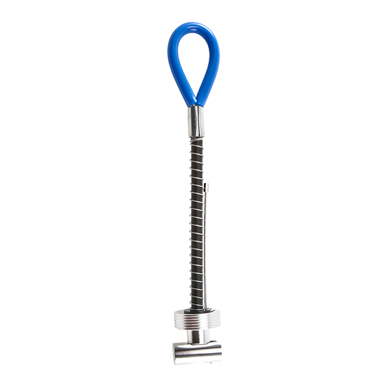
Toggle Bolt Anchor
5,000 -lbf / 22 kN
Model: A410000, A410000XK,
A410000XG, A410000XGY,
A410000XO, A410000XR,
A410000XY
Assembled in the USA
Operation and Instruction Manual
ANSI Z359.18 Type A & Z359.7-2019 / OSHA 29 CFR
1926.502 & 1910.140 / CE 2777 / EN 795:2012 Type B
WARNING:
ALL USERS OF THIS EQUIPMENT MUST READ AND
UNDERSTAND ALL INSTRUCTIONS. FAILURE TO DO SO MAY
RESULT IN SERIOUS INJURY OR DEATH. USERS SHOULD BE
FAMILIAR WITH PERTINENT REGULATIONS GOVERNING THIS
EQUIPMENT. ALL USERS OF THIS PRODUCT MUST BE PROPERLY
INSTRUCTED ON HOW TO USE THE DEVICE. AVOID CONTACT
WITH PHYSICAL HAZARDS (THERMAL, CHEMICAL, ELECTRICAL,
ETC.). MAKE ONLY COMPATIBLE CONNECTIONS.
Patent #US 8,353,653
Read This Instruction Manual Carefully Before Using This Equipment.
User Instructions must always be available to the user and are not to be removed except by the user of this equipment. For proper use, see
supervisor, User Instructions, or contact the manufacturer. Werner Co. can supply additional information upon request.
Compliant fall protection and emergency rescue systems help prevent serious injury during fall arrest. Users and purchasers of this equipment must read and
understand the User Instructions provided for correct use and care of this product. All users of this equipment must understand the instructions, operation,
limitations and consequences of improper use of this equipment and be properly trained prior to use per OSHA 29 CFR 1910.30 and 1926.503 or applicable
local standards. The local competent person must keep these instructions, make them available to users, and require their use.
Misuse or failure to follow warnings and instructions may result in serious personal injury or death.
PURPOSE
The A410000 family of products are anchorage connectors designed to function as an interface between the anchorage and a fall arrest, work positioning,
rope access, or rescue system for the purpose of coupling the system to the anchorage. Any references to "anchorage connector" in this manual include, and
apply to, the A410000 family of products.
USE INSTRUCTIONS
1.
A user must be of sound mind and body to properly and safely use this equipment in normal and emergency situations.
2.
Before using a personal fall arrest system, user must be trained in accordance with the requirements of OSHA 29 CFR 1910.30 and 1926.503
in the safe use of the system and its components.
3.
Use only with ANSI/OSHA compliant personal fall arrest or restraint systems. The anchorage must have the strength capable of supporting a
static load, applied in the directions permitted by the system, of at least 5,000-lbf (22kN) in the absence of certification.
4.
The user shall be equipped with a means of limiting the maximum dynamic forces exerted on the user during the arrest of a fall to a maximum
of 1800-lbf (8 kN). In the EU these forces must be limited to 1350-lbf (6 kN).
5.
Use of this product must be approved by an engineer or other qualified person to be compatible with any and all structural & operational
characteristics of the selected installation location and system to be connected to this anchorage connector.
6.
The anchorage connector must be inspected prior to each use for wear, damage, and other deterioration. If defective components are found
the anchorage connector must be immediately removed from service in accordance with the requirements of OSHA 29 CFR 1910.140
and 1926.502.
7.
The anchorage connector should be positioned in such a way that minimizes the potential for falls and the potential fall distance during use.
The complete fall arrest system must be planned (including all components, calculating fall clearance, and swing fall) before using.
8.
A rescue plan, and the means at hand to implement it, must be in place that provides the prompt rescue of users in the event of a fall, or
assures that users are able to rescue themselves.
9.
After a fall occurs the anchorage connector must be removed from service and destroyed immediately.
USE LIMITATIONS:
This anchorage connector has been tested in compliance with the requirements of ANSI/ASSE Z359.7. Compliance testing covers only
the hardware and does not extend to the anchorage and substrate to which the anchorage connector is attached. The anchorage connector must not be
used outside its limitations, or for any purpose other than that for which it is intended. If this anchorage connector is used differently from these instructions,
it must be designed, installed, and used under the supervision of an engineer according to ANSI Z359.6 and local building codes as applicable.
1.
The anchorage connector is designed for single user.
2.
The anchorage connector may only be loaded as shown in the LOAD DIAGRAM.
3.
The anchorage connector is designed to be used in temperatures ranging from -40°F to +130°F (-40°C to +54°C).
4.
Do not expose the anchorage connector to chemicals or harsh solutions which may have a harmful effect.
5.
Do not alter or modify this product in any way.
6.
Caution must be taken when using any component of a fall arrest, work positioning, rope access, or rescue system near moving machinery,
electrical hazards, sharp edges, or abrasive surfaces, as contact may cause equipment failure, personal injury, or death.
7.
Do not use/install equipment without proper training by a "competent person" as defined by OSHA 29 CFR 1926.32(f ).
8.
Do not remove the labeling from this product.
9.
Additional requirements and limitations may apply depending on anchorage type and fastening option utilized for installation. All placements
must be approved by an engineer or other qualified person.
10. This anchorage connector should not be used as part of a horizontal lifeline system that has not been designed and/or approved to be used
with 5,000-lbf anchorage connectors.
11. The anchorage connector should only be used for personal fall arrest and not for lifting equipment.
12. If attaching the anchorage connector to the support structure by methods other than instructed, the attachment must be certified by a
qualified person to meet the requirements of the system that will connect to the anchorage connector.
COMPATIBILITY LIMITATIONS
Anchorage connector must only be coupled to compatible connectors. OSHA 29 CFR 1926.502 and 1910.140 prohibits snaphooks from being engaged to
certain objects unless two requirements are met: it must be a locking type snaphook, and it must be "designed for" making such a connection. "Designed for"
means that the manufacturer of the snaphook specifically designed the snaphook to be used to connect to the equipment listed. The following connections
must be avoided, because they can result in rollout* when a nonlocking snaphook is used:
• Direct connection of a snaphook to horizontal lifeline.
• Two (or more) snaphooks connected to one D-ring.
• Two snaphooks connected to each other.
• A snaphook connected back on its integral lanyard.
• A snaphook connected to a webbing loop or webbing lanyard.
• Improper dimensions of the D-ring, rebar, or other connection point in relation to the snaphook dimensions that would allow the snaphook
keeper to be depressed by a turning motion of the snaphook.
*Rollout: A process by which a snaphook or carabiner unintentionally disengages from another connector or object to which it is coupled.
(ANSI Z359.0-2007)
MAINTENANCE, CLEANING AND STORAGE
Cleaning periodically will prolong the life and proper functioning of the product. The frequency of cleaning should be determined by inspection and by
severity of the environment. Clean with compressed air and/or a stiff brush using plain water or a mild soap and water solution. Do not use any corrosive
chemicals that could damage the product. Wipe all surfaces with a clean, dry cloth and hang to dry, or use compressed air. When not in use, store anchorage
connectors in a cool, dry, clean environment, out of direct sunlight and free of corrosive or other degrading elements.
V4.0-C
Advertisement
Table of Contents

Related Manuals for Werner A410000


Summary of Contents for Werner A410000
- Page 1 PURPOSE The A410000 family of products are anchorage connectors designed to function as an interface between the anchorage and a fall arrest, work positioning, rope access, or rescue system for the purpose of coupling the system to the anchorage. Any references to “anchorage connector” in this manual include, and Model: A410000, A410000XK, apply to, the A410000 family of products.
- Page 2 INSTALLATION INSTRUCTIONS: May be used as an anchor point for a leading edge Toggle Bar Anchor Loop Swage FOR HOLLOW CORE CONCRETE: restraint system. See optional anchor points below .75 inch ø (20mm) Spring for example. The use of two anchors is not required for Drill a .75 inch (20mm) hole in center of 11inches leading edge restraint systems unless otherwise...
Need help?
Do you have a question about the A410000 and is the answer not in the manual?
Questions and answers