Advertisement
- 1 Introduction
- 2 General Specifications
- 3 Usage Notes
- 4 Names and Functions of Parts
- 5 Display Block
-
6
Measurement Procedures
- 6.1 Pre-measurement inspection
- 6.2 Insulation Resistance Measurement
- 6.3 Preparing for Measurement
- 6.4 Measuring Only While the Key is Pressed
- 6.5 Measuring without Holding the Key (Continuous Measurement)
- 6.6 Discharge Function
- 6.7 AC Voltage Measurement
- 6.8 Resistance Measurement
- 6.9 Preparing for Measurement
- 6.10 Measuring Only While the Key is Pressed
- 6.11 Measuring without Holding the Key (Continuous Measurement)
- 6.12 0ΩAdjustment Function
- 7 Example of measuring the earthing conductor resistance
- 8 Comparator Function
- 9 Automatic Power-Saving Mode
- 10 Measurement principles
- 11 Documents / Resources
Introduction
Thank you for purchasing the HIOKI "3454-11 DIGITAL MΩ HiTESTER". To obtain maximum performance from the instrument, please read this manual first, and keep it handy for future reference.
Initial Inspection
When you receive the instrument, inspect it carefully to ensure that no damage occurred during shipping. In particular, check the accessories, panel switches, and connectors. If damage is evident, or if it fails to operate according to the specifications, contact your dealer or Hioki representative.
Preliminary Checks
- Before using the instrument the first time, verify that it operates normally to ensure that the no damage occurred during storage or shipping. If you find any damage, contact your dealer or Hioki representative.
- Before using the instrument, make sure that the insulation on the test leads and connection cords is undamaged and confirm that the white or red portion (insulation layer) inside the cable is not exposed. If a color inside the cable is exposed, do not use the cable. Using the product in such conditions could cause an electric shock, so contact your dealer or Hioki representative for replacements (Model L9787).
Maintenance and Service
- To clean the instrument, wipe it gently with a soft cloth moistened with water or mild detergent. Never use solvents such as benzene, alcohol, acetone, ether, ketones, thinners or gasoline, as they can deform and discolor the case.
- If the instrument seems to be malfunctioning, confirm that the batteries are not discharged, and that the test leads and fuse are not open circuited before contacting your dealer or Hioki representative.
- When an indication Err.9 appears, send the instrument for repair.
General Specifications


Usage Notes
Follow these precautions to ensure safe operation and to obtain the full benefits of the various functions.

Observe the following precautions to avoid electric shock.
- Be sure to disconnect the test lead from the object to be measured and turn the function switch OFF before connecting or disconnecting the test lead from the MΩ HiTESTER.
- Always verify the appropriate setting of the function selector before connecting the test leads. Disconnect the test leads from the measurement object before switching the function selector.

- Do not use the instrument where it may be exposed to corrosive or combustible gases. The instrument may be damaged or cause an explosion.
- Do not allow the instrument to get wet, and do not take measurements with wet hands. This may cause an electric shock.
- Do not use any other electrical source other than the batteries. The use of any other sources may result in damage of the instrument or the object to be measured and also may cause electric shock.
- Before using the instrument, make sure that the insulation on the test leads and confirm that the white or red portion (insulation layer) inside the cable is not exposed. If a color inside the cable is exposed, do not use the cable. Using the product in such conditions could cause an electric shock, so contact your dealer or Hioki representative for replacements (Model L9787).
- Do not use the instrument where it may be exposed to oil, chemicals, or solvents. Contact with these substances may cause cracking in the instrument, resulting in damage or electric shock.

- If the protective functions of the instrument are damaged, either remove it from service or mark it clearly so that others do not use it inadvertently.
- This instrument is designed for use indoors. It can be operated at temperatures between 0 and 40°C without degrading safety.
- Do not store or use the instrument where it could be exposed to direct sunlight, high temperature or humidity, or condensation. Under such conditions, the instrument may be damaged and insulation may deteriorate so that it no longer meets specifications.
- For safety reasons, when taking measurements, only use the L9787 Test Lead (or optional) provided with the instrument.
- To avoid damage to the instrument, protect it from physical shock when transporting and handling. Be especially careful to avoid physical shock from dropping.
- Calibration and repair of this instrument should be performed only under the supervision of qualified technicians knowledgeable about the dangers involved.
- Removable sleeves are attached to the metal pins at the ends of the test leads. To prevent a short circuit accident, be sure to use the test leads with the sleeves attached when performing measurements in the CAT III measurement category. Remove the sleeves from the test leads when performing measurements in the CAT I and CAT II measurement categories. For details on measurement categories, see "Measurement categories" in the instruction manual.
 NOTE
NOTE
- To avoid battery depletion, turn the function selector OFF after use (the Auto Power Save feature consumes a small amount of current).
- The safety sleeve is attached to the test lead plug. Remove the sleeve before connecting to the instrument.
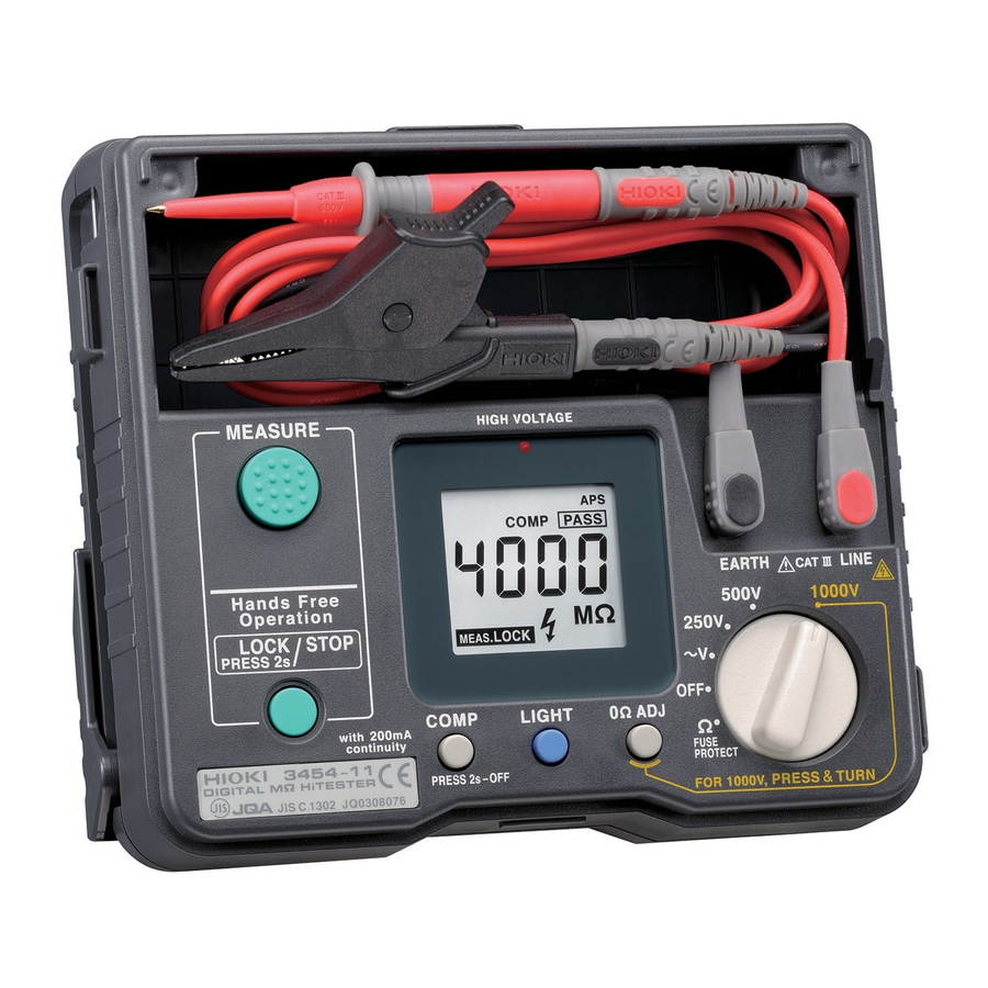
Names and Functions of Parts

- Function Selector: Selects among power ON/OFF, the output voltage for insulation resistance measurement, ACV, or resistance (Ω).
- MEASURE Key: Used to measure resistance and insulation resistance. This key remains ON while it is held down.
- LOCK Key: Used to measure resistance and insulation resistance. This key switches ON if held down for more than 2 seconds. Press the key again to turn it OFF.
- COMP Key: Used for the comparator function
- LIGHT Key: Turns the display light ON/OFF. The light automatically switches OFF after 30 seconds.
- 0ΩADJ Key: Used for the zero-adjust function in resistance measurement
Used when "1000 V" is selected in insulation-resistance measurement
Used to select the buzzer sound in the comparator function - High-voltage warning lamp: Begins flashing if the input voltage exceeds AC 70 V (±10 V) and during insulation resistance measurement.
- EARTH Measurement Terminal: Connect the black test lead to this terminal.
- LINE Measurement Terminal: Connect the red test lead to this terminal.
- Strap Hole: Pass the strap through this hole.
![]()
- Test lead Housing: Houses the test leads. The test leads may be housed without disconnecting them from the terminals after use.
- Sleeve stand: Attach the sleeve removed from the tip of the test lead.

Display Block

 : Lights up when the measured value is held during the resistance/insulation-resistance measurement.
 : Lights up when 0Ω adjustment is made during resistance measurement.
 : Indicates that battery power is low. (during which time accuracy cannot be guaranteed).
 : Lights up when auto power save is enabled.
 : Lights up when the comparator function is enabled.
 : Lights up when the measured value is less than the criterion for the comparator function during insulation-resistance measurement, or when the measured value is greater than the criterion during resistance measurement.
 : Lights up when the measured value is equal to or greater than the criterion for the comparator function during insulation-resistance measurement, or when the measured value is equal to or less than the criterion during resistance measurement.
 : Lights up when the criterion for the comparator function is indicated.
 : Lights up when "1000 V" is selected, if the 0ΩADJ key has not been pressed.
 : Lights up when the LOCK key is pressed to perform continuous measurement of insulation resistance or resistance.
 : Indicated during insulation-resistance measurement, or begins flashing when the input voltage exceeds AC 70 V (±10 V).
 : Overflow indicator. Indicated when the measurement exceeds the maximum indication value.
Measurement Procedures
Pre-measurement inspection
Ensure that the test leads are not disconnected
- Use the function selector to select Ω function.
- Short the test lead tips.
- Confirm that the reading is below 1 Ω when pressing the MEASURE key.
Insulation Resistance Measurement
To select 1000 V, set the function selector to 1000 V while pressing the 0ΩADJ.
: Overflow indication
An abbreviation for overflow, the display OF is analogous to a ∞ indication in an analog insulation tester. When measurements are larger than the effective maximum indicated values of each function, the display will indicate .
[Measurement example] When the display indicates in the 1000 V function, measurements are detected as larger than 4000 MΩ. When nothing is connected to the test lead, is also displayed.
| Display | Function | Effective maximum indicated value |
| | 250 V | 500 MΩ |
| 500 V | ||
| 1000 V | 4000 MΩ |
To avoid electric shock, always verify the appropriate setting of the function selector before connecting the test leads.
- When measuring insulation resistance, dangerous voltage is applied to the measurement terminals. To avoid electric shock, do not touch the test lead.
- Never touch the object being measured immediately after measuring. There is a danger of electric shock from the change accumulating during high voltage testing. (See Discharge Function)
- Discharge the subject conductor after measurement.
- Do not attempt to measure insulation resistance on a live conductor. Doing so could damage the instrument or cause an accident that might result in injury or death. Always turn off power to the conductor being measured before starting.
Always turn off the breaker or the measurement line.

Preparing for Measurement
- Set the function selector to 250 V, 500 V, or 1000 V. To select 1000 V, set the function selector to 1000 V while pressing the 0ΩADJ key. When the function switch is turned from OFF to 1000 V, hold down the 0ΩADJ key until "MΩ" appears on the display. If the 0ΩADJ key has not been pressed and "1000 V" is selected,
![]() appears on the display. In this case 1000 V is not applied when the MEASURE key or LOCK key is turned on.
appears on the display. In this case 1000 V is not applied when the MEASURE key or LOCK key is turned on. - Make sure that
![]() indicator does not appear. If the indicator appears, please replace the batteries.
indicator does not appear. If the indicator appears, please replace the batteries. - Connect the black test lead to the measurement terminal on the earth side ofthe instrument. Connect the red test lead to the measurement terminal on the line side of instrument.
- Connect the black test lead to the ground side of the object being measured. Except when measuring insulated resistance between ground and the object being measured, connect the black test lead to an optional point.
- Connect the red test lead to the object being measured.
Measuring Only While the Key is Pressed
- Start
- Press the MEASURE key. The high-voltage warning lamp begins flashing, and the
![]() indicator appears on the display.
indicator appears on the display. - Read the measurement after it has stabilized.
- Press the MEASURE key. The high-voltage warning lamp begins flashing, and the
- End
- Release the MEASURE key to end measurement. The current measurement is automatically held.
- When the object to be measured must be discharged, read and follow theinstructions given under "Discharge Function" below.
Measuring without Holding the Key (Continuous Measurement)
- Start
- Hold down the LOCK key for more than 2 seconds. The high-voltage warning lamp begins flashing, and the
![]() indicator and
indicator and ![]() appear on the display.
appear on the display.
The MΩ HiTESTER continues with measurement even if the LOCK key or MEASURE key is not held down. - Read the measured value after it has stabilized.
- Hold down the LOCK key for more than 2 seconds. The high-voltage warning lamp begins flashing, and the
- End (Shutdown method when
![]() is indicated)
is indicated) - Press the LOCK (STOP) key or MEASURE key to end measurement. The current measurement is automatically held.
- When the object to be measured must be discharged, read and follow theinstructions given under "Discharge Function" below.
 appear on the display.
 NOTE
- If the object to which the test leads are connected is live, even if the MΩ HiTESTER is not performing measurement, the high-voltage warning lamp and
![]() indicator will flash on the display.
indicator will flash on the display. - Insulation resistances are unstable by nature. The readings may not stabilize with some objects; this does not necessarily indicate a malfunction.
- If the object has a capacitive component, the MΩ HiTESTER may indicate a value smaller than the actual resistance immediately after the start of measurement. The reading will gradually increase to indicate the actual resistance.
- If the function switch is turned during measurement, the MΩ HiTESTER will stop measurement.
- If
![]() is indicated even if the measurement is performed with the tip of the test leads short-circuited, a conductor in the test leads may be broken.
is indicated even if the measurement is performed with the tip of the test leads short-circuited, a conductor in the test leads may be broken. - Make sure the high-voltage warning lamp off first, and then select the Resis-tance Measurement functions or OFF.
- Some objects may require time until the measurements are stable. (Approx. 5 sec.)
Discharge Function
When measuring an insulation resistance that contains a capacitance element, a charge proportional to the measurement voltage accumulates, and if undischarged could lead to an electric shock accident.
- End measurement without disconnecting the test leads from the object.
- The built-in discharge circuit automatically discharges the item.
- During discharging, the high-voltage warning lamp and
![]() indicator flash. They will go out when the voltage falls below approximately 30 V.
indicator flash. They will go out when the voltage falls below approximately 30 V. - Discharge time varies with capacity.
AC Voltage Measurement

- Test lead should only be connected to the secondary side of a breaker, so the breaker can prevent an accident if a short circuit occurs.
Connections should never be made to the primary side of a breaker, because unrestricted current flow could cause a serious accident if a short circuit occurs. - The maximum input voltage is 600 V AC. Attempting to measure voltage in excess of the maximum input could destroy the instrument and result in personal injury or death.
- To avoid electrical shock, be careful to avoid shorting live lines with the test lead.
- Set the function selector to
![]() V.
V. - Connect the test lead to the instrument's measurement terminal.
- Connect the test lead to the circuit being measured and read the displayedvalue. Do not use the MEASURE key or LOCK key.
 V.
V. Do not press the MEASURE key.
Always connect the test lead to the secondary side of the breaker.

Resistance Measurement
Never apply voltage to test lead when the Resistance Measurement functions is selected. Doing so may damage the instrument and result in personal injury. To avoid electrical accidents, remove power from the circuit before measuring.
Preparing for Measurement
- Set the function selector to Ω.
- Connect the test lead to the instrument's measurement terminal.
- Connect the test lead to the object being measured.
Measuring Only While the Key is Pressed
- Start
- Press the MEASURE key and read the displayed value.
- End
- Release the MEASURE key to end measurement. The current measurement is automatically held.
Measuring without Holding the Key (Continuous Measurement)
- Start
- Hold down the LOCK key for more than 2 seconds. The
![]() appear on the display.
appear on the display.
The MΩ HiTESTER continues with measurement even if the LOCK key or MEASURE key is not held down. - Read the measured value.
- Hold down the LOCK key for more than 2 seconds. The
- End (Shutdown method when
![]() is indicated)
is indicated)
 appear on the display.
- Press the LOCK (STOP) key or MEASURE key to end measurement. The current measurement is automatically held.
0ΩAdjustment Function
To indicate the resistance of the object itself, the zero-adjust function stores the resistances of the test leads and fuse and deducts these values from measurement values.
- Set the function selector to Ω.
- Connect the test lead to the instrument's measurement terminal.
- Short-circuit the metal tips of the test leads.
- To start measurement, press the MEASURE key, or hold down the LOCK key for more than 2 seconds.
- Press the 0ΩADJ key.
![]() lights up, and the display indicates "0.00 Ω".
lights up, and the display indicates "0.00 Ω". - Connect the test lead to the object being measured.
- Read the measured value.
 lights up, and the display indicates "0.00 Ω".
 NOTE
- The indication can be zero-adjusted when the reading is 3 Ω or less. If the 0ΩADJ key is pressed when the reading is over 3 Ω, "Err.1" is displayed.
- If the test leads are short-circuited during resistance measurement, the measurement current will exceed 200 mA, accelerating battery consumption. Perform the zero adjustment as quickly as possible and open the circuit as soon as the adjustment is complete.
- If
![]() is indicated even if the measurement is performed with the tip of the test leads short-circuited, a conductor in the test leads or the fuse may be broken.
is indicated even if the measurement is performed with the tip of the test leads short-circuited, a conductor in the test leads or the fuse may be broken.
 is indicated even if the measurement is performed with the tip of the test leads short-circuited, a conductor in the test leads or the fuse may be broken.
Example of measuring the earthing conductor resistance
If an additional operating circuit is connected in parallel to the circuit under measurement, the measurement error may occur due to the effects of impedance of the circuit connected in parallel or transient currents.
Measure the earthing conductor resistance at Ω range. Please refer to the low resistance measurement for measuring method.

Comparator Function
The comparator function compares the measurement with a set criterion, indicates PASS or FAIL, and sounds the buzzer during resistance or insulationresistance measurement.
Using Comparator
- Set the function selector to 250 V, 500 V, or 1000 V or Ω.
- Press the COMP key. The COMP indicator, REF indicator, criterion, and the condition for sounding the buzzer (
![]() or
or ![]() ) appear on the display. The display changes to the criterion-setting screen. The criterion changes each time the COMP key is pressed. Press the key repeatedly until the criterion to be used is displayed.
) appear on the display. The display changes to the criterion-setting screen. The criterion changes each time the COMP key is pressed. Press the key repeatedly until the criterion to be used is displayed.
Press the 0ΩADJ key. This switches the display between![]() and
and ![]() , allowing you to select the criterion for sounding the buzzer. For example, if you switch the display to
, allowing you to select the criterion for sounding the buzzer. For example, if you switch the display to ![]() , the buzzer sounds when the comparator result is
, the buzzer sounds when the comparator result is ![]() .
. - Press the MEASURE key or the LOCK key to start measurement. The REF indicator and the criterion go out. The display returns to the measurement display screen. The MΩ HiTESTER compares measurements and the criterion.
Result Indication
Insulation-resistance measurement: When the measurement is smaller than the criterion, is indicated. When the measurement is equal to or greater than the criterion,
 is indicated.
Resistance measurement: When the measurement is greater than the criterion, is indicated. When the measurement is equal to or smaller than the criterion, is indicated.
Select a criterion from the presets shown in the table below.
| Function | Established reference value available [MΩ] |
| 250 V/500 V | 0.2/0.4/0.5/1/2/3/5/10/20/30/50/100/200 unit [MΩ] |
| 1000 V | 1/2/3/5/10/20/30/50/100/200/500/1000/2000 unit [MΩ] |
| Ω | 0.5/1/2/3/4/5/6/10/20/50/100/200/1k unit [Ω] |
For example, when the function switch is turned to "250 V," every time the COMP key is pressed, the criterion changes as follows: 0.2 MΩ  0.4 MΩ ... 200 MΩ 0.2 MΩ ....
NOTE
- When the criterion setting screen is shown (step 2 above), if the MΩ HiTESTER remains idle for 2 seconds, the REF indicator, the criterion, and
![]() or
or ![]() are no longer displayed, and the display reverts to the previous screen. However, the COMP indicator remains on, indicating that the comparator function is enabled.
are no longer displayed, and the display reverts to the previous screen. However, the COMP indicator remains on, indicating that the comparator function is enabled. - If power is turned OFF after the comparator function is enabled, the function is automatically enabled when the power is turned ON again. The last criterion setting made before the power is turned OFF is also held.
When Not Using Comparator
To disable the comparator function, hold down the COMP key for more than 2 seconds. The COMP indicator goes out, and the comparator function is disabled.
Automatic Power-Saving Mode
The instrument will automatically enter power-saving mode about 10 minutes following the last operation, and all displayed values disappear. When the power is turned ON, the auto power save function is automatically enabled (APS lights up).
To Switch from Power-Saving Mode
Set the function selector to OFF before returning to the original position.
Disabling the Auto Power Save Function
While holding down LIGHT key, turn the function switch to turn ON the power.
Measurement principles
- Insulation Resistance Measurement
The insulation resistance of test object Rx is obtained by supplying a voltage V to the test object and measuring the current leaking from the test object and the voltage supplied using the formula (Voltage supplied, V) / (current leakage, l). - AC Voltage Measurement
This is obtained from converting the value of the current flowing from the voltage source through the instrument to a voltage value. - Low Resistance Measurement
The resistance of test object Rx is obtained by supplying a specific current l to the test object and measuring the voltage occurring between the test terminals using the formula (inter-terminal voltage, V) / (supplied current l).

Documents / ResourcesDownload manual
Here you can download full pdf version of manual, it may contain additional safety instructions, warranty information, FCC rules, etc.
Advertisement


Need help?
Do you have a question about the 3454-11 and is the answer not in the manual?
Questions and answers