
Related Manuals for Vertiv NetSure 562579


Summary of Contents for Vertiv NetSure 562579
- Page 1 NetSure™ -48 VDC Distribution Unit Installation and User Manual Specification Number: 562579...
- Page 2 The information contained in this document is subject to change without notice and may not be suitable for all applications. While every precaution has been taken to ensure the accuracy and completeness of this document, Vertiv assumes no responsibility and disclaims all liability for damages resulting from use of this information or for any errors or omissions.
-
Page 3: Table Of Contents
Vertiv™ NetSure™ -48 VDC Distribution Unit Installation and User Manual TABLE OF CONTENTS Admonishments Used in this Document ..........................iv Important Safety Instructions ..............................v Safety Admonishments Definitions ............................................v Safety and Regulatory Statements ............................................v Déclarations de Sécurité et de Réglementation ......................................v 1 Description ....................................1... -
Page 4: Admonishments Used In This Document
Vertiv™ NetSure™ -48 VDC Distribution Unit Installation and User Manual Admonishments Used in this Document will likely DANGER! Warns of a hazard the reader be exposed to that will result in death or serious injury if not avoided. (ANSI, OSHA) -
Page 5: Important Safety Instructions
Vertiv™ NetSure™ -48 VDC Distribution Unit Installation and User Manual Important Safety Instructions Safety Admonishments Definitions Definitions of the safety admonishments used in this document are listed under “Admonishments Used in this Document” on page iv. Safety and Regulatory Statements Refer to Section 4154 (provided with your customer documentation) for Safety and Regulatory Statements. - Page 6 Vertiv™ NetSure™ -48 VDC Distribution Unit Installation and User Manual This page intentionally left blank. Proprietary and Confidential © 2022 Vertiv Group Corp.
-
Page 7: Description
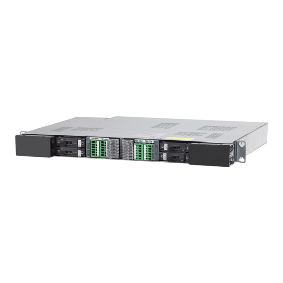
Vertiv™ NetSure™ -48 VDC Distribution Unit Installation and User Manual 1 Description A 1RU high by 19” wide distribution unit with (12) GMT fuse load positions and (4) bullet nose-type circuit breaker load positions. Provides… • (12) GMT fuse load distribution positions (0 A to 15 A). -
Page 8: Environmental
Vertiv™ NetSure™ -48 VDC Distribution Unit Installation and User Manual 2.2 Environmental Operating Ambient Temperature Range: -40 °C to +65 °C (-40 °F to +149 °F). Storage Ambient Temperature Range: -40 °C to +70 °C (-40 °F to +158 °F). -
Page 9: Accessories
Vertiv™ NetSure™ -48 VDC Distribution Unit Installation and User Manual 3 Accessories Order the following by part number as required. 3.1 23” Mounting Bracket Adapter Plates, P/N 563148 Provides two (2) mounting bracket adapters to install the shelf in a 23” relay rack or cabinet 23”... - Page 10 Vertiv™ NetSure™ -48 VDC Distribution Unit Installation and User Manual Table 3.1 Toggle Handle Bullet Nose Type Circuit Breakers Part Number Number of Ampere Number Mounting Electrical / Rating of Poles Positions Electrical Trip Mechanical Trip Required (White Handle) (Black Handle)
-
Page 11: Lugs
Vertiv™ NetSure™ -48 VDC Distribution Unit Installation and User Manual Table 3.2 GMT Fuses Ampere Rating Part Number Fuse Color 18/100 (GMT-A) 248610301 248610200 Violet 248610300 248610500 Brown 1-1/3 248610700 White 248610800 Orange 248610900 Blue 248611000 Green 7-1/2 248611300 Black-White... -
Page 12: Installing The Distribution Unit
Vertiv™ NetSure™ -48 VDC Distribution Unit Installation and User Manual Special Application Crimp Lug / Strap Combination Straps two circuit breaker wiring positions together, and provides a crimp-type lug which allows distribution wiring up to 4/0 AWG. Designed for use with 125 A and larger bullet nose-type circuit breakers, which require two mounting positions. - Page 13 Vertiv™ NetSure™ -48 VDC Distribution Unit Installation and User Manual Figure 4.1 Mounting the Distribution Unit in a Relay Rack or a Cabinet Equipment Rack Front MOUNTING HARDWARE 12-24 x 3/4" Thread Forming Hex Head Screw No. 10/12 Ground Washer Torque: 65 in-lbs.
-
Page 14: Installing Circuit Breakers And Fuses
Vertiv™ NetSure™ -48 VDC Distribution Unit Installation and User Manual 4.3 Installing Circuit Breakers and Fuses Refer to “Specifications” on page 1 for any temperature, sizing, and spacing restrictions. GMT Load Distribution Fuses Procedure Install correctly sized GMT fuses into the fuseholders located on the front of the distribution unit, as required. If a dummy fuse is installed, first remove the dummy fuse. - Page 15 Vertiv™ NetSure™ -48 VDC Distribution Unit Installation and User Manual Installing Bullet Nose Type Circuit Breakers Procedure Ensure that the circuit breaker is in the OFF position and is of the correct rating. Orient the circuit breaker as shown in Figure 4.3.
-
Page 16: Making Electrical Connections
Vertiv™ NetSure™ -48 VDC Distribution Unit Installation and User Manual 5 Making Electrical Connections 5.1 Important Safety Instructions DANGER! Adhere to the “Important Safety Instructions” presented at the front of this document. WARNING! When this panel is used in non-factory integrated systems, external branch circuit protection is required for all input feeds. -
Page 17: External Circuit Breaker / Fuse Alarm Connections
Vertiv™ NetSure™ -48 VDC Distribution Unit Installation and User Manual Procedure The frame grounding connection to the distribution unit is made by using grounding washers with the mounting hardware used to secure the distribution unit to the relay rack or cabinet. Refer to “Securing the Distribution Unit to a Relay Rack or a Cabinet Equipment Rack”... - Page 18 Vertiv™ NetSure™ -48 VDC Distribution Unit Installation and User Manual Figure 5.2 External Circuit Breaker / Fuse Alarm Connections Circuit Breaker Alarm / Fuse Alarm Circuit Card Rear (rear cover removed for clarity only) Relay shown in the deenergized state.
-
Page 19: Load Distribution Wiring To Gmt Fuse Blocks
Vertiv™ NetSure™ -48 VDC Distribution Unit Installation and User Manual 5.6 Load Distribution Wiring to GMT Fuse Blocks WARNING! Observe proper polarity when making load connections. NOTE! When used for power distribution, load should not exceed 80% of device rating, except 10 A and 15 A fuses, for which load should not exceed 70% of device rating. - Page 20 Vertiv™ NetSure™ -48 VDC Distribution Unit Installation and User Manual Table 5.2 Recommended Load Distribution Wire Size and Lug Selection for Bullet Nose-Type Circuit Breaker (Load and Load Return) (cont’d on next page) Recm 90 °C Wire Size Circuit Breaker...
- Page 21 Vertiv™ NetSure™ -48 VDC Distribution Unit Installation and User Manual Table 5.2 Recommended Load Distribution Wire Size and Lug Selection for Bullet Nose-Type Circuit Breaker (Load and Load Return) (cont’d from previous page) Recm 90 °C Wire Size Circuit Breaker...
- Page 22 Vertiv™ NetSure™ -48 VDC Distribution Unit Installation and User Manual Figure 5.3 Load Distribution Wiring and Input Wiring Front Front Load Distribution Load Distribution Circuit Breakers Circuit Breakers -48 VDC Load, Load Return: 1/4-20 studs on 5/8” centers for installation of customer provided two-hole lugs.
-
Page 23: Input Wiring
Vertiv™ NetSure™ -48 VDC Distribution Unit Installation and User Manual 5.8 Input Wiring WARNING! Observe proper polarity when making input connections. Input source and input return leads terminated in two-hole lugs are connected to threaded studs located on the rear inside of the distribution unit (refer to Figure 5.3). -
Page 24: Replacement Procedures
Vertiv™ NetSure™ -48 VDC Distribution Unit Installation and User Manual 7.2 Replacement Procedures DANGER! Adhere to the “Important Safety Instructions” presented at the front of this document. 7.2.1 Replacing a Distribution Device Replace distribution devices with the same type and rating. - Page 25 Vertiv™ NetSure™ -48 VDC Distribution Unit Installation and User Manual Connect with Vertiv on Social Media https://www.facebook.com/vertivI https://www.instagram.com/vertiv/ https://www.linkedin.com/company/vertiv/ https://www.twitter.com/vertiv/ Proprietary and Confidential © 2022 Vertiv Group Corp.
- Page 26 Vertiv.com | Vertiv Headquarters, 1050 Dearborn Drive, Columbus, OH, 43085, USA © 2022 Vertiv Group Corp. All rights reserved. Vertiv™ and the Vertiv logo are trademarks or registered trademarks of Vertiv Group Corp. All other names and logos referred to are trade names, trademarks or registered trademarks of their respective owners. While every precaution has been taken to ensure accuracy and completeness here, Vertiv Group Corp.
Need help?
Do you have a question about the NetSure 562579 and is the answer not in the manual?
Questions and answers