Table of Contents
Advertisement
Quick Links
NetSure™
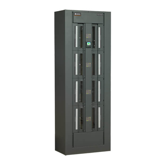
8100 SERIES -48 VDC Power Distribution System
Installation and User Manual (UM582140600), Revision A
Specification Number: 582140600
Model Number: 8100
DB
List 01
List 03
List 07
List 09
6-Panel Bay
6-Panel Bay
8-Panel Bay
8-Panel Bay
30" W x 16" D x 84" H
30" W x 24" D x 84" H
30" W x 16" D x 84" H
30" W x 24" D x 84" H
Advertisement
Table of Contents

Related Manuals for Vertiv NetSure 8100 Series


Summary of Contents for Vertiv NetSure 8100 Series
- Page 1 NetSure™ 8100 SERIES -48 VDC Power Distribution System Installation and User Manual (UM582140600), Revision A Specification Number: 582140600 Model Number: 8100 List 01 List 03 List 07 List 09 6-Panel Bay 6-Panel Bay 8-Panel Bay 8-Panel Bay 30” W x 16” D x 84” H 30”...
- Page 2 The products covered by this instruction manual are manufactured and/or sold by Vertiv Co. This document is the property of Vertiv Co. and contains confidential and proprietary information owned by Vertiv Co. Any copying, use or disclosure of it without the written permission of Vertiv Co.
-
Page 3: Table Of Contents
IB4 Board Ethernet Port ............................38 Installing and Wiring to an Optional Transient Voltage Surge Suppressor (TVSS) Device ........................39 Input/Output Cable Routing and Cable Management ........... 41 Vertiv | NetSure 8100 Series Installation & User Manual (UM582140600) | Rev. A... - Page 4 Circuit Card Replacement Procedures ....................82 Replacing a Distribution Panel........................94 Replacing an Output Bar with Sensor in a List 15A or List 25A Distribution Panel ..............................96 Vertiv | NetSure 8100 Series Installation & User Manual (UM582140600) | Rev. A...
-
Page 5: Admonishments Used In This Document
SAFETY! Informs the reader of general safety information, reminders, precautions, or policies not related to a particular source of hazard or to fire safety. (ISO, ANSI, OSHA) Vertiv | NetSure 8100 Series Installation & User Manual (UM582140600) | Rev. A... -
Page 6: Important Safety Instructions
Even a momentary short circuit can cause sparking, explosion, and injury. DANGER! Follow local lockout/tagout procedures to ensure DC branch circuit protection devices remain de-energized during installation at loads, as required. Vertiv | NetSure 8100 Series Installation & User Manual (UM582140600) | Rev. A... -
Page 7: Personal Protective Equipment (Ppe)
NOTE! When performing any step in procedures that requires removal of existing hardware, retain all hardware for use in subsequent steps, unless otherwise directed. Vertiv | NetSure 8100 Series Installation & User Manual (UM582140600) | Rev. A... -
Page 8: Static Warning
If necessary to repair equipment containing static sensitive components, wear an appropriately grounded wrist strap, work on a conductive surface, use a grounded soldering iron, and use grounded test equipment. Vertiv | NetSure 8100 Series Installation & User Manual (UM582140600) | Rev. A... -
Page 9: Customer Documentation Package
The monitor unit supports software upgrade via its USB port. A machine-to-machine HTTP interface is also available. Refer to the monitor unit instructions (UM1M832DNA) for more information. Vertiv | NetSure 8100 Series Installation & User Manual (UM582140600) | Rev. A... -
Page 10: Installation Acceptance Checklist
Factory Jumper Settings on SM-DUE Board Verified Factory Switch Settings on SM-DUH2 Board Verified Making Electrical Connections Bay Frame Grounding Connection Made External Alarm, Reference, Monitoring, and Control Connections Made Vertiv | NetSure 8100 Series Installation & User Manual (UM582140600) | Rev. A... -
Page 11: Physically Installing The System
Drill mounting holes in the floor per site requirements. Refer to Figure 1 and Figure 2 for floor mounting holes drilling dimensions. Place the bay in position. Vertiv | NetSure 8100 Series Installation & User Manual (UM582140600) | Rev. A... - Page 12 Secure the bay to the floor by installing mounting hardware into floor per site requirements. Figure 1: List 01 and List 07 Floor Hole Drilling Pattern Dimensions Figure 2: List 03 and List 09 Floor Hole Drilling Pattern Dimensions Vertiv | NetSure 8100 Series Installation & User Manual (UM582140600) | Rev. A...
-
Page 13: Installing Distribution Panel Paralleling Bars (If Furnished)
List 25A similar) Rear Distribution Panel Hardware Build-Up Paralleling Bar 3/8-16 x 1-1/4 Bolt P/N 563497 3/8 Belleville Lock Washer 3/8 Flat Washer Torque to 180 in-lbs. Vertiv | NetSure 8100 Series Installation & User Manual (UM582140600) | Rev. A... -
Page 14: Installing The Internal Ground/Return Busbar Paralleling Bars List
If internal ground/return busbars (List 17) are furnished and the paralleling bars (List 39) are furnished, attach the paralleling bars per Figure 4. Figure 4: Installing the Internal Ground/Return Busbar Paralleling Bars (List 39) (8-Panel Bay Only) Vertiv | NetSure 8100 Series Installation & User Manual (UM582140600) | Rev. A... -
Page 15: Field Installing Bay Input Feed And Shunt Assembly List 43
List 43 Input Feed and Shunt Assembly List 43 List 43 Bottom Feed Vertiv | NetSure 8100 Series Installation & User Manual (UM582140600) | Rev. A... - Page 16 Torque Values See Parts List TORQUE TO 180 IN-LBS. Apply anti-oxidation compound to busbar mating surfaces. 4 Places (2 per side) See Parts List TORQUE TO 180 IN-LBS. Vertiv | NetSure 8100 Series Installation & User Manual (UM582140600) | Rev. A...
- Page 17 List 07 List 09 List 07 List 09 Vertiv | NetSure 8100 Series Installation & User Manual (UM582140600) | Rev. A...
- Page 18 List 07 List 09 List 07 List 09 Vertiv | NetSure 8100 Series Installation & User Manual (UM582140600) | Rev. A...
- Page 19 List 01 List 03 List 01 List 03 Vertiv | NetSure 8100 Series Installation & User Manual (UM582140600) | Rev. A...
- Page 20 List 01 List 03 List 01 List 03 Vertiv | NetSure 8100 Series Installation & User Manual (UM582140600) | Rev. A...
-
Page 21: Making Switch And Jumper Settings
Circuit Cards with Jumpers and/or Switches Locations List 15A Distribution Panel (List 25A Similiar) SM-DUH2 Components removed in illustration for clarity only. SM-DUE Front (panels removed for clarity only) Vertiv | NetSure 8100 Series Installation & User Manual (UM582140600) | Rev. A... -
Page 22: Switch Settings On Ib2 Interface Board
Switch SW1 is located in ON OFF this corner of the IB2 board. Input Relay No. (+) Input Relay – No. ( Digital Input Terminal Blocks Relay Output Terminal Blocks Vertiv | NetSure 8100 Series Installation & User Manual (UM582140600) | Rev. A... -
Page 23: Switch Settings On Sm-Due
Configured by Hardware or Software Function Descriptions (Use Switch 5 of SW1) Shunt parameter is set through software (Note 1). Shunt parameter is set through DIP switch. Vertiv | NetSure 8100 Series Installation & User Manual (UM582140600) | Rev. A... - Page 24 (Use Switch 7 and 8 of SW1) Function Descriptions 500 A (Note 1) 1000 A 1500 A 2000 A Note 1: Setting for this system. Figure 8: SM-DUE Switch Location Vertiv | NetSure 8100 Series Installation & User Manual (UM582140600) | Rev. A...
-
Page 25: Jumper Settings On Sm-Due
0 mV DC to 50 mV Measure Shunt Current DC (Note 1) Measure General-Purpose Transducer 0 mA to 20 mA Measure Temperature Sensor 1 uA/K Note 1: Setting for this system. Vertiv | NetSure 8100 Series Installation & User Manual (UM582140600) | Rev. A... - Page 26 Figure 9: SM-DUE Jumper Location Vertiv | NetSure 8100 Series Installation & User Manual (UM582140600) | Rev. A...
-
Page 27: Switch Settings On Sm-Duh2
Ensure SW1 is set per Table 4. Refer to Figure 10 for location. Table 4: SM-DUH2 Switch Settings Offset Actual Address Address Communication Baud Rate: 19200 (Note 1) Communication Baud Rate: 9600 Note 1: Setting for this system. Vertiv | NetSure 8100 Series Installation & User Manual (UM582140600) | Rev. A... - Page 28 Figure 10: SM-DUH2 Switch Location Switch location Green LED may vary. Red LED Vertiv | NetSure 8100 Series Installation & User Manual (UM582140600) | Rev. A...
-
Page 29: Making Electrical Connections
T & B: 256-30695- 1880 514873 15514 Burndy: YA31L-4TCG1 The lugs should be crimped to the specifications given in the manufacturer’s instructions furnished with the crimp tool or lug. Vertiv | NetSure 8100 Series Installation & User Manual (UM582140600) | Rev. A... -
Page 30: Bay Overall Connections Diagram
Bay Overall Connections Diagram Figure 11: Bay Overall Connections Diagram Vertiv | NetSure 8100 Series Installation & User Manual (UM582140600) | Rev. A... -
Page 31: Bay Frame Grounding Connection
84 in-lbs when a standard flat washer and lock washer are used. Refer to Figure 12 for locations. NOTE! REMOVE TAPE (IF PRESENT) FROM HOLE LOCATIONS BEFORE INSTALLING LUG. Figure 12: Bay Frame Grounding Connection Points Vertiv | NetSure 8100 Series Installation & User Manual (UM582140600) | Rev. A... -
Page 32: External Alarm, Reference, Monitoring, And Control Connections
3 A Peak @ 30 VDC. The relays may be preprogrammed for specific functions. Refer to the configuration drawing (C-drawing) supplied with your system for your system’s specific configuration. Vertiv | NetSure 8100 Series Installation & User Manual (UM582140600) | Rev. A... - Page 33 C and NO terminals, and opening the contacts between the C and NC terminals. Not all I/O points are available for customer connection (some are used for factory system connections). Vertiv | NetSure 8100 Series Installation & User Manual (UM582140600) | Rev. A...
- Page 34 The remaining seven (7) relays energize during an alarm condition, closing the contacts between the C and NO terminals, and opening the contacts between the C and NC terminals. Vertiv | NetSure 8100 Series Installation & User Manual (UM582140600) | Rev. A...
-
Page 35: Auxiliary Fuse Board Connections
Auxiliary Load Connections Fuse Circuit Name Terminal Aux Load 1A (-48V) TB3-2 Aux Load 2A (-48V) TB3-1 Aux Load 3B (-48V) TB4-2 Aux Load 4B (-48V) TB4-1 Vertiv | NetSure 8100 Series Installation & User Manual (UM582140600) | Rev. A... - Page 36 Fused Auxiliary Loads to system Aux Load 3B ground bar. Aux Load 4B ABS Power A ABS_A ABS_B used ABS Power B Fused Aux. See Note 1 Loads See Note 2 Vertiv | NetSure 8100 Series Installation & User Manual (UM582140600) | Rev. A...
-
Page 37: Ground/Return Input Connections For Auxiliary Fuse Card
Ground/Return busbar. 2. If the bay is configured for A/B operation, connect “+RTN B” to the B side system Ground/Return busbar. Rear View 3. Torque to 24 in-lbs. Vertiv | NetSure 8100 Series Installation & User Manual (UM582140600) | Rev. A... -
Page 38: System Ethernet Port Connections
Default IB4 Ethernet Port Parameters IPv4 IPv6 IP Address: 192.168.1.2 IPv6 Address: 20fa:fffd:fffc:fffb:fffa:fff9:fff8:fff7 Subnet Mask: 255.255.255.0 IPv6 Prefix: Default Gateway: 192.168.1.1 IPv6 Gateway: 20fa:1:fffe:ffff:fffe:fffd:ffff:fffe Vertiv | NetSure 8100 Series Installation & User Manual (UM582140600) | Rev. A... -
Page 39: Installing And Wiring To An Optional Transient Voltage Surge
The ground cable will be installed in a position normally used for -48V distribution. It is recommended to use a Green cable and insulate the connection with shrink tubing to avoid incidental contact. Vertiv | NetSure 8100 Series Installation & User Manual (UM582140600) | Rev. A... - Page 40 List 15 (Others Similiar) (Others Similiar) Shorter Side Longer Side Longer Side Shorter Side Install TVSS Device so Shorter Side is Towards the Device's Lead Connection Points Vertiv | NetSure 8100 Series Installation & User Manual (UM582140600) | Rev. A...
-
Page 41: Input/Output Cable Routing And Cable Management
An optional load distribution cable management kit is available. See SAG582140600. This kit provides twelve (12) cable separators plus cable ties as a method to manage wiring. This kit cannot be used with the optional cable dressing bars. See Figure 20. Vertiv | NetSure 8100 Series Installation & User Manual (UM582140600) | Rev. A... - Page 42 Load Cables Cables Cables Cables Cables Cables Top View Bottom View Top Feed Installations Top Feed Installations Load Cables Input Cables Load Cables List 01, List 07 Vertiv | NetSure 8100 Series Installation & User Manual (UM582140600) | Rev. A...
- Page 43 Figure 19: Optional Cable Dressing Bars Cable Dressing Bars List 03, List 09 Cable Dressing Bars List 01, List 07 Vertiv | NetSure 8100 Series Installation & User Manual (UM582140600) | Rev. A...
- Page 44 Figure 20: Optional Load Distribution Cable Management Kit Cable Separators List 03, List 09 Cable Separators List 01, List 07 Vertiv | NetSure 8100 Series Installation & User Manual (UM582140600) | Rev. A...
-
Page 45: Load Distribution Connections
Load distribution (return side) leads terminated in the appropriate lug are connected to the “load return side” terminations provided on the optional internal ground/return bars or to external ground/return bars. See Figure 21. Torque connections as shown in Figure 21. Vertiv | NetSure 8100 Series Installation & User Manual (UM582140600) | Rev. A... - Page 46 INSTALLED IN BULLET INSTALLED IN BULLET DEVICE MOUNTING DEVICE MOUNTING BLOCK BLOCK Portion of bay removed in illustration for clarity. Rear View 8-Panel Bay (6-Panel Bay Similar) Vertiv | NetSure 8100 Series Installation & User Manual (UM582140600) | Rev. A...
- Page 47 Rear View proper polarity for the device (wired from the rear of the bay) installed, either a Distribution Device (load lead connection) or a TVSS Device (ground connection). Vertiv | NetSure 8100 Series Installation & User Manual (UM582140600) | Rev. A...
- Page 48 P/N 547991 3-Pole Lug Adapter Kit P/N 556377 Right Angle Lug Adapter Kit P/N 556378 Rear Rear Right Angle Lug Adapter Kit 582140600 List 15 582140600 List 15 Vertiv | NetSure 8100 Series Installation & User Manual (UM582140600) | Rev. A...
- Page 49 Figure 21: Load Distribution Connections (cont’d from previous page, cont’d on next page) Vertiv | NetSure 8100 Series Installation & User Manual (UM582140600) | Rev. A...
- Page 50 Assemblies.) Top Feed Arrangement Shown For Bottom Feed Arrangement, Ground Bar Assemblies Are Installed in Bottom Most Mounting Positions Front View Front View 8-Panel Bay 6-Panel Bay Vertiv | NetSure 8100 Series Installation & User Manual (UM582140600) | Rev. A...
- Page 51 Right Left (Torque to 72 in-lbs.) Side Side (Maximum Lug Width is 0.610”.) (Maximum Wire Size is 2 AWG.) Bottom Feed Typical Lug Installation 0.625” Centers Vertiv | NetSure 8100 Series Installation & User Manual (UM582140600) | Rev. A...
- Page 52 Figure 21: Load Distribution Connections (cont’d from previous page) Vertiv | NetSure 8100 Series Installation & User Manual (UM582140600) | Rev. A...
-
Page 53: Dc Input Connections
DC input return leads terminated in the appropriate lug are connected to the optional internal ground/return bars or to external ground/return bars. See Figure 22. Torque connections as shown in Figure 22. Vertiv | NetSure 8100 Series Installation & User Manual (UM582140600) | Rev. A... - Page 54 List 43 Input Feed and Shunt Assembly List 43 Bottom Feed DC Input Connections (-48V Battery) List 43 Vertiv | NetSure 8100 Series Installation & User Manual (UM582140600) | Rev. A...
- Page 55 Optional List 48 2400 A Ground/Return Bottom Feed Input Kit provides Additional DC Input DC Input Connections Connections (Battery Return Leads) (Battery Return Leads) Vertiv | NetSure 8100 Series Installation & User Manual (UM582140600) | Rev. A...
- Page 56 (Max. wire size is 4/0 AWG) Rear View 8-Panel Bay (6-Panel Bay Similar) Portion of bay removed in illustration for clarity. Bottom Feed DC Input Connections (Battery Return Leads) Vertiv | NetSure 8100 Series Installation & User Manual (UM582140600) | Rev. A...
- Page 57 Figure 22: DC Input Connections (cont’d from previous page) Vertiv | NetSure 8100 Series Installation & User Manual (UM582140600) | Rev. A...
-
Page 58: Installing Circuit Breakers And Fuses
A spare distribution fuse and alarm fuse may be placed inside the cavity provided on the front of the pull-out fuseholder portion. Record all fuse sizes installed. Figure 23: Installing TLS/TPS Fuses Vertiv | NetSure 8100 Series Installation & User Manual (UM582140600) | Rev. A... - Page 59 Install the TPL-B fuse into the fuse case. Close the fuse case. Firmly plug the fuse and fuse case into the fuse block. Record all fuse sizes installed. Figure 24: Installing TPL Fuses Vertiv | NetSure 8100 Series Installation & User Manual (UM582140600) | Rev. A...
- Page 60 Push distribution device in firmly until fully seated in the distribution panel. Record all circuit breaker sizes installed. Vertiv | NetSure 8100 Series Installation & User Manual (UM582140600) | Rev. A...
- Page 61 (Replacement P/N 248610301) Bullet nose fuseholder assembly (P/N 117201) includes fuseholder body, fuse GMT-X carrier, alarm fuse, and safety fuse cover. Safety Fuse Cover (Replacement P/N 248898700) Vertiv | NetSure 8100 Series Installation & User Manual (UM582140600) | Rev. A...
-
Page 62: Initially Starting, Configuring, And Checking System Operation
Refer to Figure 26 for locations of the monitor unit local indicators and navigation keys. Figure 26: Monitor Unit Local Indicators and Navigation Keys M832D Status Indicator (Green) Minor Alarm Indicator (Yellow) Critical or Major Alarm Indicator (Red) Menu Navigation Keys Vertiv | NetSure 8100 Series Installation & User Manual (UM582140600) | Rev. A... - Page 63 8 Feeds Press the ENT key to enter the selected menu. If any of the green fields are red in your system, it indicates an alarm condition exists. Vertiv | NetSure 8100 Series Installation & User Manual (UM582140600) | Rev. A...
-
Page 64: Application
Table 8 shows the menu navigation for some basic settings. Refer to the separate Monitor Unit Manual (UM1M832DNA) supplied with your system for complete Local Display menus. Vertiv | NetSure 8100 Series Installation & User Manual (UM582140600) | Rev. A... - Page 65 Requirement: The major alarm indicator on the monitor unit extinguishes. The monitor unit displays “System OK”. STATUS indicator at the top of the bay illuminates green. If connected and configured, remote CBA/FA alarms retire. Vertiv | NetSure 8100 Series Installation & User Manual (UM582140600) | Rev. A...
-
Page 66: Checking System Status
Verify that all FA/CBA alarm indicators located on the BDF/CBB’s front center channel (one for each distribution panel) are off. Verify there are no external alarms. Vertiv | NetSure 8100 Series Installation & User Manual (UM582140600) | Rev. A... -
Page 67: Final Steps
If any monitor unit configuration settings were changed, refer to the Monitor Unit Instructions (UM1M832DNA) and save a copy of the configuration file. This file can be used to restore the monitor unit settings, if required, at a later date. Vertiv | NetSure 8100 Series Installation & User Manual (UM582140600) | Rev. A... -
Page 68: Operating The System
POWER STATUS: This green indicator illuminates when DC power is applied to the corresponding distribution panel. Transient Voltage Surge Suppressor Device (TVSS) A TVSS contains an indicator which illuminates when the circuit activates to suppress voltages. Vertiv | NetSure 8100 Series Installation & User Manual (UM582140600) | Rev. A... - Page 69 POWER STATUS: This green indicator illuminates when DC power is applied to the corresponding distribution panel. Front View 8-Panel Bay (6-Panel Bay Similar) Vertiv | NetSure 8100 Series Installation & User Manual (UM582140600) | Rev. A...
- Page 70 Unit is non-operational. (Green) Unit is communicating with the monitor Flashing unit. Normal State Alarm (Red) Unit has failed. Figure 29: SM-DUE Indicator Locations Green LED Red LED Vertiv | NetSure 8100 Series Installation & User Manual (UM582140600) | Rev. A...
- Page 71 A 1/3 Hz flashing indicates a communication Flashing failure. Normal State Alarm Alarm (hardware fault or bus voltage (Red) sampling fault). Figure 30: SM-DUH2 Circuit Card Indicator Locations ON (DOWN) Vertiv | NetSure 8100 Series Installation & User Manual (UM582140600) | Rev. A...
-
Page 72: Maintenance
Place the new distribution panel into position on the front side of the BDF/CBB. On the front of the BDF/CBB insert and tighten the four screws securing the new distribution panel to the bay. Vertiv | NetSure 8100 Series Installation & User Manual (UM582140600) | Rev. A... - Page 73 Install the new BDF/CBB front cover panel that was furnished with the new distribution panel. Perform the “Initially Starting, Configuring, and Checking System Operation” procedure on page 62. Vertiv | NetSure 8100 Series Installation & User Manual (UM582140600) | Rev. A...
- Page 74 (Slide distribution panel cover at an angle so tabs fit into slots on bay. Secure other side of Rear View distribution panel cover with screws and ground washer as shown.) Vertiv | NetSure 8100 Series Installation & User Manual (UM582140600) | Rev. A...
- Page 75 (Slide distribution panel cover at an angle so tabs fit into slots on bay. Secure other side of distribution panel cover with screws and ground washer as shown.) Vertiv | NetSure 8100 Series Installation & User Manual (UM582140600) | Rev. A...
- Page 76 Figure 33: Connecting the System Wire Harness to the Distribution Panel To Busbar To FA Tab To Busbar To Shunt, See Figure 5 SM-DUH2 To SM-DUH2 Power Vertiv | NetSure 8100 Series Installation & User Manual (UM582140600) | Rev. A...
-
Page 77: Troubleshooting And Repair
DANGER! Adhere to the “Important Safety Instructions” presented at the front of this document. Replacing the Monitor Unit Refer to the Monitor Unit Instructions (UM1M832DNA) for a replacement procedure. Vertiv | NetSure 8100 Series Installation & User Manual (UM582140600) | Rev. A... -
Page 78: Replacing A Distribution Device
After fuse replacement is complete, re-install the access panel. Ensure grounding washers are replaced in locations noted above. Vertiv | NetSure 8100 Series Installation & User Manual (UM582140600) | Rev. A... - Page 79 (top cover panel removed for clarity only) Fuse Function Aux Load 1A Aux Load 2A Aux Load 3B Aux Load 4B ABS Power A Auxiliary Fuse Board ABS Power B Vertiv | NetSure 8100 Series Installation & User Manual (UM582140600) | Rev. A...
- Page 80 Refer to the Installing Bullet Nose Type Circuit Breakers in a List 15, List 15A, List 25, and 25A Distribution Panel” on page 60. Replacing List 10 and List 20 Distribution Panel Fuseholders For fuseholder replacement, refer to Figure 36. Vertiv | NetSure 8100 Series Installation & User Manual (UM582140600) | Rev. A...
- Page 81 1/4" Pan Head SEMS Screw (Torque to 72.0 in-lbs) Apply Anti-Oxidation Compound to Fuseholder and Busbar Contact Points List 10 Distribution Panel (List 20 Distribution Panel Similar) Rear View Vertiv | NetSure 8100 Series Installation & User Manual (UM582140600) | Rev. A...
-
Page 82: Circuit Card Replacement Procedures
Circuit Card Locations Auxiliary Fuse Board List 15A Distribution Panel (List 25A Similiar) SM-DUH2 SM-DUE Components removed in illustration for clarity only. Front (panels removed for clarity only) Vertiv | NetSure 8100 Series Installation & User Manual (UM582140600) | Rev. A... - Page 83 Remove the grounding wrist strap. Enable the external alarms, or notify appropriate personnel that this procedure is finished. Ensure that there are no local or remote alarms active on the system. Vertiv | NetSure 8100 Series Installation & User Manual (UM582140600) | Rev. A...
- Page 84 Screw and grounding washer 4-places. Remove top cover panel. Remove auxiliary fuse board. Front Customer Connections (torque 6.0 in-lbs) Factory Factory Connections Connections (disconnect/reconnect (disconnect/reconnect locking plug) two wires) Vertiv | NetSure 8100 Series Installation & User Manual (UM582140600) | Rev. A...
- Page 85 Reconnect the external wiring to the correct terminals on the customer connection terminal block. First remove the electrical tape that was applied to the bare wire end in a previous step. DO NOT allow the Vertiv | NetSure 8100 Series Installation & User Manual (UM582140600) | Rev. A...
- Page 86 Remove the grounding wrist strap. Enable the external alarms, or notify appropriate personnel that this procedure is finished. Ensure that there are no local or remote alarms active on the system. Vertiv | NetSure 8100 Series Installation & User Manual (UM582140600) | Rev. A...
- Page 87 Wire Size Capacity: 16 AWG to 26 AWG. hardware between folds Wire Strip Length: 0.20 inch. in shield. Recommended Torque: 2.2 in-lbs. Note: Refer to MAKING SWITCH AND JUMPER SETTINGS section for switch settings. Vertiv | NetSure 8100 Series Installation & User Manual (UM582140600) | Rev. A...
- Page 88 Advance Settings Menu / SW Maintenance Tab / Reboot button. Enable the external alarms, or notify appropriate personnel that this procedure is finished. Ensure that there are no local or remote alarms active on the system. Vertiv | NetSure 8100 Series Installation & User Manual (UM582140600) | Rev. A...
- Page 89 4-places. Remove top cover panel. Remove IB4 board. Front IB4 Board USB-B Port (Factory cable connected here.) 10M Ethernet Port (RJ-45) LAN Connection USB-A Port (not used) Vertiv | NetSure 8100 Series Installation & User Manual (UM582140600) | Rev. A...
- Page 90 Temporarily remove then re-insert the monitor unit. Wait for the monitor unit to initialize. Enable the external alarms, or notify appropriate personnel that this procedure is finished. Ensure that there are no local or remote alarms active on the system. Vertiv | NetSure 8100 Series Installation & User Manual (UM582140600) | Rev. A...
- Page 91 SM-DUE Relay Output Remove center panel. Remove SM-DUE circuit card. Note: Refer to MAKING SWITCH AND JUMPER SETTINGS section for switch and jumper settings. Power CAN RS-485 Vertiv | NetSure 8100 Series Installation & User Manual (UM582140600) | Rev. A...
- Page 92 Remove the grounding wrist strap. Enable the external alarms, or notify appropriate personnel that this procedure is finished. Ensure that there are no local or remote alarms active on the system. Vertiv | NetSure 8100 Series Installation & User Manual (UM582140600) | Rev. A...
- Page 93 List 15 Distribution Panel (List 15A, 25, 25A Similar) Green LED Red LED Note: Refer to MAKING SWITCH AND JUMPER SETTINGS section for switch settings. RS-485 Hall Connector 5V Power Vertiv | NetSure 8100 Series Installation & User Manual (UM582140600) | Rev. A...
-
Page 94: Replacing A Distribution Panel
Reconnect the load distribution and battery wiring to the distribution panel. Transfer the circuit breakers or fuses from the old distribution panel to the replacement distribution panel. Replace the distribution panel cover. Vertiv | NetSure 8100 Series Installation & User Manual (UM582140600) | Rev. A... - Page 95 Start the system. Refer to “Initially Starting, Configuring, and Checking System Operation” on page 62. Enable the external alarms, or notify appropriate personnel that this procedure is finished. Ensure that there are no local or remote alarms active on the system. Vertiv | NetSure 8100 Series Installation & User Manual (UM582140600) | Rev. A...
-
Page 96: Replacing An Output Bar With Sensor In A List 15A Or List 25A Distribution Panel
Replace the front panel cover over the distribution panel. Enable the external alarms, or notify appropriate personnel that this procedure is finished. Ensure that there are no local or remote alarms active on the system. Vertiv | NetSure 8100 Series Installation & User Manual (UM582140600) | Rev. A... - Page 97 Replacing Output Bar / Sensor Assembly in a List 15A or List 25A Distribution Panel Flexible SM-DUH2 Ribbon Circuit Card Cable Protective Cover Front List 15A, List 25A Similar Front Panel Cover Shoulder Bolts Output Bar with Sensor Rear Vertiv | NetSure 8100 Series Installation & User Manual (UM582140600) | Rev. A...
- Page 98 UM582140600 (RA 02/17)
Need help?
Do you have a question about the NetSure 8100 Series and is the answer not in the manual?
Questions and answers