Advertisement
Quick Links
About this Practice:
This practice has been reissued to:
• Minor formating changes. No
change to content.
Reissued Practices: Updated and
new content can be identified by a
banner in the right margin.
Issue date: November 1999
Copyright 1999 by Dantel, Inc. • Dantel is a registered trademark of Dantel, Inc. • ISO 9001 Registered
B23-41071 A
D
ISPLAY
Table of Contents
Ordering Information ........................................................................... 2
General Description .............................................................................. 2
Circuit Description ............................................................................... 3
Application Information ....................................................................... 5
Installation .......................................................................................... 10
Operation ............................................................................................ 13
Technical Specifications ..................................................................... 13
Warranty ............................................................................................. 14
CAUTION
•
Install or remove modules from the shelf only when the power is off.
If you install a module in the shelf with the power on, the internal
circuitry may suffer damage and the product warranty will be void.
•
Remove and install circuit boards only in a static-safe environment
(use antistatic wrist straps, smocks, footwear, etc.).
•
Keep circuit boards in their antistatic bags when they are not in use.
•
Do not ship or store circuit boards near strong electrostatic, electromag-
netic, magnetic, or radioactive fields.
•
For more complete information on electrostatic discharge safety
precautions, refer to Bellcore
Printed in the U.S.A.
I
& O
NSTALLATION
41071-1199 <90-00037>
LARM
U
NIT
Technical Reference # TR-NWT-000870.
TM
M
PERATION
ANUAL
Advertisement

Related Manuals for Dantel B23-41071


Summary of Contents for Dantel B23-41071
-
Page 1: Table Of Contents
For more complete information on electrostatic discharge safety precautions, refer to Bellcore Technical Reference # TR-NWT-000870. Issue date: November 1999 Copyright 1999 by Dantel, Inc. • Dantel is a registered trademark of Dantel, Inc. • ISO 9001 Registered Printed in the U.S.A. -
Page 2: Ordering Information
ORDERING INFORMATION NOTE: This section lists the different options available for this product. To order any of the avail- able options, contact Dantel Inside Sales through our toll-free number, 1-800-432-6835. OPTION NUMBER FEATURES B23-41071-00 Alarm Display Unit A25-00020-00 Replacement Lamp #48PSB... -
Page 3: Circuit Description
CIRCUIT DESCRIPTION he schematic diagram for the 41071 Alarm Display Unit is shown in Fig. 1. ♦ Ground alarm inputs are connected to the three relay coils, K1, K2, and K3 through the two banks of isolation diodes. ♦ When a relay is energized, the corresponding lamp lights and the audible alarm sounds. - Page 4 CIRCUIT DESCRIPTION . 1 - S , 41071 A CHEMATIC LARM ISPLAY 41071-1199 <90-00037>...
-
Page 5: Application Information
ULTIPLE LARM RANSMITTERS Inputs to the Alarm Display Unit can come from the A through D alarm level relay outputs from Dantel’s 46009 and 46010 Multiple Alarm Transmitters (MATs). Refer to Fig. 2. . 2 - T , 46009 46010 M... - Page 6 UDIBLE LARM ODULE You can tie alarm outputs from the relays of Dantel’s 46017 Summary Audible Alarm Module (SAAM) to the Alarm Display Unit’s inputs. The SAAM has two groups of alarms. Each group has eight inputs but only one output. As a result, the SAAM can accept only two levels of alarms, which can come from MATs or Dantel’s 46020 Multiple Alarm Processor (MAP).
- Page 7 ONTROL OINT ODULES Dantel’s 46028 and 46029 Control Point Modules (CPMs) can “echo” alarms from MATs. If you use this application, you can connect the outputs of the CPMs to the Alarm Display Unit’s inputs for alarm indication. Refer to Fig. 5.
- Page 8 APPLICATION INFORMATION . 5 - T , 46028 46029 C YPICAL ELAY ONNECTIONS ONTROL OINT ODULES 46028 AND 46029 CONTROL POINT MODULES CONTROL OUTPUT -48 VDC -48 VDC 41071 ALARM DISPLAY UNIT -48 VDC GROUND * BUS CONNECTING EVEN-NUMBERED PINS TOGETHER APPLIES TO 46029 CPM ONLY. ** WIRE EXTERNAL CONNECTIONS TO GROUND ON 46028 ONLY 41071-1199 <90-00037>...
- Page 9 APPLICATION INFORMATION TATUS ONITOR The audible and visual alarm outputs from Dantel’s 46001 Status Monitor can be wired to the Alarm Display Unit’s inputs. Refer to Fig. 6. . 6 - T , 46001 S YPICAL ELAY ONNECTIONS TATUS ONITOR...
-
Page 10: Installation
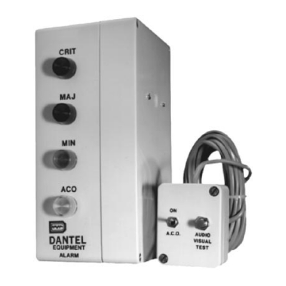
INSTALLATION o install the 41071 Alarm Display Unit, refer to Fig. 7, and follow these steps: 1. Remove the cover. Take the cover off the display box to gain access to the wire wrap pins inside. . 7 - W OCATIONS 2. - Page 11 INSTALLATION 3. Wire the ground outputs. Each relay is connected to a lamp to indicate an alarm level as follows: ♦ Refer to Fig. 7 for wire-wrap pin locations and Figs. 2-6 for examples of how the wiring can be done. ♦...
- Page 12 The unit operates at -48 VDC. Connect the power source (power off) to the display box: For -24 VDC operation, contact ♦ Dantel’s Field Service Depart- Battery to the -48V pin through a one ampere fuse and ground ment. to the +48V pin.
-
Page 13: Operation
Insert new lamp. Press lens back on. The lamps are type 48PSB and can be ordered from your local electronics store or from Dantel using part number A25-00020-00. OPERATION o make sure the lamps and audible alarm are working, push the AUDIO-VISUAL TEST button on the remote switch box. -
Page 14: Warranty
To ensure expedient processing of your order, provide a purchase order number and shipping and billing information when requesting an RMA number. Also, when the units are returned to Dantel, include a descrip- tion of the failure symptoms for each unit returned. Send defective equipment to: Dantel, Inc.
Need help?
Do you have a question about the B23-41071 and is the answer not in the manual?
Questions and answers