Advertisement
Quick Links
46009-00
46009-00
Multiple Alarm
Multiple Alarm
Transmitter
Transmitter
1
1
1
1
2
2
2
2
3
3
3
3
4
4
4
4
A1
A2
5
5
A1
A2
5
5
6
6
6
6
7
7
7
7
8
8
8
8
9
9
9
9
10
10
10
10
11
11
11
11
12
12
12
12
13
13
13
13
14
14
14
14
15
15
15
15
16
16
16
16
A
A
A
A
B
B
B
B
C
C
C
C
D
D
D
D
RST
ACK
RST
ACK
A
A
TX
TX
RX
RX
About this Practice:
This is a new document.
Reissued Practices: Updated and
new content can be identified by a
banner in the outside margin.
Issue date: March 2000
Copyright 2000 by Dantel, Inc. • Dantel is a registered trademark of Dantel, Inc. • ISO 9001 Registered
A18-05791-XX
S
MALL
46023-14
46023-14
46028-01
46009-00
SLC/VDM
SLC/VDM
Control Point
Multiple Alarm
MAC
MAC
Module
Transmitter
1
1
1
1
2
2
2
2
1
2
3
3
3
4
4
4
A1
5
5
A2
5
6
3
4
6
6
3
4
7
7
7
8
8
8
9
9
9
6
10
10
10
5
6
11
5
11
11
12
12
12
13
13
13
14
14
14
7
8
15
15
15
7
8
16
16
16
A
A
B
B
C
C
RX
9
10
9
10
D
D
TX
11
12
11
12
RST
ACK
13
14
13
14
15
16
15
16
A
A
B
A
B
TX
C
D
C
D
RX DATA
RX
RX DATA
46023-14 REV__
46023-14 REV__
Table of Contents
Ordering Information ........................................................................... 2
General Description .............................................................................. 2
Installation and Turn-up ...................................................................... 7
System Diagnostics ............................................................................ 44
Warranty ............................................................................................. 48
CAUTION
•
Install or remove modules from the shelf only when the power is off.
If you install a module in the shelf with the power on, the internal
circuitry may suffer damage and the product warranty will be void.
•
Remove and install circuit boards only in a static-safe environment
(use antistatic wrist straps, smocks, footwear, etc.).
•
Keep circuit boards in their antistatic bags when they are not in use.
•
Do not ship or store circuit boards near strong electrostatic, electromag-
netic, magnetic, or radioactive fields.
•
For more complete information on electrostatic discharge safety
precautions, refer to Bellcore
Printed in the U.S.A.
O
FFICE
A
S
LARM
46020-00
U
46034-00
MULTI-ALARM
HUBBING
N
MODULE
PROCESSOR
I
V
E
R
S
A
RESET
L
XMT DATA
L
4 9 0 2 9 - 0 0
R S 2 3 2
Y
XMT
DATA
RCV
DATA
W
RTS
DCD
I
DTR
R
CTS
E
D
A1146020-00 REV__
46034-00 REV__
TM
Technical Reference # TR-NWT-000870.
I
& O
NSTALLATION
PERATION
05791-0300 <90-00208>
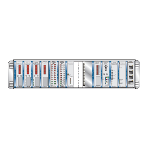
S
TANDARD
HELF
48001-01
46062-24
44124-00
46033-XX
FUSE MODULE
GENERAL
E-SYS
DATA STATION
PURPOSE
ADAPTER
TERMINATION
PROCESSOR
RX 1
1
RX 2
RX 3
CARRIER TEST
RX 4
PWR
RX 5
LOW BAT.
RX 6
RX 7
RX 8
TX 1
NORMAL
TX 2
TX 3
4
TX 4
MON
A
TX 5
T
TX 6
OUT
O
TX 7
B
TX 8
XMT
RCV
RXD
IN/2W
TXD
MON
7
B
T
B12-49013-00
O
IN
A
XMT
OUT
DATA
XMT
MASTER
RCV
CD
10
DATA
T
E
LB
S
PRINTER
T
XMT
LVL
RESET
SC
TONE
MODEM
A1146033-00 REV__
A11-46062-24 REV__
A11-48001-01 REV.
B11-44124-00 REV__
M
ANUAL
2
3
5
6
8
9
11
12
Advertisement

Related Manuals for Dantel A18-05791 Series


Summary of Contents for Dantel A18-05791 Series
-
Page 1: Table Of Contents
For more complete information on electrostatic discharge safety Issue date: March 2000 precautions, refer to Bellcore Technical Reference # TR-NWT-000870. Copyright 2000 by Dantel, Inc. • Dantel is a registered trademark of Dantel, Inc. • ISO 9001 Registered Printed in the U.S.A. -
Page 2: Ordering Information
ORDERING INFORMATION he 05791 Small Office Standard Alarm Shelf (05791) is available in a variety of options and is ordered by “List Number”. Refer to the General Description section of this manual for a discription of these options. To order the various pieces that make up the 05791 system, refer to the DJ05791 Block Diagram. - Page 3 GENERAL DESCRIPTION List 42A Adds to the List 42 an additional eight serial ports. ♦ A second MAC is added to slot 6. List 43A Adds to the List 41 or 42 thirty-two ground or loop-type discrete alarms and sixteen Form-A contact closures. ♦...
- Page 4 List 45A, 45B, or 45C cannot be used in the same shelf as a List 46A. ODULES This shelf, like many Dantel shelves is made up of separate plug-in modules that are factory-wired together to accomplish a task. The 05791 can be equipped with a variety of modules. The modules used in the 05791 shelf are described below.
- Page 5 GENERAL DESCRIPTION Fuse Module - slot 14 The B11-48001-01 Fuse Module provides 13 GMT indicating- type fuse circuits and a failure alarm circuit for fusing 400-type modules in an equipment shelf. The module fits into any 400-type or similar equipment housing and operates on -21 to -56 VDC input power.
- Page 6 This module is an interface converter and digital hub. ♦ The Hubbing Module has eight ports, strappable for RS-232 or RS-422. ♦ A ninth port on each Hubbing Module can be equipped with any standard Dantel communications subassembly to pro- vide 202 Tone, RS-422, or RS-232. 05791-0300 <90-00208>...
-
Page 7: Installation And Turn-Up
INSTALLATION AND TURN-UP his set of instructions is written specifically for the initial turn-up of the Dantel 460 Alarm Shelf 05791. Many of the settings and options contained in this instruction are applicable to other wire list configurations. However, due to the specific detail, these instructions should not be used for other than the 05791. - Page 8 INSTALLATION AND TURN-UP Components The following components will be used in this configuration: ♦ 48001-01 Fuse Module ♦ 44124 Data Station Termination (DST) (Other Network Channel Terminating Equipment (NCTE) may be substi- tuted for this module.) ♦ 46033 E-System Adapter (E-Sys) equipped with 49013 Tone Modem Subassembly ♦...
- Page 9 INSTALLATION AND TURN-UP . 1 - R 05791 S IEW OF HELF Panel ‘G’ Panel ‘F’ Panel ‘E’ Panel ‘D’ Panel ‘C’ Panel ‘B’ Panel ‘A’ 15 30 15 30 15 30 G N D With a Phillips screwdriver, mount the shelf in an equipment rack using the screws and lockwashers supplied in a bag attached to the side of the shelf.
- Page 10 ESD stud. IRING Wire the 05791 Small Office Standard Alarm Shelf to external equipment as required. Use the A18-05791-XX Block and Level Drawing or DJ05791 Block Diagram as references for making connections to Dantel equipment. ONDING AND ROUNDING ONDUCTOR AND ONNECTION...
- Page 11 INSTALLATION AND TURN-UP 2 - S TRAP AND WITCH ETTINGS Read the following items before proceeding. ♦ Observe all company guidelines regarding ESD precautions when handing modules. ♦ Always remove power from any module before removing it from the shelf. This can be accomplished by either removing the Fuse Module, or by removing the GMT-type fuse on the front of the Fuse Module for the specific slot of concern.
- Page 12 INSTALLATION AND TURN-UP . 3 - S , B11-48001 F TRAP OCATION ODULE 48001-01 Fuse Module Alarm B11-48001-01 REV.__ A - JP1 S ABLE TRAP PTIONS POSITION DESCRIPTION Pins 1 & 2 * Redundant or Single Input Pins 2 & 3 Two Independant Inputs * Setting for this application.
- Page 13 INSTALLATION AND TURN-UP 2 - MAP RS-232 S 41 & 42) UBASSEMBLY ISTS MAP -40 Set the option switches on the 46020 MAP in slot 7 per Fig. 4 and Tables B, C, and D. NOTE: Switch S5-2 is set in the ON position at this time but will be changed to the OFF position near the end of this procedure.
- Page 14 INSTALLATION AND TURN-UP C - 46020 MAP S ABLE WITCHES THRU SWITCH POSITION If shelf equipped with 46033 E-System Adapter in slot 11 If shelf is not equipped with 46033 E-System Adapter in slot 11 NOTE: A “1” indicates that the switch is up (up = OFF). A “0” indicates that the switch is down (down = ON).
- Page 15 INSTALLATION AND TURN-UP 49029 RS-232 Subassembly (on MAP) Set the straps per to Fig 5 and Table E. . 5 - 49029 S WITCH AND TRAP OCATIONS 1 2 3 E - 49029 S ABLE WITCH AND TRAP ETTINGS THRU STRAP/SWITCH POSITION -00 Mode...
- Page 16 INSTALLATION AND TURN-UP F - 46023 SMAC S ABLE WITCH PTIONS SWITCH S1 S1-1 S1-2 S1-3 S1-4 S1-5 S1-6 S1-7 S1-8 CARD ADDRESS 1 (Ports 1-8) * 2 (Ports 9-16) ** MASTER PORT DATA RATE 9600 Baud MASTER PORT PROTOCOL DCPF SWITCH S2 S2-1...
- Page 17 INSTALLATION AND TURN-UP G - 46009 MAT S ABLE WITCH AND TRAP PTIONS SWITCH POSITION Slot 1 * Slot 2 ** Slot 3 *** SW301 A/B Strap Set for position “A”. NOTE: A “1” indicates that the switch is up (up = OFF). A “0” indicates that the switch is down (down = ON).
- Page 18 INSTALLATION AND TURN-UP H - 46028 CPM S ABLE WITCH ETTINGS SWITCH POSITION Leave in “NORM” Leave in “A” position. Strap NOTE: A “1” indicates that the switch is up (up = OFF). A “0” indicates that the switch is down (down = ON). 49008 RS-422 Subassembly (on CPM) Set the straps per Fig.
- Page 19 INSTALLATION AND TURN-UP 6 - 44124 DST (L 44A) Set the option switches on the DST in slot 12 per Fig. 10 and Tables J thru N. Specific levels and equalization settings are normally determined by either the Special Services or OCS Installer at the time of the ETEL circuit installation.
- Page 20 INSTALLATION AND TURN-UP ) - 44124 DST S ABLE CONTINUED WITCH PTIONS - - - 05791-0300 <90-00208>...
- Page 21 INSTALLATION AND TURN-UP K - LF S (SL) S ABLE LOPE ETTINGS FOR OADED AND ONLOADED ABLES LOSS AT 1004 HZ WITH 404 HZ FOR REFERENCE LOW FREQUENCY SLOPE (LFSL) Loaded Nonloaded Reference Cable Cable Total S8-2(1) S8-3(2) S8-4(4) S8-5(8) (dB values) (dB values) 0.00...
- Page 22 INSTALLATION AND TURN-UP L - H (HT) S 3204 H ABLE EIGHT ETTINGS FOR LOSS AT 3204 HZ WITH 1004 HZ FOR REFERENCE HT SETTING SWITCH Calculated Reference Loss Total S7-1(1) S7-2(2) S7-3(4) S7-4(8) (dB values) 0.00 0.35 1.05 1.75 2.45 3.15 3.85...
- Page 23 INSTALLATION AND TURN-UP M - B (BW) S 2504 H ABLE ANDWIDTH ETTINGS FOR LOSS AT 2504 HZ WITH 1004 HZ FOR REFERENCE BW SETTING SWITCH Reference Total S7-5(1) S7-6(2) S7-7(4) S7-8(8) NOTE: If the calculated values of Bandwidth (BW) fall between settings, use the lower setting indicated by the table.
- Page 24 INSTALLATION AND TURN-UP N - B (BW) S 2504 H ABLE ANDWIDTH ETTINGS FOR LOSS AT 2504 HZ WITH 1004 HZ FOR REFERENCE ACCUMULATIVE SWITCH SETTINGS S7-5 THROUGH S7-8 INSTRUCTIONS: Go down the left hand column to find the number (1 through 15) that matches the reference total amplitude (HT) setting from Table D.
- Page 25 INSTALLATION AND TURN-UP 7 - 46033 E-S 202 S 45A) YS AND UBASSEMBLY 46033 E-Sys Set the option switches on the 46033 E-System Adapter in slot 11 per Fig. 11 and Tables O and P. NOTE: Switches S2-1 thru 8 on the 46033 E-Sys module set the Station Address.
- Page 26 INSTALLATION AND TURN-UP P - 46033 E-S ABLE DDRESS ETTINGS ADDRESS POSITION A “0” indicates that the rocker switch is down 01 * adjacent to the position number (closed = ON). A “1” indicates that the rocker switch is up ad- jacent to the position number (open = OFF).
- Page 27 INSTALLATION AND TURN-UP )- 46033 E-S ABLE CONTINUED DDRESS ETTINGS ADDRESS POSITION A “0” indicates that the rocker switch is down adjacent to the position number (closed = ON). A “1” indicates that the rocker switch is up ad- jacent to the position number (open = OFF).
- Page 28 INSTALLATION AND TURN-UP )- 46033 E-S ABLE CONTINUED DDRESS ETTINGS ADDRESS POSITION A “0” indicates that the rocker switch is down adjacent to the position number (closed = ON). A “1” indicates that the rocker switch is up ad- jacent to the position number (open = OFF).
- Page 29 INSTALLATION AND TURN-UP )- 46033 E-S ABLE CONTINUED DDRESS ETTINGS ADDRESS POSITION A “0” indicates that the rocker switch is down adjacent to the position number (closed = ON). A “1” indicates that the rocker switch is up ad- jacent to the position number (open = OFF).
- Page 30 INSTALLATION AND TURN-UP )- 46033 E-S ABLE CONTINUED DDRESS ETTINGS ADDRESS POSITION A “0” indicates that the rocker switch is down adjacent to the position number (closed = ON). A “1” indicates that the rocker switch is up ad- jacent to the position number (open = OFF).
- Page 31 INSTALLATION AND TURN-UP )- 46033 E-S ABLE CONTINUED DDRESS ETTINGS ADDRESS POSITION A “0” indicates that the rocker switch is down adjacent to the position number (closed = ON). A “1” indicates that the rocker switch is up ad- jacent to the position number (open = OFF).
- Page 32 INSTALLATION AND TURN-UP )- 46033 E-S ABLE CONTINUED DDRESS ETTINGS ADDRESS POSITION A “0” indicates that the rocker switch is down adjacent to the position number (closed = ON). A “1” indicates that the rocker switch is up ad- jacent to the position number (open = OFF).
- Page 33 INSTALLATION AND TURN-UP 8 - 46034 H 47A) UBBING ODULE Set the option switches on the 46034 Hubbing Module in slot 10 per Fig. 13 and Tables R and S. These settings configure the module for the following port utilization: ♦...
- Page 34 INSTALLATION AND TURN-UP R - 46034 H ABLE UBBING ODULE TRAP PTIONS OPTION STRAP POSITION DATA PORTS 1 THROUGH 8 Receive RS-232 1A through 8A Transmit RS-232 1B through 8B COMMUNICATIONS SUBASSEMBLY Subassembly RTS Select RTS always ON Subassembly Duplex Control Full-duplex S - 46034 H ABLE...
- Page 35 INSTALLATION AND TURN-UP 9 - 46062-22 GPP (L 46A) Set the option switches and straps on the 46062-22 TL1 GPP (if used) per Figs. 14 and 15 and Table T. . 14 - TL1 GPP S WITCH AND TRAP OCATIONS DOWN = ON LOW BATTERY SW 1...
- Page 36 INSTALLATION AND TURN-UP T - TL1 GPP S ABLE WITCH PTIONS SWITCH 1 S1-1 S1-2 S1-3 S1-4 S1-5 S1-6 S1-7 S1-8 Address 1 DOWN DOWN DOWN Address 2 DOWN DOWN Address 3 DOWN DOWN Address 4 DOWN Address 5 DOWN DOWN Address 6 DOWN...
- Page 37 INSTALLATION AND TURN-UP ) - TL1 GPP S ABLE CONTINUED WITCH PTIONS SWITCH 3 S3-1 S3-2 S3-3 S3-4 S3-5 S3-6 S3-7 S3-8 Data Port Baud 1200 DOWN DOWN 2400 DOWN 9600 DOWN 19200 Data Port Parity None DOWN DOWN DOWN Even DOWN Printer Port Protocol...
- Page 38 INSTALLATION AND TURN-UP . 15 - S , TL1 GPP TRAPPING IAGRAMS U1 U2 U1 U2 R2 R1 R2 R1 S2 S1 S2 S1 CC2 CC3 CC2 CC3 W1 W2 W1 W2 G2 G1 G2 G1 AA2 AA1 AA2 AA1 DD2 DD1 DD2 DD1 V1 V2...
- Page 39 INSTALLATION AND TURN-UP 3 - S OFTWARE ETTINGS AND OWNLOADING NSTRUCTIONS Read the following items before proceeding. ♦ This will assume that the shelf is now installed, all modules are configured with the proper switch and straps settings, and the system is powered up. ♦...
- Page 40 INSTALLATION AND TURN-UP Accept the defaulted values of 1200 baud, No Parity, 1 Stop Bit, and Word Length of 8. Step 3 From the Responder Menu, choose [Select Printer Responder]. At the prompt, select a protocol for the Printer Port. Select [DCPF] and press enter.
- Page 41 INSTALLATION AND TURN-UP The cursor will now be positioned to enter the Display number (MAP display) for the DCM address just entered. Since the MAT in slot 1 will be the first half of Display 32, enter “32” and press enter. Accept the defaulted Map Alarm Levels and MAT Point Levels.
- Page 42 INSTALLATION AND TURN-UP Enter the CPM address of “1” and press enter. Select [CPM] and press enter. Add your entry to the configuration by entering either “Y” or “YES”. The cursor is now positioned to enter the MAP Dsp address. Enter “1”...
- Page 43 INSTALLATION AND TURN-UP Step 7 From the MAP Menu, select [Extended Provisioning]. From the Extended Provisioning menu, select [Download MAP Options]. Accept the default values of Level D Alarm Status Only as “n”, E2 Hybrid refresh rate as “0”, TABS refresh rate of “0”, DCP refresh rate of “0”, MAP or RTU as “MAP”, and MAT or SG as “MAT”.
-
Page 44: System Diagnostics
Slot 7 - Multiple Alarm Processor (MAP) The MAP is the “brains” of the Dantel 460 Alarm and Control System. To fully understand its potential and capabilities, refer to the 46020-40 or -41 practice. The LEDs, however, are simple. - Page 45 SYSTEM DIAGNOSTICS ♦ The green A1 ON LED indicates whether points 1 through 16 or 17 through 32 are being displayed with the red LEDs de- scribed above. When the A1 LED is on, points 1 through 16 are being displayed. When the A1 LED is off, points 17 through 32 are being displayed.
- Page 46 For repairs and emergency replacements, obtain a “Returned Material Authori- zation” (RMA) number by calling Dantel and asking for the Customer Returns Representative. Please to provide a purchase order number, and shipping and billing information when requesting an RMA number.
- Page 47 NOTES 05791-0300 <90-00208>...
-
Page 48: Warranty
To ensure expedient processing of your order, provide a purchase order number and shipping and billing information when requesting an RMA number. Also, when the units are returned to Dantel, include a descrip- tion of the failure symptoms for each unit returned. Send defective equipment to: Dantel, Inc.
Need help?
Do you have a question about the A18-05791 Series and is the answer not in the manual?
Questions and answers